Note : Les descriptions sont présentées dans la langue officielle dans laquelle elles ont été soumises.
CA 02456543 2004-02-05
WO 03/013644
PCT/EP02/08609
Assembly part for an adapter of a PEG tube
and adapter for a PEG tube comprising an assembly part of this type
The invention relates to an assembly part for an adapter for the subsequent
shortening of a
PEG tube that has already been fitted for artificial feeding. Moreover, the
invention relates to
an adapter for a PEG tube comprising an assembly part of this type.
For enteral feeding, PEG tubes are known by means of which a nutrient solution
can be
passed into the stomach or the intestine of the patient. To fit a PEG tube, a
gastroscope or an
endoscope is introduced into the patient's stomach and the stomach is expanded
by air
insufflation. Subsequently, a canula is pushed into the stomach through the
abdominal wall
and the stomach wall. According to the conventional thread pull-through
procedure, a guide
thread is introduced into the stomach through the canula, gripped with a
gripping tool or
similar device of the gastroscope or endoscope and pulled out again through
the oesophagus
and the mouth of the patient. By means of this guide thread fitted in this
way, the tube is then
passed to the stomach interior and from there through the puncture site
towards the outside.
This surgical procedure is also called percutaneous endoscopically controlled
gastrostomy
(PEG).
The known PEG tubes have, at their distal end, an internal retaining element
by means of
which the flexible tube is supported on the inner stomach wall. The flexible
tube is
dimensioned such that it extends some considerable distance beyond the
abdominal wall. At
its proximal end, the tube is equipped with a connecting part to be able to
connect the
conduction system for feeding in of nutrient solution.
In practice, the known PEG tubes have proved advantageous. However, the
flexible tube
protruding relatively far outside of the abdominal wall is considered to be a
disadvantage by
active and mobile patients.
CA 02456543 2004-02-05
2
To fit the adapter, the flexible tube is fixed with surgical forceps or
clamps, for example,
above the abdominal wall and shortened to the required length: Subsequently,
the adapter is
connected to the flexible tube protruding from the abdominal wall, the fixing
action of the
forceps being released. A clamp part is provided at the adapter for fixing the
flexible tube.
US-A-5,549,657 describes an adapter which permits shorting of the flexible
tube of a PEG
tube that has already been fitted, without the need to change the tube in the
case of a flexible
tube that is still intact. The adapter has an external retaining element which
is supported on
the abdominal wall, with a connector for connecting the conduction system to
the tube.
Fitting of adapters for PEG tubes of the type described above is rendered
difficult because the
clamp is relatively large and unwieldy so that the fitting operation is
impeded.
The invention is based on the task of creating an assembly part that is secure
to handle and
simplifies shortening of a PEG tube already fitted to the required length and
fixing of the
adapter to the tube. A further task of the invention consists of providing an
adapter with such
an assembly part.
This task is achieved according to the invention by means of the
characteristic features of
claims 1 and/or 12. Advantageous embodiments of the invention are the subject
matter of the
sub-claims.
When the term PEG tube is used in the following, this is intended to mean both
the tube as
such and the actual flexible tube.
The assembly part according to the invention is configured as a loose spacer
part for the
external retaining part of the adapter and is used to fix the PEG tube to the
abdominal wall of
the patient to prevent it from sliding back. Before the adapter is fitted, the
PEG tube is fixed
to the assembly part. In this way, the PEG tube is secured to prevent it from
sliding back.
Subsequently, the PEG tube is shortened and the external retaining part of the
adapter is fixed
to the tube. Preferably, the assembly part is pushed onto the PEG tube until
it rests on the
abdominal wall.
- CA 02456543 2004-02-05
3
The assembly part can be pushed onto the abdominal wall as such or together
with the
external retaining part of the adapter. Preferably, the assembly part forms
one unit with the
external retaining part, the assembly part being releasable from the retaining
part after the
adapter has been fitted. Handling is thus simplified.
In a preferred embodiment, the assembly part consists of two parts, namely a
retaining
housing enclosing the PEG tube, which housing is placed onto the abdominal
wall, and a
retaining clip_which is used to fixed the tube into or to the retaining
housing. Preferably, the
retaining housing is equipped with a retaining part with a central bare for
passing through the
PEG tube and a gripping part which is advantageously equipped with gripping
recesses.
The retaining part and the gripping part of the retaining housing preferably
consist of two
halves which are connected by means of a hinge, in particular a film hinge.
This has the
advantage that the assembly part can be easily removed from the tube after the
adapter has
been fixed. However, the two-part design of the adapter can also be
advantageous during
assembly because the tube does not need to be passed through the bore in the
retaining part
but can simply be inserted laterally into the retaining housing and the
retaining housing shut
by closing the two halves together.
The retaining housing can also consist of two halves not connected together
which are held
together by the retaining clip. The retaining housing can also consist of a
single part and be
equipped with an intentional fracture site for dividing it during dismantling.
The retaining clip and the retaining housing may be configured such that the
retaining clip
can be either pushed into the retaining housing or onto the retaining housing.
Preferably, a
guide facility is provided on the retaining housing.
In a particularly preferred embodiment, the retaining clip for fixing the tube
in the retaining
housing is equipped with a slit into which the PEG tube is pushed laterally.
The slit contains
a first section with a larger diameter than the tube and a second section
which has the same
diameter as the tube. When the tube is inside the first section of the slit,
the assembly part can
be displaced easily on the tube. In the second section of the slit, however,
the tube is fixed. In
this way, the tube can be fixed and/or released in the retaining housing
simply by sliding the
retaining clip.
CA 02456543 2004-02-05
4
In a further particularly preferred embodiment, two stop positions are
provided, the first
section of the slit of the retaining clip being in alignment, in the first
stop position, with the
bore of the retaining housing and the second section of the slit of the
retaining clip being in
alignment, in the second rest position, with the bore of the retaining
housing. This has the
advantage that the retaining clip can be displaced between two defined
positions in which
either the assembly part is displaceable on the PEG tube or the tube is fixed
to the assembly
part.
In the following, a practical example of the invention is described in further
detail with
reference to the drawings.
Fig. 1 shows a side view of a PEG tube with adapter and assembly part in a
part
sectional drawing.
Fig. 2 shows the open retaining housing of the assembly part of the PEG tube
of
Figure 1 as a top view.
Fig. 3 shows the retaining clip of the assembly part of the PEG tube of Figure
1 as a
top view.
Fig. 4 shows the assembly part of the PEG tube of Figure 1 as a top view, the
retaining clip being in the position in which the assembly part of the PEG
tube
is freely slidable.
Fig. S shows the assembly part of the PEG tube of Figure I as a top view, the
retaining clip being in the position fixing the tube and
Fig. 6 shows a perspective view of the assembly part.
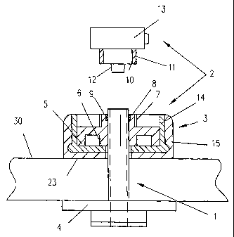
Figure 1 shows a side view of a PEG tube 1 as a part sectional illustration
together with an
adapter 2 which is equipped with an assembly part 3. At its distal end, the
PEG tube is
equipped with a plate-type internal retaining part 4 by means of which the
tube is supported
CA 02456543 2004-02-05
on the internal stomach wall. The external retaining part 5 by means of which
the tube is
supported on the abdominal wall 30 is preferably part of the adapter 2.
The external retaining part 5 of the adapter is a circular disc consisting of
a pliable
biocornpatible material with a central aperture 6 for passing through the tube
1. On its upper
side facing away from the patient, the retaining part 5 is equipped with a
lower sheath-type
clamp part 8 equipped with an external thread 7, into which an elastic clamp
ring 9 is inserted
through which the tube is passed. In an upper sheath-type clamp part 11
equipped with a
corresponding internal thread 10, a conical hollow peg 12 is arranged
concentrically onto
which the tube is pushed.
To clamp the tube 1 in a fixed position, the lower and upper clamp part 8, 11
are screwed into
each other as a result of which the elastic clamp ring 9 exerts a radial
clamping force onto the
tube.
The top section of the clamp part 11 becomes a positive Luer lock connecting
part 13 not
illustrated in further detail or a different connector to which the negative
Luer lock
connecting part of the conduction system, which is not illustrated, for
supplying nutrient
solution can be connected. In addition, adapter 2 of the tube can, for
example, be additionally
equipped with a shut-off device or a closure cap integrated into the housing
body of the
clamp parts.
In the following, the assembly part 3 of the adapter 2 of the PEG tube 1 is
described with
reference to Figures 2 to 5. The assembly part 3 consists of a retaining
housing 14 and a
retaining clip 15.
Figure 2 shows the open retaining housing 14 as a top view. The retaining
housing is
equipped with a retaining part 16 with a central bore 17 to which a gripping
part 18 with
lateral gripping recesses 19 is connected. The retaining part 16 and the
gripping part 18
consist of two halves 16', 16" and 18', 18" which are flexibly connected with
a film hinge 20
such that the retaining housing can be easily dismantled after the adapter has
been fixed to the
tube.
CA 02456543 2004-02-05
6
A central circular cut-out 21 is provided in the retaining part 16 of the
retaining housing 14,
the diameter of which is such that the external retaining part 5 of the
adapter 2 can be inserted
into the cut-out and fixed in it by clamping {Figure 1).
Figure 3 shows a retaining clip 15 as a top view. The retaining clip 5 is
equipped with an
essentially rectangular base plate 22 with rounded edges which can be laid by
its flat
underside 23 onto the abdominal wall 30 of the patient (Figure 1 ). Along the
two longitudinal
sides and one of the front sides of the base plate 22, there is an edge 24 all
around. The
dimensions of the retaining housing 14 and the retaining clip 15 are such that
the retaining
parts 16 of the retaining housing 14 can be pushed to fit into the retaining
clip 15. In this
case, longitudinal grooves 25 in the peripheral edge 24 of the retaining clip
1 S and the
longitudinal lugs 26 on the retaining part 16 of the retaining housing 14 form
a guide. Figures
4 and 5 show the parts of the assembly part 3 pushed together as a top view.
In the base plate 22 of the retaining clip 15, there is a longitudinal slit 27
whose diameter
decreases in the longitudinal direction. The slit 27 has a first section 28
with a larger diameter
that the tube 1 and a second section 29 with a smaller diameter than the tube
1.
The guide of the retaining housing 14 and retaining clip 15 has two stop
positions. The
retaining clip can be fixed in an engaged manner in the retaining housing e.g.
by lugs and
corresponding recesses. In the first stop position, the retaining clip is
pushed into the
retaining housing only so far that the first section 28 of the slit 27 in the
retaining clip 15,
which section has a larger diameter than the tube, is in alignment with the
central bore 17 in
the retaining housing 14 such that the assembly part 3 is freely displaceable
on the tube
(Figure 4). In the second stop position, the second section 29 of the slit 27
which has a
smaller diameter than the tube, is in alignment with the central bore 17 such
that the tube is
fixed in the assembly part (Figure 5).
Fitting of the adapter 2 of the PEG tube 1 can take place as follows. To fit
the adapter, the
tube 1 is first inserted into the bore 17 of the retaining housing 14 and the
retaining housing is
closed. Subsequently, the retaining clip 15 is pushed on to the retaining
housing up to the first
stop position (Figure 4). The assembly part 3 of the adapter is then pushed
forward on the
tube until the underside 23 of the retaining clip 15 rests flat on the
abdominal wall 30.
Subsequently, the retaining clip is pushed forward on the retaining housing
into the second
CA 02456543 2004-02-05
7
stop position such that the tube is secured, preventing it from sliding back
(Figure 5). The
protruding end of the tube is then cut off directly above the assembly part 3.
However, preferably, the adapter is fitted as follows. In the case of the
preferred embodiment,
the external retaining part 5 of the adapter 2 is already inserted, in a
lightly clamped position,
in the cut-out 21.of the retaining housing 14 already inserted into the
retaining clip 15, before
the assembly, the retaining clip being in the first stop position. The tube is
inserted into the
bore 17 and the assembly part pushed forward together with the retaining plate
of the adapter
onto the abdominal wall. Subsequently, the tube is fixed with the assembly
part and cut to the
required length.
The cylindrical cone 12 of the second clamp part 11 of the adapter 2 is then
introduced into
the tube 1 and the retaining housing 14 and/or the retaining clip 15 is then
pushed back into
the first stop position such that the two halves of the retaining housing are
still held together
but the tube is already freely moveable. Subsequently, the upper clamp part 11
is screwed
together with the lower clamp part 8 of the adapter 2, the lower clamp part 8
being held by
the external retaining part 5 and the upper clamp part 10 being rotated.
The retaining clip is then pulled off from the retaining housing and the
retaining housing is
removed after opening of the two housing halves. Since the assembly plate
serves as a loose
spacer part which creates a distance between the external retaining part 5 of
the adapter 2 and
the abdominal walls 30 of approximately S to 7 mm, mm, the tube 1 has
sufficient "play".
Alternatively, the external retaining part 5 of the adapter 2 can be turned
together with the
lower clamp part 8 and the upper clamp part 11 of the adapter held tight. In
this way, turning
of the tube in the stoma canal can be avoided.
The assembly part according to the invention permits simple and secure fixing
of the PEG
adapter. Errors by cutting off the tube at the wrong place leading to the
wrong tube length can
be avoided. The assembly part facilitates the secure mounting of the external
retaining part
and the lower clamp part of the adapter thus avoiding pressure being exerted
onto the
abdominal wall of the patient. If the assembly part forms a unit with the
adapter which can be
released, handling is further simplified.