Sélection de la langue

Search

Sommaire du brevet 2456880 

Énoncé de désistement de responsabilité concernant l'information provenant de tiers

Une partie des informations de ce site Web a été fournie par des sources externes. Le gouvernement du Canada n'assume aucune responsabilité concernant la précision, l'actualité ou la fiabilité des informations fournies par les sources externes. Les utilisateurs qui désirent employer cette information devraient consulter directement la source des informations. Le contenu fourni par les sources externes n'est pas assujetti aux exigences sur les langues officielles, la protection des renseignements personnels et l'accessibilité.

Disponibilité de l'Abrégé et des Revendications

L'apparition de différences dans le texte et l'image des Revendications et de l'Abrégé dépend du moment auquel le document est publié. Les textes des Revendications et de l'Abrégé sont affichés :

  • lorsque la demande peut être examinée par le public;
  • lorsque le brevet est émis (délivrance).
(12) Demande de brevet: (11) CA 2456880
(54) Titre français: SIEGE D'AUTOMOBILE AVEC VERROUILLAGE ARRIERE ET RESSORT ASSISTE
(54) Titre anglais: AUTOMOTIVE SEAT ASSEMBLY HAVING A REAR LATCH LOCK-OUT AND SPRING ASSIST
Statut: Réputée abandonnée et au-delà du délai pour le rétablissement - en attente de la réponse à l’avis de communication rejetée
Données bibliographiques
(51) Classification internationale des brevets (CIB):
  • B60N 02/20 (2006.01)
  • B60N 02/015 (2006.01)
  • B60N 02/90 (2018.01)
(72) Inventeurs :
  • FRAZIER, BRENT (Etats-Unis d'Amérique)
  • LAVOIE, SCOTT (Etats-Unis d'Amérique)
(73) Titulaires :
  • INTIER AUTOMOTIVE INC.
(71) Demandeurs :
  • INTIER AUTOMOTIVE INC. (Canada)
(74) Agent:
(74) Co-agent:
(45) Délivré:
(22) Date de dépôt: 2004-02-04
(41) Mise à la disponibilité du public: 2004-08-04
Requête d'examen: 2008-11-28
Licence disponible: S.O.
Cédé au domaine public: S.O.
(25) Langue des documents déposés: Anglais

Traité de coopération en matière de brevets (PCT): Non

(30) Données de priorité de la demande:
Numéro de la demande Pays / territoire Date
60/445,036 (Etats-Unis d'Amérique) 2003-02-04

Abrégés

Abrégé anglais


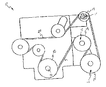
A seat assembly selectively engages forward and rearward strikers along a
floor of a motor vehicle. The seat assembly includes a seat cushion and a seat
back
pivotally coupled to the seat cushion. The seat assembly also includes a seat
riser
mounted to the seat cushion and including spaced apart rear legs. The seat
riser
includes rear latches operatively coupled to each of the rear legs for
movement
between a latched position engaged with the rear latches and an unlatched
position
disengaged from the rear latches. A spring assist member includes a lever
portion
extending between a first end fixedly secured to said rear leg and an opposite
second
distal end for engaging the rearward striker to assist in pivoting said seat
assembly
about the forward strikers as said rear latches release the rearward strikers
in the
unlatched position.

Revendications

Note : Les revendications sont présentées dans la langue officielle dans laquelle elles ont été soumises.


What is claimed:
1. A seat assembly selectively engaging forward and rearward strikers
along a floor of an automotive vehicle, said seat assembly comprising:
a seat cushion;
a seat back pivotally coupled to said seat cushion;
a seat riser coupled to said seat cushion arid including spaced apart rear
legs,
said seat riser including a rear latch operatively coupled to each of said
rear legs for
movement between a latched position engaged with the corresponding rearward
strikers and an unlatched position disengaged from the corresponding rearward
strikers; and
a spring assist member including a lever portion extending between a first end
fixedly secured to said rear leg and an opposite second distal end for
engaging the
rearward striker to assist in pivoting said seat assembly about the forward
strikers as
said rear latches release the rearward strikers in said unlatched position.
2. A seat assembly as set forth in claim 1 wherein said spring assist
member includes a coiled spring mounted along said rear leg.
3. A seat assembly as set forth in claim 2 wherein said second distal end
is a free end movable relative to said first end.
4. A seat assembly as set forth in claim 3 wherein said rear leg includes
an elongated slot for receiving said movable free end of said lever portion
therewithin.
5. A seat assembly as set forth in claim 4 wherein each of said rear legs
includes an opening for receiving and retaining the rearward strikers between
said rear
legs and said rear latches and said lever portion traversing said opening for
engaging
the rearward striker.
6. A seat assembly as set forth in claim 5 including a support post fixedly
secured to one of said rear legs for receiving said coiled spring therearound.
7. A seat assembly as set forth in claim 6 wherein said support post
includes a radial slot for receiving said first end of said lever portion.
7

8. A seat assembly as set forth in claim 7 including a release handle
operatively connected to each of said rear latches for actuating said rear
latches from
said latched position to said unlatched position thereby releasing the
rearward strikers
therefrom.
9. A seat assembly as set forth in claim 8 wherein said spring assist
member is partially coated with a plastic isolator material for dampening
vibration
between said spring assist member and the rearward strikers.
10. A seat assembly as set forth in claim 9 wherein said seat riser includes
a pair of front legs having front latches operatively coupled thereto for
selectively
engaging the forward strikers.
8

Description

Note : Les descriptions sont présentées dans la langue officielle dans laquelle elles ont été soumises.


CA 02456880 2004-02-04
AUTOMOTIVE SEAT ASSEMBLY HAVING A REAR LATCH LOCKOUT
AND SPRING ASSIST
Field of the Invention
[0001] The invention relates to a seat assembly for a motor vehicle. More
particularly, the invention relates to a spring assist member for lifting a
seat assembly
and a rear latch thereof away from a rear striker.
Description of Related Art
[0002] A seat assembly for a motor vehicle typically includes a seat cushion
adapted to be mounted to a floor, and a seat back pivotally coupled to the
seat cushion
for movement between an upright, seating position and a forwardly folded
position.
The seat cushion is frequently supported by a riser assembly, which is
detachably
coupled to the floor. More specifically, the riser assembly includes front
latches
coupled to front strikers recessed in the floor, and rear latches coupled to
rear strikers
recessed in the floor.
[0003] The front and rear latches engage the respective front and rear
strikers
to maintain the seat assembly in the aforementioned seating and folding
positions.
With the seat assembly in the folded position, the rear latch may, however, be
disengaged from the rear striker to allow the seat assembly to pivot forwardly
about
the front striker until it reaches a tumbled position. In the tumbled
position, the seat
cushion and the seat back are generally perpendicular to the floor such that
the space
vacated by the seat cushion and the seat back are now available for storage.
In order
to maximize storage space, the front latch may be disengaged from the front
striker to
allow for complete removal of the seat assembly from the motor vehicle.
[0004] Seat assemblies tend to be relatively heavy. Thus, maneuvering the
seat assembly between the various above-mentioned positions can be a
cumbersome
task. In particular, the lifting involved in moving the seat assembly from the
folded
position to the tumbled position is difficult for many individuals.
1
32sosssm
19365/096402

CA 02456880 2004-02-04
[0005) Various mechanisms for assisting movement of the seat assembly into
the tumbled position are known to those skilled in the art. For example,
United States
Patent 5,238,285 discloses a folding vehicle seat assembly including an upper
frame
for supporting a seat back, and a lower frame for supporting a seat cushion. A
pair of
support mechanisms provides for pivoting movement of the lower frame. Each
support mechanism includes first and second retention mechanisms for
releaseably
retaining the seat assembly in a use position and a tumbled position. Each
support
mechanism also includes a rear support member pivotally coupled to the lower
frame.
In addition, each support mechanism includes an upper front support member
pivotally interconnected to form a knee joint with a lower front support
member by a
pivot pin. A high-spring-rate assist spring interconnects the rear support
member and
the pivot pin. The assist spring is loaded in tension when the seat assembly
is in the
use position to assist in the movement of the lower frame from a use position
to a
tumbled position.
[0006] United States Patent 6,523,899 is directed to an automated fold and
tumble motor vehicle seat assembly: The seat assembly includes a seat cushion
and a
seat back pivotally secured thereto. A seat riser supports the seat cushion.
The seat
riser includes front and rear legs having front and rear latches releasably
engaging
respective forward and rearward strikers along a motor vehicle floor. A stop
member
is pivotally mounted to each rear leg and engages each rear latch when in a
disengaged position. A biasing member is connected to each stop member to
continuously bias the stop member into engagement with the rear latch. Clock-
type
springs are mounted on rivets along the front legs to bias the seat assembly
from an
operative position to a tumbled or storage position when the rear latches
disengage the
rear strikers. 'The clock-type springs assist in pivoting the seat assembly
toward its
tumbled position such that a rear portion of the seat assembly moves away from
the
rearward strikers when the rear legs are unlatched.
Summary of the Invention
[0007] A seat assembly selectively engages forward and rearward latches
along a floor of a motor vehicle. The seat assembly includes a seat cushion
and a seat
back pivotally secured thereto. A seat riser is coupled to the seat cushion
and includes
2
3280855v1
19365/096402

CA 02456880 2004-02-04
spaced apart rear legs. The seat riser also includes rear latches operatively
coupled to
the rear legs for movement between a latched positiom engaging the
corresponding
rearward strikers and an unlatched position disengaged from the corresponding
rearward strikers. A spring assist member includes a lever portion extending
between
a first end fixedly secured to the rear leg and an opposite second distal end
for
engaging the rearward striker to assist in pivoting the seat assembly about
the forward
strikers and into a tumbled position when the rear latches release the
rearward strikers.
Brief Description of the Drawings
[0008] Advantages of the present invention will be readily appreciated as the
same becomes better understood by reference to the following detailed
description
when considered in connection with the accompanying drawings wherein:
[0009] Figure 1 is a side view of a seat assembly according to the invention
engaging forward and rearward strikers along a motor vehicle floor;
[0010] Figure 2 is a perspective view of a seat riser including a spring
assist
member and a rear latch in a latched position;
[0011] Figure 3 is an enlarged inboard view of the rear latch in a latched
position;
[0012] Figure 4 is an enlarged outboard view of the rear latch in the latched
position;
[0013] Figure 5 is a perspective view of the seat riser including the rear
latch
in an unlatched position;
[0014] Figure 6 is an enlarged inboard view of the rear latch in the unlatched
position;
(0015] Figure 7 is an enlarged outboard view of the rear latch in the
unlatched
position; and
[0016] Figure 8 is a side view of the seat assembly in a tumbled position:
3
3280855v1
19365/095402

CA 02456880 2004-02-04
Detailed Description of the Preferred Embodiment
[0017) Refernng to Figure l, an automotive seat assembly, generally shown at
10, includes a seat cushion 12 and a seat back 14 pivotally coupled thereto. A
seat
riser 16 is coupled to the seat cushion 12. The seat riser 16 is also
detachably coupled
S to forward 18 and rearward 20 strikers disposed within recesses 22, 24 along
a floor
26 of an automotive vehicle.
[0018] Refernng to Figure 2, the seat riser 16 includes spaced apart front
legs
28, 30 and opposing rear legs 32, 34. Each of the front legs 28, 30 includes a
front
latch 36 operatively coupled thereto. The front latches 36 selectively engage
the
respective forward strikers 18. Each of the rear legs 32, 34 includes a rear
latch 38
operatively coupled thereto. The rear latches 38 selectively engage the
respective
rearward strikers 20. Each rear leg 32, 34 includes an opening 35 for
receiving and
retaining the rearward strikers 20 between the rear legs 32, 34 and the
respective rear
latches 38.
[0019] A release handle 40 is operatively connected to the rear latches 38 to
release the rear latches 38 from a latched position, shown in Figures 1
through 4, to an
unlatched position, shown in Figures 5 through 8. When the rear latches 38 are
in the
unlatched position, the seat assembly 10 pivots about the forward strikers 18
from a
generally upright position, shown in Figure l, to a tumbled position, shown in
Figure
8.
[0020] Refernng to Figures 3 and 4, each of the rear legs 32, 34 includes an
inboard surface 42 and an opposing outboard surface 44. A support post 46 is
fixedly
secured along the outboard surface 44 of each rear leg 32, 34. Each support
post 46
includes a radial slot 48.
[0021] Each of the rear legs 32, 34 also includes an elongated slot 50, shown
in Figure 3. In a preferred embodiment, the elongated slot 50 extends
longitudinally
between an upper end 52 and an opposing lower end 54.
[0022] Refernng to Figure 4, a spring assist member, generally indicated at
56, assists in pivoting the seat assembly 10 into the tumbled position. The
spring
4
3280855v1
193651096402

CA 02456880 2004-02-04
assist member 56 includes a coiled spring 58 and a Lever portion 64 extending
between a first end 60 and an opposite second distal end 62. The coiled spring
58
wraps or coils around the support post 46. Moreover, the first end 60 is
received
within the radial slot 48 of the support post 46. In a preferred embodiment,
the
second distal end 62 is a free end received within the elongated slot 50, as
shown in
Figure 3. More specifically, the free end 62 moves between the upper 52 and
lower
54 ends of the elongated slot 50 as the rear latch 38 is latched and
unlatched,
respectively.
[0023] Referring again to Figure 4, the lever portion 64 extends laterally
along
the outboard surface 44 of each rear leg 32, 34. The lever portion 64 also
traverses
the opening 35 to engage the rearward strikers 20. The free end 62 and the
lever
portion 64 are further biased towards the floor 26.
[0024] The lever portion 64 is coated with a plastic isolator material 66;
which
dampens vibration produced from rattling, squeaking, and buzzing that would
otherwise be produced by the lever portion 64 abutting against the rearward
striker 20.
The free end 62 is also coated with the plastic isolator material 66 in order
to
eliminate noise that would otherwise by produced by the movement of the free
end 62
within the elongated slot 50.
[0025] In operation, when the seat assembly 10 is in the upright position and
the rear latches 38 are in the latched position, as shown in Figures 1 through
4, the
rearward strikers 24 engage and press upwardly towards the lever portion 64
against
the bias of the spring assist member 56. The bias of the spring assist member
56
maintains a downward force against the rearward strikers 20. When the rear
latches
38 are latched, the free end 62 is located at the upper end 52 of the
elongated slot 50
along one of the rear legs 32, 34.
[0026] To move the seat assembly 10 from the upright position to the tumbled
position, the seat back 14 is first pivoted against the seat cushion 12. The
release
handle 40 is then pulled to move the rear latches 38 into the unlatched
position. In the
unlatched position, the rear latches 38 release the respective rearward
strikers 20. The
5
3280855v1
193651096402

CA 02456880 2004-02-04
downward bias force of the spring assist member 56 initially pushes downwardly
on
the top of the rearward strikers 20, which then lifts the rear legs 32, 34
away from the
floor 26 and initiates pivotal movement of the seat assembly 10 about the
forward
strikers 18 to the tumbled position. More specifically, with the first end 60
fixedly
held into place by the support post 46, the lever portion 64 and the free end
62 spring
downwardly against the rearward strikers 20 to assist in the lifting of the
seat
assembly 10. When the rear latches 38 are unlatched; the free end 62 is
located at the
lower end 54 of the elongated slot S0. The spring assist members 56 provide
sufficient force to lift about 40 lbs. approximately 12 mm in the vertical
direction.
These parameters may, however, vary depending on the type of spring, coils,
and
biasing tension predetermined in the spring assist member 56.
[0027] When the seat assembly 10 is moved from the tumbled position back to
the upright position, the spring assist members 56 initiate contact with the
rearward
strikers 20. The spring force of the spring assist member 56 is overcome by
either the
weight of the seat assembly 10 with gravity or the operator. Thus, the free
end 62
moves towards the upper end 52 of the elongated slot 50, which allows each
rear latch
38 to reengage the respective rearward strikers 20 for locking the seat
assembly 10 in
the upright position.
[0028] The invention has been described in an illustrative manner, and it is
to
be understood that the terminology, which has been used, is intended to be in
the
nature of words of description rather than of limitation.
[0029] Many modifications and variations of the invention are possible in
light of the above teachings. It is, therefore, to be understood that within
the scope of
the appended claims, the invention may be practiced other than as specifically
described.
6
32sosss~l
19365/096402

Dessin représentatif
Une figure unique qui représente un dessin illustrant l'invention.
États administratifs

2024-08-01 : Dans le cadre de la transition vers les Brevets de nouvelle génération (BNG), la base de données sur les brevets canadiens (BDBC) contient désormais un Historique d'événement plus détaillé, qui reproduit le Journal des événements de notre nouvelle solution interne.

Veuillez noter que les événements débutant par « Inactive : » se réfèrent à des événements qui ne sont plus utilisés dans notre nouvelle solution interne.

Pour une meilleure compréhension de l'état de la demande ou brevet qui figure sur cette page, la rubrique Mise en garde , et les descriptions de Brevet , Historique d'événement , Taxes périodiques et Historique des paiements devraient être consultées.

Historique d'événement

Description Date
Exigences relatives à la révocation de la nomination d'un agent - jugée conforme 2021-04-01
Inactive : CIB désactivée 2019-01-19
Inactive : CIB du SCB 2018-01-27
Inactive : CIB expirée 2018-01-01
Exigences relatives à la révocation de la nomination d'un agent - jugée conforme 2012-01-17
Inactive : Lettre officielle 2012-01-13
Inactive : Lettre officielle 2012-01-11
Demande visant la révocation de la nomination d'un agent 2011-12-13
Le délai pour l'annulation est expiré 2011-02-04
Demande non rétablie avant l'échéance 2011-02-04
Réputée abandonnée - omission de répondre à un avis sur les taxes pour le maintien en état 2010-02-04
Modification reçue - modification volontaire 2009-10-23
Lettre envoyée 2009-01-07
Toutes les exigences pour l'examen - jugée conforme 2008-11-28
Requête d'examen reçue 2008-11-28
Exigences pour une requête d'examen - jugée conforme 2008-11-28
Inactive : Lettre officielle 2008-11-14
Exigences relatives à la révocation de la nomination d'un agent - jugée conforme 2008-11-14
Inactive : Lettre officielle 2008-11-13
Demande visant la révocation de la nomination d'un agent 2008-10-08
Lettre envoyée 2005-01-27
Inactive : Transfert individuel 2005-01-10
Demande publiée (accessible au public) 2004-08-04
Inactive : Page couverture publiée 2004-08-03
Inactive : CIB en 1re position 2004-04-01
Inactive : CIB attribuée 2004-04-01
Inactive : Lettre de courtoisie - Preuve 2004-03-16
Demande reçue - nationale ordinaire 2004-03-10
Inactive : Certificat de dépôt - Sans RE (Anglais) 2004-03-10

Historique d'abandonnement

Date d'abandonnement Raison Date de rétablissement
2010-02-04

Taxes périodiques

Le dernier paiement a été reçu le 2008-12-12

Avis : Si le paiement en totalité n'a pas été reçu au plus tard à la date indiquée, une taxe supplémentaire peut être imposée, soit une des taxes suivantes :

  • taxe de rétablissement ;
  • taxe pour paiement en souffrance ; ou
  • taxe additionnelle pour le renversement d'une péremption réputée.

Les taxes sur les brevets sont ajustées au 1er janvier de chaque année. Les montants ci-dessus sont les montants actuels s'ils sont reçus au plus tard le 31 décembre de l'année en cours.
Veuillez vous référer à la page web des taxes sur les brevets de l'OPIC pour voir tous les montants actuels des taxes.

Historique des taxes

Type de taxes Anniversaire Échéance Date payée
Taxe pour le dépôt - générale 2004-02-04
Enregistrement d'un document 2005-01-10
TM (demande, 2e anniv.) - générale 02 2006-02-06 2005-12-20
TM (demande, 3e anniv.) - générale 03 2007-02-05 2006-12-20
TM (demande, 4e anniv.) - générale 04 2008-02-04 2007-12-21
Requête d'examen - générale 2008-11-28
TM (demande, 5e anniv.) - générale 05 2009-02-04 2008-12-12
Titulaires au dossier

Les titulaires actuels et antérieures au dossier sont affichés en ordre alphabétique.

Titulaires actuels au dossier
INTIER AUTOMOTIVE INC.
Titulaires antérieures au dossier
BRENT FRAZIER
SCOTT LAVOIE
Les propriétaires antérieurs qui ne figurent pas dans la liste des « Propriétaires au dossier » apparaîtront dans d'autres documents au dossier.
Documents

Pour visionner les fichiers sélectionnés, entrer le code reCAPTCHA :


Pour visualiser une image, cliquer sur un lien dans la colonne description du document. Pour télécharger l'image (les images), cliquer l'une ou plusieurs cases à cocher dans la première colonne et ensuite cliquer sur le bouton "Télécharger sélection en format PDF (archive Zip)" ou le bouton "Télécharger sélection (en un fichier PDF fusionné)".

Liste des documents de brevet publiés et non publiés sur la BDBC .

Si vous avez des difficultés à accéder au contenu, veuillez communiquer avec le Centre de services à la clientèle au 1-866-997-1936, ou envoyer un courriel au Centre de service à la clientèle de l'OPIC.


Description du
Document 
Date
(aaaa-mm-jj) 
Nombre de pages   Taille de l'image (Ko) 
Description 2004-02-03 6 307
Abrégé 2004-02-03 1 23
Revendications 2004-02-03 2 66
Dessins 2004-02-03 3 104
Dessin représentatif 2004-05-04 1 10
Certificat de dépôt (anglais) 2004-03-09 1 158
Courtoisie - Certificat d'enregistrement (document(s) connexe(s)) 2005-01-26 1 105
Rappel de taxe de maintien due 2005-10-04 1 109
Rappel - requête d'examen 2008-10-06 1 117
Accusé de réception de la requête d'examen 2009-01-06 1 177
Courtoisie - Lettre d'abandon (taxe de maintien en état) 2010-03-31 1 172
Correspondance 2004-03-09 1 26
Correspondance 2008-10-07 17 614
Correspondance 2008-11-12 1 18
Correspondance 2008-11-13 1 26
Correspondance 2012-01-10 1 18
Correspondance 2012-01-12 1 19
Correspondance 2011-12-12 19 699