Note : Les descriptions sont présentées dans la langue officielle dans laquelle elles ont été soumises.
CA 02456897 2004-02-04
C~ R P fN E TT N Pq E Tt
$ W P N T P O M ,S
~oooa.~ The present invention concerns a method for programming the sf,attenns
df project~'les according to claim i and a tube weapon wfth a prograrr~mirZg
system according to claim fi. "i'he priority of awiss Patent Application No.
2003
02S8I03 of Febrc~ary 26, 2003 is claimed.
fOQOZ] in Connection with the invention the terra tube wet~porr is to be
e~nderstood
to include sub tube weapons which are suited to the launching of projectiles,
especially grenades, whose trajectories are strongly curved and which
preferably
tie in the tower angle group. The angles of descent of the projectiles which
are
launched by such tube weapons in the context of the invention lie in a range
which is ldrger than about 5°. Such tube weapons are used in genera!
far
destruction of land and sea targets,
(~QO31 To obtain a maximum weapon effect with a shatterabia projectile, the
shattering of the projectile must take place in the nearby space surrounding
the
target to be destroyed. So that this happens, projectiles with programmable
ignition are used, which in general are referred to as programmable or fuse
sellable projectiles. The goat of the programming is to achieve with similar
projectiles, which are launched with similar elevations and which thereby fly
along basically the same trajectory, detonation at different shattering points
according is the position of the target with respect to the tube weapon.
foQ~l Customarily in the programming the projectiteS are net sa directly
programmed that they detonate at a given shattering point. More often the time
of the Smattering or the flight duration of the prpjeCtile between the weapon
sr~d
the shattering point is programmed, For this either the flight duration can be
directly programmed, or the number of projectile rotations up to detonation is
pre-set.
CA 02456897 2004-02-04
IU0051 So that the prolectil2 dzvelops an optimal effect several conditions in
regard to the shattering point must be Observed.- The shattering of the
projectile
should take place at an optimal distance in reference to the target. The basis
of
this is the following: in the shattering or detonation of Such proj~ctiteg
numerous
fragments or splinters ase formed. These splinters in general have only a
smelt
mass bt~t a high initial speed. t7f course this speed diminishes rapidly
because
of air resistance. The splinters move outwardly from the detonatir~n paint,
into a
splinter space, which for example can be referred to as a scatter cane. The
effectiveness of the splinters t~ essentially a function of th8ir mass, their
materials, and their shape as welt their apesd at the target. This effect
diminishes with diminishing Speed, or in other words, witfi increasing
distance
from the shattering point. The spatial etfiective region of such grenades or
projectiles with exptosiVe material is accordingly narrowly limEted. For
detgmtirting tt~e optimal point for shattering the grenades into splinters two
important conditions are therefore to betaken ir>ta account: first the
shattering
should take place as close as possible to the target, to develop a high
efifc~et on
the target; in the case of earth and ea targets this means that the grenades
must be detonated in the field surrounding the target. To aehieve a good
striking
likelihood for the splinters the shattering must take piac~ at a not too
srr~ati
distance from, to the target. The Hight ime up to the shattering must
absolutely
kse determined so that the shattering occurs before; the impact. The mentioned
conditions set narrow boundaries for the optimal region of the shattering
point
and especially for the height range of the Shattering point.
t0046j Cannons are generally used for the d~struction of targets with
elongated
shots_ The trajectories of the projectiles launched in thi:~ way are therefore
elongated or only Slightly elevated and exhibit therefore overall only a small
elevation above the ground relative to ttte attacked target. These pto~ectites
are
customarily so programmed that they are detonated at a certain longitudinal
CA 02456897 2004-02-04
distance from the weapon, Because of the elongated flight paths in this case
the
projectiles detonate 8t low heights above the target.
(ooo7j r;?ther tube weapons, especially tube weapons ire the style of grenade
launchers, shoot projectiles or grenades along trajectories which are more
Strongly elevated or Curved than the trajectories of the above-mentioned
Cannon
projectiles. In the case of these projectiles the programming takes place in
the
same way as with cannon projectiles, so that the programming takes into
account the important requirement that the detonation point of a projectile
should
lie at a definite; small as possible, height above the tarciet.
LOb08~ Indeed different possibilities are known for allowing the projectiles
to
detonate ott an optimal position with the corresponding programming of the
projectile taking into account the actual muzzle velocity or the deviation of
the
a~vai muzzle velocity from a known muzzle velocityr. U.S. Patent No. 5,814,756
for example describes haw the shattering time can be :~o corrected that the
horizontal Shattering diStanCe in front of the target remains constant as much
possible. Also, tJ.S. Patent >~Jo. 5,89x,102 describes a method far correcting
the
shattering time for the purpose of maintaining a constant shattering distance
between the weapon and the shattering point. Another method #or shattering a
grenade at a given horizontal distance from the weapon is revealed by U.S.
Patent Application 20421488367, wherein however nv measurement of the
muzzle velocity and no programming of tile projectile results, but the
detonation
is triggered by a radaw signal. All three mentiorEed documents therefore
describe
methods by which detonation of a projectile takes place; at a predetermined
f~orizanta( distance.
~o0D9) Obviously the disadvantage of using the customary programming method
originally designed for the elongated shooting of projectiles, which are siZOt
along
heavily curved trajectories, ties in that these projectiles because Of their
elevated
CA 02456897 2004-02-04
4
trajectories are not detonated over the target at the optimal height and
thereby
have no satisfactory effect.
foo~o] Moreover, in actuality the detonation of the pro~eCtiles does not occur
at
alt, or only by chance, at those exact points at which they are supposed to
take
place according to the programming, since, as already mentioned, for different
reasons always a certain Scattering occurs. An essential ground far the
scattering ties in that the actual rnuzzte velocities of the projectiles
tleviatE from
the theoretically calculated muzzle velOCity of the projectiles, with however
the
programming being made on the basis of the ttreoretica( muzzle velocity.
~a~oi~j it is now the object of the invention,
to provide a method by means of which the effeptiveness of projectiles,
the trajectories of which are not elongated, is irnprOVed even if a deviation
of the actual muzzle Velocity of the projective fron~i the thearetieal muzafe
velocity is present;
and to propose a tube weapon with a programming system which is
suited to the carryirtt~ out of the method.
Lo0L21 The solution to this object in accordance with the invention occurs
for the method, through the features of Claim y ; and
for the tube weapon with the programming system, by the features of
claim 6.
Iaoz3~ Advantageous further developments of this method and of this tube
weapon with the new programming system are defined by the associated
dependent claims.
IO~x.41 The new method is especially, but not exclusively, used for tube
weapons, hereinafter designated as weapons, which are slot in the lower angle
CA 02456897 2004-02-04
group. The projectiles are programmed by the transrrEission of programming or
a
Corresponding signal. The calGU(st(ons for the prpgramming take place with
referer<ce to the position of the targets launch and tern~(na( ballistic
criteria, a
predetermined muzzle velocity, an actual or measured muzzle velocity of at
least
one of the projectiles, and the baundary Condition that the detonation should
occur at a shattering point which lies at an optimal height above the target:
C00~,51 In a pre-caiculatian the predetermined theoretical muzzle velocity is
used.
lri a definitive calGUiation two thoughts are combined, (lamely the caking
into
account Qf the actual muzzle uelacity, which is determined by a measurement,
and the maintenance of the optimum height of the shattering point.
(oo~.s~ in this, the precalcu(ation can be carried out before the measurement
of
the actual muzzle velocity, and after the measurement of the actual muzzle
velocity a calculation Correction, and with it the ultimate calculation, can
be
carried out; or he entire u(t(mats calculation can take place after the
determination of the actual muzzle velocity.
(00171 With the new method one achieves the shattering of prosectiles, such as
grenades which are shat along strongly curved tr2tjectories, at are optimal
height
over tire target: The otherwise usual scattering, caused by the deviation of
the
actual muzzle velocity trorn the predetermined muz~ie ~relacity, is
pr~otica~ity
avoided by taping into consideration the actual or measured muzzle velocity.
Taking int4 account the actual or measured muzzle Velocity for optimizing the
height of the detonation location is new, since customarily by taking into
consideration the actual or measured muzzle velocity. the shot length, that
is,
the longitudinal distance of the detonation place from the weapon, was
optimized.
CA 02456897 2004-02-04
6
C00~81 The ne'rir method and the new programming system are, as already
mentioned several times, intended especially for tube weapon, for exempts
infantryr weapons or machine cannons, which are suited for the shooting of
projectiles along strongly curved trajectories and preferably in the tower
angle
group, wherein the descent angle relative to the horizontal exceeds about
5°.
[0919I Generatty tube weapons used within the framework of the invention are
those which are at least semi-automatic or automatic tube weapons, especially
grenade launchers or machine cannons, The programming according to the
method of the invention can however, also be carried taut for projectiles
fired as
individual shots.
(0020 For the Currying out of th~ method, a tube weapon with a programming
system is peed. That prt>gramming system has according to the invention v~.
measuring means, computing means including memory means for the
processing of data for the programming, and transmission means for the
transmission of the programming or corresponding signals to the projectiles.
[0o21~ Preferably integrated distance mea$uring means are provided far
measuring the longitudinal distance oP the target from tine tube weapon. For
this
however an external distance measuring means curl also be used, and in certain
cases the mentioned longitudinal distance can also be determined with the help
of topographical maps.
too22~ The construction of the tube weapon with the programming system is
preferably such that the delivery of projectiles 1S blocked if, as a result of
the
computations for the programming; a. shattering point results which lies
within a
safety field around the tube weapon. The safety field is essentiaify dependent
on the projectiles or their effective area.
CA 02456897 2004-02-04
E00231 Tube weapons for the deiivery of prajectit2s in serial fire and with
the ne~v
prograrrrming system are preferably so constructed that a sertai firing ar a
#iring
trurst is initiated by a shooter and is continued until an interruption is
caused by
the shooter.
I0~024] tt is advantageous it upon an interruption flf serial fire certain
settings are
maintained, e$pecialiy, in case the same target is again to be destroyed, the
settings associated with the longitudinal distance of the target. A further
serial
firing or a further firing burst for destroying the same target can then take
place
without further input, and only upon the destrUCtion of a new target mast the
associated settings be changed. The tube weapon cart however also be so
constructed that at the end of a serial firing or firing burst the used set
values are
candel(ed.
C002s] (rr the following the inventipn isdesCribed in detail by way of
examp)es
and with reference to the drawings: The drawings are not to scale. They show:
Fig. 1 the flight behavior of shatterable projectiles for explaining terms
used in the framework of the description;
Fig. 2 a tubular Wreaporr and a target to be destroyed, for explaining the
determination of suitable settings, in schematic representation;
Fig. 3 a tube weapon and a target as well as flight paths of similar
projectiles with similar programming, wherein only computation for
preprogramming teices place but not for Correction of the final
programming in a representation similar t~o dig. 2;
Fig_ 4 a tube weapon and a target as wait as fiigHt paths of similar
projeGtiies, wherein ct~rnputation steps for precalculafiGn and for
definitive CBtcuiation take place, in a representation similar to that
of Figs. 2 and 3:
Fig. ~ a tube weapon with a prvgrarl~ming system according to the
invention, in schematic representation.
CA 02456897 2004-02-04
(nnz6) First of at! different terms, isnown its thems81v8S, 'which appear in
the
following text or In Flgs. .t-4, will be explained.
(0027( Input specific magnitudes are: a destruction distance or a longitudinal
distance xt of a target Z, a longitudinal distance xa of a shattering point
C~, and
an optirr~al longitudinal distance xa' of an optimal shattering point Q' from
a tube
weapon 12; and further tz, that i5, the fused duration time, which begins to
can
wtth the ignition of the proj~iaite G and at the end of which the shattering
of the
projectile G takes place at the shattering point Q. The working coordinates
are
designated by x and y.
~OOZ81 Further influential magnitudes, for each of the known types of
projectiles
O, are: first, the effective distance w of a gr~;nade G; which is a function
of the
grenade type and which over the destruction distance x or a region of the
longitudinal distance is practicality constant; second, the error distance u!
third,
the height y or the elevation in the y-direction of the detonation point Q for
a
given target Z: and fourth. the fault allowance system h"
t00z9~ Stiff other influential values are a known or rtOrmat muzzle velocity
va(Oj of
the projectile G arid an actual muztte velocity va (aft) of the projectile G,
i"Or a
preralcutation the predetermined or predeterrntned or normal rnu2zte velocity
vo
(Oj is used, and it is established that the shattering is to take place at a
time t,
whioti can be calculated from the different influential values. T;he effective
muzzle velocity Va(eff) differs in genera! from tf~e predetermined muzzle
velocity
vo(0) and therefore must ire measured. For the ultimate calculation the
effective
muzzle velocity V o(eff) is taken into cansideratton. it a calcuiati~on is
made with
only the predetermined muzzle veioC~ty vo(p~, the shattering Of the projectile
G is
based on an imparted signal after a flight duration t. if the ultimate
calculation is
made with the actual muzzle velocity va(eff~, the signal imparted to the
projectile
CA 02456897 2004-02-04
G, and which determines the flight time to the shattering, must be so Changed
so
that the shattering or detonation takes place after the flight duration t +
et. dt fs
a time error and can be either a positive or negative value. 4t should be as
srnafl as possible.
[0434] The elevation ?~ of the weapon tube '13 of the tube weapon 12 is sea
before the firing of the projectile G; and it allows the solution of knr~wn
fundamental ballistic equations, from vvtlich the flight duration is
determined.
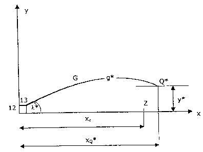
~Q031~ Fig. t shows the tube weapon 12 with a weapon ube 13 and a target Z to
be destroyed at a longitudinal distance xZ from the ube weapon 12. The
projectile G, trvith which the target Z is to be destroyed, moves iri
dependence on
the input elevation ~, ofi the weapon tube 'i3 over different projectile
trajectories g
or g'. The suiiabie elevation ~.' iS that which the prajecaile G reaCh~es on
the
Optima! projectile trajectory g*, so that the proje~Ctile G upon its
shatt4ring at the
longitudinal distance x~" from the tube weapon 12 is at an optimal height y'
above the target Z. An optimal programming has the result that the projectile
G
at this optirr~al height y" detonates at an optima! shatteripg point Q'.
Vlrlttv the
shattering of a projectile G resulting fragments move away in all directions
from
the shattering point witn r2tative fragment veiOCities. T'he absolute velocity
flf
each fragment is composed of the fragment velocity and of the projectile
velocity. The target Z is optimally located approximately in the middle of a
surface in which the plane of the target Z and the splinter space, where the
splinters of the projectile G detonated at Q' disburse, intersect one another.
I0032j Fig. 2 illustrates the behavior of theoretically ballisticaity
similarly acting
projectiles ~ which are snot at the same elevation n. arud with the same
programming. The calculations for the programming in this case take into
account only the predetermined muzzle velocity vo(0); a correction for taking
into
account the actual muzzle velocity vo(eff) is not made. For clarity onEy three
CA 02456897 2004-02-04
i0
projectiles t~ are represented, but in actuality a series can caniatn far more
than
three projectiles. The. tube weappn 12, which has the weapon tube 13; shoots
the projectiles G to destroy the target Z by a preceding caic~lation, and with
the
given presumed elevation ~ of the weapon tube i 3 and taking into account a
known lethality of the projectile G, the precatcutatlon gives a flight time t
up to
the detonation. This precatculation takes place on the basis of the
predetermined muzzle velocity vo~C1), The shattering points C~ of the
projectiles G
then theoretically lie at the optimal height y"; above the target Z to be
destroyed
and at a longitudinal dlstac~ce xQ' from the tube weapon 12, whereas in the
previous case the shattering points Q !ay somewhat closes to the tube weapon
i 2 than the target Z, which is situated at the distance xz from the tube
weapon
~ a.
t0~33I if the actual muzzle velocity vo(eff) Of the projectile G coincides
with the
predetermined muzzle velocity vo(0), then according to f"!g. 3, assuming the
absence of disturbing influences, ail projectiles G move along a common
optimal
praj8ctite prajectory g' and detonate at the shattering point Q$. Generally
and as
often mentioned, the actual muzzle velocity of the projectile G deviates from
the
predetermined muzzle velocity vo(0) ofi the projectile G. This is the primary
reason why the projectii85 G, as illustrated in Fig. 3, even with Shooting at
the
same elevation, move not on, or not only on, the optirnai tfiajectory g* but
on
other trajectories g; and even witfi~ the same programming do not, or do not
only.
detonate at the Optimum shattering point Q" but also at other shattering
paints Q.
COQ34j According to the invention the actual muzzle velocity vo(eff) of at
feast one
of the projectiles G is now measured. Taking into accoctnt the actual,
measured
muzzle velocity vo(eff), or its deviation Pram tha predetermined muzzle
velocity
vo(0), an ultimate calculation, ar a computation correction, is obtained, and
on
the basis of the results of the ultimate Computation, the programmEng for the
prOjecti(es is produced. The trajectories g, over which the projectiles G
move,
CA 02456897 2004-02-04
1t
are the same as in Fig. 3, that is, the same as ii the programming were
carried
out only on the basis of the precalculation without taking into account the
aciuai
muzzle veiocity:va(eff). But the ultimate calculation for th8 programming is
such
that the Shattering points G~ of all of the projectiie8 G lie at the optimum
height y"
of the opttmur~r~ shattering point Q* above the target Z, aS is illustrated in
Fig. 4.
~~035) The advantage of the optimum height y' of stl sh~tt~ring points C~ is
above all a longitudinal deviation of the detonation point Q from x~~. If this
longitudinal deviation is so large that the targ~L Z is no !anger efficiently
destroyed by many of the prajectlles G, another eie~r~ation ~. will have to be
chosen.
[OO36~ The rr~iddle value of the measured muzzle velocities of earlier or
previously shat projectiles can be used as the predetermined muzzle velocity
vo(eff). To always obtain shattering points A'* with optimal heights y' about
the
target Z, a measurement of the efifeative muzzle velocity vo(eff) should be
carried
out for each projectile G.
[0037] For carrying out the above-described method the tube weapon 't 2 is
equipped with a programming system. existing tube weapons, for example,
infantry weapons such as grenade launchers ar machine cannons, Can, be
modified as needed to fnciude i~he new programming system, so that a
destrucfion et#eCt increase can be achieved.
Fooas) 'fhe programming system has vQ-measuring means t4, computer means
y 6 and transmission means 18, for the transmission of calculated data from
the
computing means 16 to the projectiles G, inrludittg a trartsrnission unit at
the
tube rrveapon t 2. The vo-measuring means i 4 are generally arranged in tire
area of ~e rrmzale of the weapon tube 13, before or after the muzzle section.
The transmission means t 8 are so constructed and arranged that the
CA 02456897 2004-02-04
i2
transrnisSion Of the data to the projactites G takes place between a
projectile
loading point and the end of th~ weapon tube '13 before the launching of the
projectiles.
ro039~ A~9 already mentioned, the ultimate calculation according to the new
method has the result that the prajectlles G are so programrr~ed that tf~ey
indeed
detonate at the optimal height y" above the target Z, rather than at the
optimal
longitudinal distance xo* from fihe'tube weapon. This probiert~ has presented
itself earlier in the de~tructiori of surface targets, and as a solution it
was then
proposed that the shooting bo dont~ in a so-Called chain o! pearls mode. Hy
this
the fotiowirig is to be understood: In the abstract similar projectiles are
shot.
These projectiles follow, apart from the usual inner and t errninai
ballisticatiy
occurring strays, in principle similar trajectories; which naturally then only
coincide if the azimuth and eievatiort are not changed. 'These similar
projectiles
ace now dissimilarly programmed, of the program& tranSnirtttrd to them ace
dissimilarly calculated, so that from the launching to the shattering the
first
projectile i~as the longest flight duration and each successive projectile has
a
shorter flight duration. in this case, the characteristics of the projectories
do not
change, but tt~e end points of the trajectories of the unshattered projectiles
shift
closer to the tube v~eapon with each suCCessiVety fired projectile. ~y tuning
the
flight times of the projectiles to the cadence of the tube weapon, if wantad,
a
number of projectiles can be detonated simultaneously. Especially in the case
of
night time 5~hooting this offers an obsErver a picture which at some distance
can
be compared to a chain of pearls, and from this is derived the term "chain of
pearls mode". It should also be known that shooting m the pearl ofi chain mode
does rot necess~anly rr~ean chat the projectiles detonate simultaneously.
X0040) If one combines the idea of programming projectiles G for point
shooting
mode according the in~rentson, that is; the maintenance of the optimal height
y'
of the shattering point O"', with the idea of the known chain of pearls mode,
a
CA 02456897 2004-02-04
t3
very advantageous method can result from it. This makes possible the
programming of projectiles for tube weapons by means crf which point targets,
that is, targets with known azimuth, can be efficiently destroyed with
strongly
curved trajectories and indeed even with a considerable; longitudinal
deviation of
the detonation points. In this case, above all, for a rndjo~r portion Of the
projectiles
a certain height deviation from the optimal height y' of the shattering paint
Q
must be taken as a cost involved:
~OQ4ij Naturally with the chain of pearls mode an improvement cars be achieved
even if no Consideration is given t0 the deviation of the effective and
predetermined muzzle velocity, and accordingly if na va measurement takes
place and/or if the measurement or estimation of the longitudinal distance of
the
target trom the weapon is performed inexactly.
(0092] A further problem which presents itself in connection with the Shooting
Of
programmable projectiles by tube weapons is the following: Tube weapons irt
the context of the invention are, as already rnentioned, frequently used for
the
deStruciion of Surface targets which are not accurately detectable frflm
within the
surface or are themselves movable t8rgets. To achisvE3 hits the entire surface
must be covered with shots: This can in the point shooting mode, that is, with
a
number of similarly programmed projectiles, be achieved in that in the firing
of a
series of projectiles the weapon tube is pivoted in axtmuth as well as in
elevation. The weapon tubes of infantry weapons are rnostiy directed by muscle
pourer 2nd can changed in azimuth during the firing of a series of projectiles
without anything further. A surface can thereby be covered in its breadth with
fire in the point shooting mode by swinging the weapon tube in azimuth, with
longitudinal straying being able to help cover the surface aver a certain but
limited length with fire. tn ihis way Surfaces which are ;seen in the shooting
direction not as having large dimension$ can be covered with fire in a
satisfactory way.
CA 02456897 2004-02-04
It~043] Often, however, surieces are to be covered with fire, which surtaxes
as
seen in the shooting direction have relatively large dimensions. 'With the
above-
described point hooting mode, that is, with tre firing of ~rojectites with
sirr~ilar
programming, with or without CaICUlattipn COfrGCtiOtt to take into account the
ac~ai muazle velocity, indeed without anything further, such surfaces can 5e
covered with fire in their width but not trt their enl~re length.
t00s4~~ It is therefore also here sought to use the above-described known
method
of the customary chain of peaels mode far tube weapons within the seeps of the
invention, for which weapons the term infantry tube weapons is used. Thereby,
in firing on a surface 'target whose longitudinal range from the weapon is
large,
as seen in the shooting direction, a satisfactory weapon effect cart be
achieved
by shooting in the point shooting mode. With projectiles, which in this
customary
chain of pearls mode are shot from infantry tube weapons and which therefore
hare a corresponding chain of pearls programming, the: surrounding field of a
targ4t not ~eccurateiy IOCated or a Surface target C3n be hit even if it is
assumed
that the elevation during the shooting !s not changed. It the shots during the
shooting also do not change in azimuth, then the impart surtace Consists Of-a
strip of land ty'rrtg in the shooting direction in frrrnt of the weapon. If
the shots
during the shooting change in azimuth, - and that is actuai(y intended in the
destruction of surtace targets, then the impaot surface conSiS'ts however Only
of
a strip of Land tying diagtrnatly in front of the weapon, try which ; trip tie
detonation points of the successively shot projectiles in step wise fashion
Come
nearer to the weapon:
IOa~1 This disadYantage can be removed by a rrtethod for shaoting with
infantry
tube weapons in a modified chain of pearls mode. In this case the projectiles
are so programmed that the detonation points of the individual projectiles
change in a step-wise fashion, and indeed not only in One direction, that is,
with
CA 02456897 2004-02-04
steadily shortened shattering times, but instead a tirst group of projectiles
of a
series are progr~arnmed with progressively shortening shattering times, a
second
group are programmed with progressively lengthening shattering times, and this
is continued with each group being oppOSitety progr&mnled in carnparison to
the
proceeding group. The division of projectiles into groups is ltctioriat and
serves
only as a perceived description of the new method. The projectiles of the
different groups differ from ane another, as already mentioned, not in their
construction but only in their programming.
(oos.6l Custorr~arily the projectiles are so progrdmmed that the flight
dtrrations of
the projectiles of the first groVp 6teadily diminish and the flight durattons
Of the
projectiles of the second group steadily increase. '
ioo~71 The number of projectiles ire each group can ba predetermined or can be
set from case-to-case or from use~to-use.
E004s1 A group whose projectiles detortate with tiirninlshing distance from
the
weapon is in principle ended when the predetermined or fixed number of
projectiles have beset shot. Advantageously, however; an interlock is provided
for the purpose of ending a group before the detonation point of a projectile
fails
outside a safety distance from the weapon,
(04491 The second group of projectiles generally is followed by further groups
witri the projectiles of each successive group being oppositely ptogramrned:
(00501 During the cut off of each group by the programming, or as the case may
be by the maintaining of the safety distance if necessary, it is advantageous
if
the cut oif of the entire firing burst is not the result of a given
d4tratiot~, or is not
according to a number ofi disohargec! projectiles, but instead the result of a
,~ CA 02456897 2004-02-04
determination by shooter himself to end the final burst. Irr this mann8r tf~e
shooter is not sucprised by a sudden a»ding of the burst.
foos~:~ The programrr~ing can be so constructed that a roprogr2~mming from
progressively cleser detonation points to progressively farther detvnat3on
points
is coupled with a pi~roting of the'weapon shout a given minimum angle.