Note : Les descriptions sont présentées dans la langue officielle dans laquelle elles ont été soumises.
CA 02456941 2004-02-04
COLOR AND INTENSITY MEASURING MODULE FOR TEST OF LIGHT
. EMITTING COMPONENTS BY AUTOMATED TEST EQUIPMENT
CROSS-REFERENCE TO RELATED APPLICATIONS)
This application claims priority from U.S. Provisional
Application No. 60/450,03.3 filed February 26; 2003
FIELD OF THE INVENTION
' The present invention relates to the optical testing of
light-emitting components and, more particularly, to a test
module which may be used in conjunction with conventional
automatic test equipment to optically test light-emitting
components.
BACKGROUND OF THE INVENTION
Electronic assemblies are built with a multitude of
light-emitting components, primarily light emitting diodes
(LED's), to indicate functions, or faults occurring on the
assemblies. In addition to light, information on the nature
of the operations,of faults on these assemblies is conveyed by
the color emitted by the devices. Light emitting diodes are
available in colors covering the entire visible spectrum as
well as white.
Various methods have been implemented to verify the
correct operation of these light-emitting components, from
test sequences where human verification is used, to photo
detectors employed to perform the tests automatically.
Human verification is slow and unreliable. While
photodetectors can easily verify that Light is present,
validation of the correct color has become extremely
important. Photodetectors employing narrow bandpass color
filters have been employed to test for the proper emitted
'
-1-
CA 02456941 2004-02-04
wavelength, with limited success, since variations in output
Levels of the photodetector cannot discriminate intensity from
~ colors approaching the edge of the passband. This becomes
critical in the very narrow color bands in the visible
spectrum.
In addition, these. implementations require that each
photodetector be customized for the particular wavelength of
the light-emitting component under test, adding lead time and
w expense to their use: Current photodetector solutions are
available in various configurations, some having the detector
itself mounted near the light--emitting component, where others
use fiber optic cable to collect the light and present it to a
remotely mounted photodetector. Consequently, a need exists
for a test module for automated test equipment to test light
emitting components which addresses the problems associated
with prior test apparatus.
SUMMARY OF THE INVENTION
The present invention provides a test module and a method
to accurately test the operation of light-emitting devices
described, and provides parametric values for color and
luminous intensity, which can be compared automatically to
expected values. The test module contains a sensor or
plurality of sensors, each of which contains three
photodetectors. The three photodetectors are individually
filtered to pass the red, green, and blue portions of the
visible spectrum.
When the light from the photo-emitter to be tested is
presented to this three-color sensor, the individual outputs
of the detectors divide the light into levels of red, green,
or blue component. After signal conditioning the individua l
color components are converted to digital values, then
-
-2-
CA 02456941 2004-02-04
presented to a preprogrammed microcontroller.
The microcontroller is programmed to use the combination
of all of the color component values to determine the luminous
intensity and the ratios of the individual color values to
algorithmically match the monochromatic input color to
wavelength, based on CIE color matching values. Additional
tests are made to determine if the color components are all,
above a preset threshold, indicating the presence of a white
color source.
The microcontroller presents the wavelength and intensity
values to digital to analog converters, which produce an
analog wavelength value linearly scaled to the visible
spectrum, 380 manometers through 700 manometers, and an
intensity output linearly representing luminous intensity. In
the case of white, a voltage value above the visible values
will be output to indicate the presence of white light. Light
levels below a preset low limit will force both the color and
intensity outputs to zero volts.
These voltage values are read by the automatic test
system and compared against expected values to determine if
the correct light-emitting component has been installed and is
operating correctly in the assembly. '
The test module described provides a low cost and easily
implemented method of performing parametric color tests 'on
light-emitting devices. It requires no calibration or setup
once installed in the test apparatus.
BRIEF DESCRIPTION OF THE DRAWINGS
FIG, 1 is a schematic perspective view of the light
testing module of the present invention;
FIG. 2 is a detailed view of the test probe of the module
of FIG. 1~
_3_
CA 02456941 2004-02-04
FIG. 3 is a schematic view of the test module of FIG. 1;
FIG. 4 is a CIE color matching chart; and
FIG. 5 is a CIE color ratio matching chart.
DETAILED DESCRIPTION
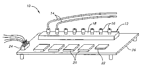
Referring to Figure ~1, the light testing module 10 of the
present invention consists of an assembly of sensors 12 to
which the light from the emitter under test is presented. In
the implementation shown, the light is piped to the sensors
using fiber optic cables) 14 connecting to the sensors using
plastic fiber connectors) 16. The sensors are located under
a light shield 18 to prevent entrance of ambient light.
Electronics 20 on the assembly condition the sensor signals,
process the red, green, and blue components of the light, and
produce wavelength and intensity outputs. Additional
electronics 22 is provided to select one of n sensors on the
module corresponding to the light-emitter currently under
test. A connector 24 is provided for wiring the test module
to automatic test apparatus to provide power for operation,
one of n sensor selection, and output values. All of the
components of the test module 10 can be mounted on a printed
circuit board 26 or other suitable device.
Figure 2 is a detail view of the termination of the fiber
optic cable 14 at the light emitting device 28 to be tested.
An end of the flexible plastic optical fiber 14 is encased in
a rigid tube 30 to provide pointing accuracy to the device
under test 28 mounted on a printed circuit board 32. The
. fiber optic cable is cut flush with the end of the tube 30,
and held in position using adhesive backed heat shrink tubing
to hold the fiber in position in the tube. The supporting
tube is mounted rigidly, preferably by an adhesive 34, to a
plate 36 to provide centering of the assembly at the optical
-4-
CA 02456941 2004-02-04
center of the device under test 28, as well as providing a
minimal spacing from the device to prevent damage to the fiber
or device under test. A connector 38 is positioned on an end
of the tube 30. The numerical aperture (acceptance angle) of
the optical fiber is such that a portion of the emitted light
is collected by the fiber, dependent on the viewing angle of
the light-emitting device under test, and the spacing of the
. fiber from the light-emitting device. Since color
determination is accomplished using ratios of the primary
colors, the percentage of the total light collected is not
critical to the measurement.
While this particular implementation uses fiber optics to
couple the light, alternatively, similar modules could be
. implemented where the light sensor is mounted at the light
emitter under test, and electrically connected to the
electronics on the test module for processing.
Referring to the schematic in Figure 3, the individual
color photodiodes 40a, 40b and 40c which comprise the sensors
42 are amplified 44 then selected by an analog multiplexer 46.
The analog signals are then digitized by the analog to digital
converter 48. Two digital to analog converters 50 and 52
convert the calculated values of wavelength and~intensity from
the microprocessor 54 to analog values which can be read back
to the automatic test apparatus 56 for pass/fail comparison.,
The preprogrammed microprocessor 54 performs calculations
to determine intensity, and wavelength of the incoming light.
Luminous intensity is calculated as a function of the total
energy captured by the red, green and blue photodiodes,
factored by the preconditioning and equalization which has
been done. First, tests are run to determine if sufficient
light intensity is present to process. Below the present
limit, the processing will terminate, and zero volts
_5_
CA 02456941 2004-02-04
programmed to both the intensity and wavelength analog to
digital converters to indicate no useable signal is present.
If the low limit tests pass, tests are then performed to
check for equality of all three color components for white
light determination. Tf the red, green, and blue components
are equal within a preset percentage, color calculations are
skipped, and the wavelength output value is set to a
predetermined output voltage level which indicates a white
source is present.
If the test indicates the light is monochromatic, the
color processing is run, first determining the order of the
color by decreasing magnitude. Based on this order, sets of
algorithms to calculate the wavelength are called. These
algorithms calculate the wavelength by mathematical operations
which convert the red, green, and blue magnitudes into
wavelength based on the CIE color conversion values for human
perception of color, as shown in the gfaph of Figure 4.
The chart shown in Figure 5, shows the ratio of the red,
green and blue color mix throughout the visible range. These
ratios alternatively are calculated based on the levels
present at the sensors, and used as an index into lookup
tables contained in the microprocessor memory:v These tables
correlate the ratios of,red, green, and blue directly into the
equivalent wavelength in nanometers. The wavelength 'is
converted to a scaled voltage, which is then output by the
digital to analog converter.
Once the wavelength is determined, a digital value is
output to the digital to analog converter, which represents a
direct voltage match to the calculated wavelength. For
. instance, 550 manometers would output 550 milivolts, or a
multiple of that value, to make the voltage more readable by
the automatic test system.
-6-
CA 02456941 2004-02-04
Additional inputs 58 to the module are provided for
digital selection of the sensor to be addressed, as well as
power to run the module.
The sensor or sensors are capable of detecting the
content of red, green, and blue or the complements cyan,
yellow and magenta, to allow for the weighing of the
individual colors to determine the wavelength of an incoming
beam. The sensor can be a monolithic tricolor sensor, or
individual filtered photodiode sensors with the optics to
disperse the light equally across the three sensors. The
colors are not limited to three and can be any number or
color, required to effectively differentiate the incoming
wavelength. The test module has the capability of selecting
the individual sensor, the processing capability to calculate
the wavelength from the levels of the sensed colors, and an
output interface to present the wavelength data to the
automatic test equipment in a digital or analog form.
In one embodiment, the multi-color sensor and
amplification or a plurality of sensors and amplifiers are
mounted remotely, at the light emitting-device under test, and
electrically connected to the remainder of the electronic
processing. Alternatively, the multi-color' sensor or a
plurality of sensors can be mounted with the processing
circuitry, for use with fiber optic cables used to collect the
light from the light-emitting device under test and transmit
the light signals to the sensors. The test module uses a
predefined set of color ratios based on standard color
w matching tables, modified by sensor response, to determine
wavelength by comparing the color ratios of the incoming light
irrespective of the absolute values. The test module which
provides a calculated wavelength output, based on the
proportion of the content of colors detected in the light
_~_
CA 02456941 2004-02-04
output of a monochromatic emitting device.
The test module also determines a white source from a
light-emitting device when all of the color sensor levels
contribute equally to total input. The test module converts
the input light to an analog signal scaled directly from
nanometers to milivolts or a multiple thereof throughout the
visible spectrum of 380nm to 7OOnm, and uses a unique voltage
~ level in excess of the range of visible spectrum converted
voltages to denote the detection of a white source.
20
30
.g_