Sélection de la langue

Search

Sommaire du brevet 2457380 

Énoncé de désistement de responsabilité concernant l'information provenant de tiers

Une partie des informations de ce site Web a été fournie par des sources externes. Le gouvernement du Canada n'assume aucune responsabilité concernant la précision, l'actualité ou la fiabilité des informations fournies par les sources externes. Les utilisateurs qui désirent employer cette information devraient consulter directement la source des informations. Le contenu fourni par les sources externes n'est pas assujetti aux exigences sur les langues officielles, la protection des renseignements personnels et l'accessibilité.

Disponibilité de l'Abrégé et des Revendications

L'apparition de différences dans le texte et l'image des Revendications et de l'Abrégé dépend du moment auquel le document est publié. Les textes des Revendications et de l'Abrégé sont affichés :

  • lorsque la demande peut être examinée par le public;
  • lorsque le brevet est émis (délivrance).
(12) Demande de brevet: (11) CA 2457380
(54) Titre français: SCOOTER ELECTRIQUE PLIANT ET PORTATIF
(54) Titre anglais: FOLDING AND PORTABLE ELECTRIC SCOOTER
Statut: Réputée abandonnée et au-delà du délai pour le rétablissement - en attente de la réponse à l’avis de communication rejetée
Données bibliographiques
(51) Classification internationale des brevets (CIB):
  • B62K 15/00 (2006.01)
(72) Inventeurs :
  • LEE, SHUEI-YUAN (Taïwan, Province de Chine)
(73) Titulaires :
  • AN NEW INDUSTRIAL CO., LTD.
(71) Demandeurs :
  • AN NEW INDUSTRIAL CO., LTD. (Taïwan, Province de Chine)
(74) Agent: ROBIC AGENCE PI S.E.C./ROBIC IP AGENCY LP
(74) Co-agent:
(45) Délivré:
(22) Date de dépôt: 2004-02-11
(41) Mise à la disponibilité du public: 2005-08-11
Licence disponible: S.O.
Cédé au domaine public: S.O.
(25) Langue des documents déposés: Anglais

Traité de coopération en matière de brevets (PCT): Non

(30) Données de priorité de la demande: S.O.

Abrégés

Abrégé anglais


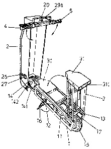
A folding and portable electric scooter assembled from structural
members including a body member, a cover member, a seat frame and
handles. When the electric scooter is not in use, a user needs only employ
three simple actions to facilitate rapid folding away and realize formation
of a portable electric scooter, namely to fold down handles into the cover
member, and fold away the cover member and the seat frame into the body
member, whereupon, the user can pull on a pull rod configured atop the
cover member to effortlessly pull along the electric scooter by means of
auxiliary wheels connected to the body member, similar to pulling along of
baggage. When the user wishes to ride the electric scooter, the user needs
only to implement three simple maneuvers to open up the folded electric
scooter, namely to pull open the cover member, the seat frame and the
handles, whereupon the cover member instantly forms a front frame, of the
electric scooter. Thereupon, the user can switch on electrical power and
thus enable the user to ride the electric scooter. The front frame formed by
the cover member also actualizes functionality as a shield from wind and
rain.

Revendications

Note : Les revendications sont présentées dans la langue officielle dans laquelle elles ont été soumises.


What is claimed is:
1. A folding and portable electric scooter comprising a body member, a
cover member, a seat frame and two handles, wherein interior of the
body member is installed a transmission device comprising an electric
motor, a battery and a belt; a front wheel and a rear wheel are pivot
jointed to a front and rear end of the body member respectively, and a
foot stand is fixedly positioned to a side of the body member; the electric
motor drives the belt, and the belt wraps roved a hub at a side of the rear
wheel; and is characterized in that:
the cover member is pivot jointed to a wheel frame of the front wheel,
and the two handles are configured on a moveable end of the cover
member; an reverse U-shaped bracket is bolted onto the cover member,
and an reverse U-shaped fastening bracket is configured atop the reverse
U-shaped bracket; each end of the fastening bracket is downwardly bent
to respectively form a neck, and a fastening hook is respectively
configured on each of the necks thereof, fastening holes defined in
handle bars provide for the fastening hooks of the fastening bracket to
hook and fasten position thereinto; a recess hole is defined on each of
two ends atop the fastening bracket, and a fixing bolt is bolted into each
of the recess holes, moreover, the fastening bracket utilizes the fixing
bolts to alter position within the recess holes, and thereby facilitate
fastening down or loosening of the handles; upon the electric scooter
being folded away, the cover member completely covers the body
member, and when the electric scooter is in usage, the cover member
functions as a front frame for the electric scooter;
-8-

a seat is installed atop the seat frame configured at a tail end of the body
member, and the seat frame can be folded away into the body member; a
bar is respectively bolted to each of two front sides of the seat frame, and
a movable strip is configured interior of each of the bars, a holding bar is
configured between and joins extremities of the two moveable strips; a
hook eye is respectively defined in each of the bars and provide for
inclined wedge pieces to respectively fasten thereinto; a spring is
connected to an underside of each of the wedge pieces; pushing down on
the holding bar thereby enables the moveable strips to outwardly push
the wedge pieces, and thus separate the wedge pieces from being
fastened in the hook eyes, whereupon the seat frame can be folded down,
if the seat frame is lightly pulled back to an upright position, a fastening
is utilized to fix position and thereby enable formation of a seat.
2. The folding and portable electric scooter in accordance with claim 1,
wherein a foldaway carry handle is configured on top of the cover
member, a headlight is configured at a side of the carry handle; a power
switch and a battery charge switch cover are configured on a side face of
the cover member, and a folding panel is configured on a frontal section
at a tail end of the cover member.
3. The folding and portable electric scooter in accordance with claim 1,
wherein a brake device is bolted to the handle, and the brake is
connected to a braking system by means of a brake cable.
4. The folding and portable electric scooter in accordance with claim 1,
wherein a loose pull-bar is configured on a back of the cover member,
and upwardly pulling on the loose pull-bar tugs on two pull cables,
-9-

whereupon the two pull cables respectively actuate two fastening hooks
to disengage fastening from a locating hole of the wheel frame of the
front wheel of the cover member and a fastening edge of a rear wheel
frame of the body member, thereby opening up the electric scooter;
when folding away the electric scooter, pulling up on the loose pull-bar
tugs the two pull cables, and actuates the fastening hook to disengage
fastening from the locating hole, thereby enabling folding away of the
front frame.
5. The folding and portable electric scooter in accordance with claim 1,
wherein two auxiliary wheels are configured on a frontal section of the
front wheel of the body member, and a pull rod is configured on a frontal
section of the cover member, upon folding away, pulling on the pull rod
thereby enables the electric scooter to be pulled along ground by means
of the auxiliary wheels.
6. The folding and portable electric scooter in accordance with claim 1,
wherein a brake light is configured at a rear of the seat installed atop the
seat frame.
-10-

Description

Note : Les descriptions sont présentées dans la langue officielle dans laquelle elles ont été soumises.


CA 02457380 2004-02-11
FOLDING AND PORTABLE ELECTRIC SCOOTER
BACKGROUND OF THE INVENTION
(a) Field of the Invention
The present invention relates to a scooter, and more particularly to an
electric scooter that can be folded away into a baggage-like form which can
be carried or auxiliary wheels configured on the electric scooter can be
utilized to enable a user to pull along and thereby transport the electric
scooter for easy portability.
(b) Description of the Prior Art
1o A majority of conventional electric scooters cannot be folded away into a
baggage-like form, thus when transporting the electric scooter cannot be
neatly put away or carried along when traveling on a rapid transit
transportation system, and so on. Moreover, bulkiness of the electric
scooter makes transporting of the electric scooter difficult.
SUMMARY OF THE INVENTION
A primary objective of the present invention is to provide a configuration
that employs three simple actions to facilitate rapid folding away and
realizes formation of a portable electric scooter. Prior to usage, the
electric
scooter can be folded away and thus form a reduced size baggage-like form
2o which can be carried or auxiliary wheels configured on the electric scooter
can be utilized to enable a user to pull along the electric scooter onto a
rapid transit system or facilitate transport storage thereof. When the user
wishes to ride the electric scooter, the user needs only to implement three
simple maneuvers to open up the folded scooter, namely to pull open a
cover member, a seat frame and handles, thereby quickly assembling the

CA 02457380 2004-02-11
electric scooter ready for the user to ride thereon. Wherein the cover
member instantly forms a front frame of the electric scooter, and apart from
actualizing functionality as a shield from wind and rain, also provides for
an attractive appearance after folding away of the configuration.
Another objective of the present invention is provide a structure with two
., auxiliary wheels respectively configured an outer sides of a front wheel of
a body member, and a pull rod configured on a front edge of a cover
member, whereby, when the present invention has been folded away to
form a baggage-like form, pulling on the pull rod by the user enables
1o effortlessly pulling along of the electric scooter by means of the
auxiliary
wheels, similar to pulling along of baggage.
To enable a further understanding of the said objectives and the
technological methods of the invention herein, the brief description of the
drawings below is followed by the detailed description of the preferred
embodiments.
BRIEF DESCRIPTION OF THE DRAWINGS
FIG. I shows a general view of an electric scooter after folding away
according to the present invention.
FIG. 2 shows a general view of the electric scooter after opening up
2o according to the present invention.
FIG. 3 shows a partial structural view of a seat frame and a body
member according to the present invention.
FIG. 4 shows a schematic side view of the seat frame and the body
member according to the present invention.
FIG. 5 shows a structLUal view of a cover member and handles according
-2-

CA 02457380 2004-02-11
to the present invention.
FIG. 6 shows a partial structural view of the cover member lifted up
according to the present invention.
FIG. 7 shows another partial structural view of the cover member lifted
up according to the present invention,
FIG. 8 shows a structural view of A-section of FIG. 6 according to the
present invention.
FIG. 9 shows a structural view of B-section of FIG. 7 according to the
present invention.
1o FIG. 10 shows a schematic view of an embodiment according to the
present invention.
DETAILED DESCRIPTION OF THE PREFERRED
EMBODIMENTS
Referring to FIGS. 1 and 2, which show structural members of an
electric scooter of the present invention primarily comprising a body
member 1, a cover member 2, a seat frame 3 and two handles 4 and 5.
Wherein the body member 1 comprises a rectangular frame, interior of
which is installed a transmission device comprising an electric motor 11, a
battery 12 and a belt 13. A front wheel 14 and a rear wheel 15 are pivot
2o jointed to a front and rear end of the body member 1 respectively. A foot
stand 16 is fixedly positioned to a side of the body member 1, The electric
motor 11 drives the belt 13, and the belt 13 wraps round a hub at a side of
the rear wheel 15. The aforementioned transmission device is of
conventional structure, while the present invention is characterized in that:
A wheel frame 141 of the front wheel 14 is pivot jointed to the cover
-3-

CA 02457380 2004-02-11
member 2 by means of a bolt 142, and the cover member 2 is adapted to
assume an reverse U-shaped frame cover, therewith enabling complete
covering of the body member 1 (see FIGS. 1 and 2). The two handles 4 and
are configured on a moveable end of the cover member 2. As depicted in
s FIG. 5, a reverse U-shaped bracket 22 is bolted onto the cover member 2
by means of screws 21. A reverse U-shaped fastening bracket 23 is
configured atop the reverse U-shaped bracket 22. Each end of the fastening
bracket 23 is downwardly bent to respectively form a neck, and a fastening
hook 231 is respectively configured on each of the necks thereof. Trumpet-
to shaped fastening holes 411 and 511 are defined in handlebars 41 and 51.
The fastening holes 411 and 511 provide for the fastening hooks 231 of the
fastening bracket 23 to hook and fasten position thereinto. A trumpet-
shaped recess hole 232 is defined on each of two ends atop the fastening
bracket 23. A fixing bolt 233 is bolted into each of the recess holes 232,
and fixes position therein. The fastening bracket 23 utilizes the fixing bolts
233 to alter position within the recess holes 232, and thereby facilitate
fastening down or loosening of the two handles 4 and 5. Upon the handles
4 and 5 being loosened, the handles 4 and 5 can thereby be folded down
and stored within the cover member 2.
Referring to FIGS. 3 and 4, a seat 31 is installed atop the seat frame 3
configured at a tail end of the body member 1, and a brake light 311 is
configured at a rear of the seat 31 (see FIG. 2). The seat frame 3 can be
folded flat within the body member 1, and can be pulled back to an upright
position thereby enabling a rider to sit atop the seat 31. Folding structure
of
the seat frame 3 comprises a C-shaped bar 32 respectively bolted to each of
-4-

CA 02457380 2004-02-11
two front sides of the seat frame 3. A movable strip 321 is configured
interior of each of the bars 32, and a holding bar 322 is configured between
and joins extremities of the two moveable strips 321. A hook eye 323 is
appropriately defined center of each of the bars 32 respectively, and the
hook eyes 323 respectively provide for inclined wedge pieces 324 to
respectively fasten thereinto. A spring 3241 is connected to an underside of
each of the wedge pieces 324. Referring to FIG. 4, when a user wishes to
fold away the seat frame 3, the user needs only to firmly grasp the holding
bar 322 and push down, thereby enabling the moveable strips 321 to
outwardly push the wedge pieces 324, and thus separate the wedge pieces
324 from being fastened in the hook eyes 323, whereupon the entire seat
frame 3 is thereby enabled to be folded down and concealed within the
body member 1.
Referring to FIG. l, a foldaway carry handle 24 is configured on top of
the cover member 2, wherewith enables the present invention to be lifted
by hand. A headlight 25 is configured at a side of the carry handle 24, and a
power switch 26 and a battery charge switch cover 27 are configured on a
side face of the cover member 2. A three-fold panel is configured on a
frontal section at a tail end of the cover member 2, therewith enabling
2o covering of a frontal end of the body member 1. Referring to FIG. 5, a
power indicator light 296 is configured on an end of the cover member 2
close to the handle 4. A brake 42 is bolted to the handle 4, and the brake 42
is connected to a braking system by means of a brake cable (see FIGS. 6
and 7). A loose pull-bar 29 is configured on a back of the cover member 2,
and referring to FIG. 6, the user can upwardly pull on the loose pull-bar 29,
-5-

CA 02457380 2004-02-11
whereupon the loose pull-bar 29 having a spring 291 configured therein
tugs on two pull cables 292 and 293, thus enabling a fastening hook 294 to
disengage fastening from a locating hole 2941 of the front wheel frame 141
of the cover member 2 (see FIG. 9), while another fastening hook 295
disengages fastening from a fastening edge 17 of a rear wheel frame of the
body member 1 (see FIG. 8). FIG. 2 shows the electric scooter opened up,
whereupon the cover member 2 instantly forms a front frame of the electric
scooter, and actualizes functionality as a shield from wind and rain similar
to a conventional motor scooter.
1 o Furthermore, two auxiliary wheels 18 are provided on a frontal section
of the front wheel 14 of the body member 1 (see FIG. 1). A foldaway pull
rod 20 is configured on a frontal section of the cover member 2 (see FIG.
2). Upon the present invention being folded and thus forming a baggage-
like form, as FIG. 10 shows, the user can pull on the pull rod 20, and
ns- thereby enable the scooter to be pulled along ground by means of the
auxiliary wheels l8.similar to pulling along of baggage.
In conclusion, the present invention employs three simple actions to
facilitate rapid folding away and formation of a baggage-like body that is
portable or utilizes the configured auxiliary wheels 18 to enable the user to
2o pull along the scooter into rapid transit transportation stations, and so
on.
The electric scooter of the present invention thus provides for
transportability and easy storing thereof. Hence, when the user wishes to
ride the scooter, the user needs only to implement three simple maneuvers
to open up the folded scooter, namely to pull open the cover member 2, the
25 seat frame 3 and the two handles 4 and 5, thereby quickly assembling the
-6-

CA 02457380 2004-02-11
electric scooter for the user to ride thereon.
It is of course to be understood that the embodiments described herein is
merely illustrative of the principles of the invention and that a wide variety
of modifications thereto may be effected by persons skilled in the art
without departing from the spirit and scope of the invention as set forth in
the following claims.
.7_

Dessin représentatif
Une figure unique qui représente un dessin illustrant l'invention.
États administratifs

2024-08-01 : Dans le cadre de la transition vers les Brevets de nouvelle génération (BNG), la base de données sur les brevets canadiens (BDBC) contient désormais un Historique d'événement plus détaillé, qui reproduit le Journal des événements de notre nouvelle solution interne.

Veuillez noter que les événements débutant par « Inactive : » se réfèrent à des événements qui ne sont plus utilisés dans notre nouvelle solution interne.

Pour une meilleure compréhension de l'état de la demande ou brevet qui figure sur cette page, la rubrique Mise en garde , et les descriptions de Brevet , Historique d'événement , Taxes périodiques et Historique des paiements devraient être consultées.

Historique d'événement

Description Date
Demande non rétablie avant l'échéance 2008-02-11
Le délai pour l'annulation est expiré 2008-02-11
Réputée abandonnée - omission de répondre à un avis sur les taxes pour le maintien en état 2007-02-12
Inactive : Page couverture publiée 2005-08-19
Demande publiée (accessible au public) 2005-08-11
Lettre envoyée 2004-05-19
Inactive : CIB en 1re position 2004-05-12
Inactive : Transfert individuel 2004-04-30
Inactive : Lettre de courtoisie - Preuve 2004-03-23
Inactive : Certificat de dépôt - Sans RE (Anglais) 2004-03-17
Demande reçue - nationale ordinaire 2004-03-16

Historique d'abandonnement

Date d'abandonnement Raison Date de rétablissement
2007-02-12

Taxes périodiques

Le dernier paiement a été reçu le 2006-02-13

Avis : Si le paiement en totalité n'a pas été reçu au plus tard à la date indiquée, une taxe supplémentaire peut être imposée, soit une des taxes suivantes :

  • taxe de rétablissement ;
  • taxe pour paiement en souffrance ; ou
  • taxe additionnelle pour le renversement d'une péremption réputée.

Les taxes sur les brevets sont ajustées au 1er janvier de chaque année. Les montants ci-dessus sont les montants actuels s'ils sont reçus au plus tard le 31 décembre de l'année en cours.
Veuillez vous référer à la page web des taxes sur les brevets de l'OPIC pour voir tous les montants actuels des taxes.

Historique des taxes

Type de taxes Anniversaire Échéance Date payée
Taxe pour le dépôt - petite 2004-02-11
Enregistrement d'un document 2004-04-30
TM (demande, 2e anniv.) - petite 02 2006-02-13 2006-02-13
Titulaires au dossier

Les titulaires actuels et antérieures au dossier sont affichés en ordre alphabétique.

Titulaires actuels au dossier
AN NEW INDUSTRIAL CO., LTD.
Titulaires antérieures au dossier
SHUEI-YUAN LEE
Les propriétaires antérieurs qui ne figurent pas dans la liste des « Propriétaires au dossier » apparaîtront dans d'autres documents au dossier.
Documents

Pour visionner les fichiers sélectionnés, entrer le code reCAPTCHA :


Pour visualiser une image, cliquer sur un lien dans la colonne description du document (Temporairement non-disponible). Pour télécharger l'image (les images), cliquer l'une ou plusieurs cases à cocher dans la première colonne et ensuite cliquer sur le bouton "Télécharger sélection en format PDF (archive Zip)" ou le bouton "Télécharger sélection (en un fichier PDF fusionné)".

Liste des documents de brevet publiés et non publiés sur la BDBC .

Si vous avez des difficultés à accéder au contenu, veuillez communiquer avec le Centre de services à la clientèle au 1-866-997-1936, ou envoyer un courriel au Centre de service à la clientèle de l'OPIC.

({010=Tous les documents, 020=Au moment du dépôt, 030=Au moment de la mise à la disponibilité du public, 040=À la délivrance, 050=Examen, 060=Correspondance reçue, 070=Divers, 080=Correspondance envoyée, 090=Paiement})


Description du
Document 
Date
(aaaa-mm-jj) 
Nombre de pages   Taille de l'image (Ko) 
Revendications 2004-02-10 3 123
Abrégé 2004-02-10 1 34
Description 2004-02-10 7 283
Dessins 2004-02-10 6 114
Dessin représentatif 2005-07-13 1 11
Certificat de dépôt (anglais) 2004-03-16 1 158
Courtoisie - Certificat d'enregistrement (document(s) connexe(s)) 2004-05-18 1 106
Rappel de taxe de maintien due 2005-10-11 1 109
Courtoisie - Lettre d'abandon (taxe de maintien en état) 2007-04-09 1 174
Correspondance 2004-03-16 1 25
Correspondance 2004-04-29 3 86
Taxes 2006-02-12 1 33