Sélection de la langue

Search

Sommaire du brevet 2457929 

Énoncé de désistement de responsabilité concernant l'information provenant de tiers

Une partie des informations de ce site Web a été fournie par des sources externes. Le gouvernement du Canada n'assume aucune responsabilité concernant la précision, l'actualité ou la fiabilité des informations fournies par les sources externes. Les utilisateurs qui désirent employer cette information devraient consulter directement la source des informations. Le contenu fourni par les sources externes n'est pas assujetti aux exigences sur les langues officielles, la protection des renseignements personnels et l'accessibilité.

Disponibilité de l'Abrégé et des Revendications

L'apparition de différences dans le texte et l'image des Revendications et de l'Abrégé dépend du moment auquel le document est publié. Les textes des Revendications et de l'Abrégé sont affichés :

  • lorsque la demande peut être examinée par le public;
  • lorsque le brevet est émis (délivrance).
(12) Demande de brevet: (11) CA 2457929
(54) Titre français: COMMUTATEUR DE LIGNE INTELLIGENT
(54) Titre anglais: INTELLIGENT LINE SWITCH
Statut: Réputée abandonnée et au-delà du délai pour le rétablissement - en attente de la réponse à l’avis de communication rejetée
Données bibliographiques
(51) Classification internationale des brevets (CIB):
  • H01H 36/00 (2006.01)
  • H01H 9/02 (2006.01)
  • H03K 17/95 (2006.01)
  • H03K 17/955 (2006.01)
  • H03K 17/96 (2006.01)
(72) Inventeurs :
  • WEI, JUNG T. (Taïwan, Province de Chine)
(73) Titulaires :
  • JUNG T. WEI
(71) Demandeurs :
  • JUNG T. WEI (Taïwan, Province de Chine)
(74) Agent: BULL, HOUSSER & TUPPER LLP
(74) Co-agent:
(45) Délivré:
(22) Date de dépôt: 2004-02-11
(41) Mise à la disponibilité du public: 2004-08-21
Requête d'examen: 2004-10-27
Licence disponible: S.O.
Cédé au domaine public: S.O.
(25) Langue des documents déposés: Anglais

Traité de coopération en matière de brevets (PCT): Non

(30) Données de priorité de la demande:
Numéro de la demande Pays / territoire Date
03105468 (Chine) 2003-02-21

Abrégés

Abrégé anglais


An intelligent line switch and particularly a line switch equipped with an
approaching or touching sensor, and an adjusting knob with a sensor of
adjusting sensitivity. The line switch includes a switch operable in a manual
mode or an automatic mode. The manual mode may control an electric
device in a conventional way. When switched to the automatic mode, the
sensor can detect approaching or touching of operator's hand. Thus operator
can easily actuate operations of ON or OFF or adjustment of the electric
device by merely a single motion such as approaching or touching with one
hand without the complicated operations of approaching, grasping,
depressing and leaving occurred to the conventional line switches.

Revendications

Note : Les revendications sont présentées dans la langue officielle dans laquelle elles ont été soumises.


I claim:
1. An intelligent line switch comprising a shell and a control device housed
in the shell, the control device including an inductive circuit which has a
sensor sensible to approaching or touching of an object, the control
device being connected to one end of a power cord which further
connects to a load through the control device;
wherein the control device controls ON or OFF of the load through a
single motion when an operator's hand approaches or touches the sensor.
2. The intelligent line switch of claim 1, wherein the power cord connects
to a common contact of a selection switch for an automatic and a manual
control modes before connecting to the control device, the automatic
control mode having a first contact connecting to the control device, the
manual control mode having a second contact connecting to a third
contact located on one end of a button switch, the button switch having a
fourth contact connecting concurrently to an output control end of the
control device and the load.
3. The intelligent line switch of claim 1, wherein the shelf is made from
metal or selected conductive materials, the inductive circuit of the
control device being connected to the shell so that the shell has induction
20 capability to substitute the sensor.
9

Description

Note : Les descriptions sont présentées dans la langue officielle dans laquelle elles ont été soumises.

CA 02457929 2004-02-11
INTELLIGENT LINE SWITCH
BACKGROUND OF THE INVENTION
1. Field of the Invention
S The invention relates to a line switch equipped with an approaching or
touch sensor for controlling electric devices by induction or also equipping
conventional depressing operation.
2. Description of the Prior Art
The commonly used switches for controlling electric devices can be
l0 classified in wall switches, pulling switches, device switches directly
mounted onto the electric devices or line switches installed on the power
cord.
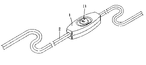
The line switch 1, as shown in FIGS. 1 and 2, generally is installed on a
power cord 2 that provides power supply to the electric device. It includes a
button switch 11. Depressing the button switch 11 can control ON or OFF of
15 the electric device.
The line switch set forth above adopts conventional manual operation.
The operation usually includes the following steps:
1. Hand approaches the line switch 1 (as shown in FIG. 3) and prepares

CA 02457929 2004-02-11
to grasp the line switch 1.
2. Hand grasps the line switch 1 (as shown in FIG. 4) and prepares to
depress the button switch 11.
3. Thumb moves to the button switch 11 and depresses the button
switch 11 (as shown in FIG. 5) to control or adjust ON or OFF of the
electric device.
4. Finally, the thumb releases and the palm opens, the hand moves
away from the line switch 1 (as shown in FIG. 6).
It takes many steps to operate and control the line switch 1. The
operation procedures of hand grasping and finger depressing are primitive
and cumbersome. They cannot achieve the control function instantly. In the
event that the line switch 1 is suspended in the air, it tends to swing and is
difficult to grasp. Moreover, some conventional line switch 1, besides
offering the function of switching ON or OFF of the electric device, also can
adjust light brightness or intensity of the electric device. The operation
procedures of the button switch cannot fully meet such requirements.
SIt~vIMA.RY OF THE INVENTION
In view of the aforesaid disadvantages, the primary object of the
invention is to provide an intelligent line switch that achieves control
z

CA 02457929 2004-02-11
function in a simple and easy way to overcome the troubles and
inconveniences of conventional line switches that involve the operations of
approaching, grasping, depressing and leaving. According to the invention,
the shell of the Line switch houses an approaching or touch sensor to enable
the line switch to equip approaching or touch control capability. When an
user's hand approaches or touches the Line switch, the sensor detects the
approaching or touching hand, and can control or adjust ON or OFF of the
electric device.
In one aspect of the invention, the line switch of the invention includes a
manual/automatic mode switch to integrate the conventional button switch
function so that the line switch may be selectively operated in the
conventional button switch mode or the induction mode to control the electric
device. The line switch thus constructed includes dual control functions.
In another aspect, the shell of the line switch may be made from metal or
conductive plastics or other conductive materials with an inductive circuit
connecting to the shell so that the shell also has induction capability. When
human body approaches or touches the shell, the electric device may also be
controlled.
In yet another aspect, a mufti-stage control and adjustment of the electric
device may be achieved by the distance of approaching hand or frequency or
the elapsed time of the hand in contact with the touch sensor.
The foregoing, as well as additional objects, features and advantages of
3

CA 02457929 2004-02-11
the invention will be more readily apparent from the following detailed
description, which proceeds with reference to the accompanying drawings.
BRIEF DESCRIPTION OF THE DRAWINGS
FIG. 1 is a perspective view of a conventional line switch.
FIG. 2 is a schematic circuit diagram of a conventional line switch.
FIG. 3 is a schematic view of a conventional line switch in an operating
condition.
FIG. 4 is a schematic view of a conventional line switch in another
IO operating condition.
FIG. S is a schematic view of a conventional line switch in yet another
operating condition.
FIG. 6 is a schematic view of a conventional line switch in still another
operating condition.
15 FIG. 7 is a perspective view of the invention.
FIG. 8 is a schematic circuit diagram of the line switch of the invention.
FIG. 9 is a perspective view of a second embodiment the invention.
FIG. IO is a schematic circuit diagram of the second embodiment the
invention.
4

CA 02457929 2004-02-11
FIG. 11 is a perspective view of a third embodiment the invention.
FIG. 12 is a schematic circuit diagram of the third embodiment the
invention.
FIG. 13 is a block diagram of a control device of the invention.
S FIG. 14 is a block diagram of another embodiment of the control device
of the invention.
DESCRIPTION OF THE PREFERRED EMBODIMENTS
Referring to FIGS. 7 and 8, the line switch 3 of the invention includes a
control device 6 located in a shell. The control device 6 has an inductive
circuit. The inductive circuit has a sensor 31 sensible to approaching or
touching of human body. The power cord 4 has one end connecting to the
control device 6, then through the control device 6 connects to a load 5.
When a user's hand approaches or touches the sensor 31 of the line switch 3,
the sensor 31 transmits the detected signal to the control device 6 which
controls ON or OFF of the electric device. Thus user does not need to take
the complicated operation steps of approaching, grasping, depressing and
leaving that occur to the conventional button Iine switch. Merely through
the movement or posture of an approaching hand, the electric device may be
controlled. Thus operation of the line switch 3 is much simpler and easier.
5

CA 02457929 2004-02-11
Referring to FIGS. 9 and 10 for another embodiment of the invention,
the shell of the line switch 3 also includes a control device 6 which has a
sensor 31 sensible to approaching or touching of human body. In addition,
the line switch 3 includes a selection switch 32. The power cord 4 has one
S end connecting to the selection switch 32. The selection switch 32 has a
contact B (for automatic control mode) connecting to the control device 6 and
another contact A (for manual control mode) connecting to the contact of the
original button switch 33 of the line switch 3. The original button switch 33
has another contact connecting to an output control end of the control device
6 and the load 5. Hence when the selection switch 32 is switched to the
contact B, the line switch 3 is in the induction control mode. When the
selection switch 32 is switched to the contact A, it is in the manual control
mode and the original button switch 33 may be used to control ON or OFF of
the load 5. By means of such a structure, the line switch 3 can integrate and
concurrently equip manual and automatic control methods.
Referring to FIGS. 11 and 12 for yet another embodiment of the
invention for the line switch 3 to integrate the conventional line switch 1
that
equips with a button switch 11 and the induction control function. The line
switch 3 of the invention includes a sensor 31 and a selection switch 32. The
contact A of the selection switch 32 and the output control end of the control
device 6 connect to two contacts of the switch of the line switch 1. Thus the
6

CA 02457929 2004-02-11
conventional line switch 1 has inductive line switch 3 simultaneously.
Therefore the original conventional line switch 1 also has inductive control
functi on.
Referring to FIG. 13 for the control method of the control device 6. It
mainly includes a control unit 61 and a sensor unit 62. The control unit 61
mainly consists of a power supply circuit, a control circuit and a gate switch
circuit. 'The sensor unit 62 includes an induction circuit and a sensor 31. To
equip the manual and automatic control modes concurrently on the line
switch, two ends of the gate switch circuit are connected to a selection
switch
32 and a button switch 33. Or as shown in FIG. 14, the inductive line switch
of the invention originally has a sensor 31 to detect the approaching or
touching of human body. The sensor 31 may be removed, and with the
induction circuit directly connecting to the shell of the line switch 3 that
is
made from metal, or conductive plastics, or other conductive materials so that
1 S the shell becomes an inductive element with inductive capability. Thus
when
human body approaches the shell, the electric device may be inducted to
accomplish the control object.
Furthermore, the control device 6 of the invention may also include a
radio control device to enable the line switch 3 to control a remote load in a
remote fashion. In addition, through hand approaching or touching frequency
or elapsed time of touching on the sensor 31, a multiple-stage control or

CA 02457929 2004-02-11
adjustment may be made for the electric device.
In summary, the invention overcomes the troubles of approaching,
grasping, depressing and leaving operations occurred to conventional line
switches, and controls electric devices by simply approaching the line switch
S in a short distance or touching the line switch. The operation and control
is
much simpler and easier.
While the preferred embodiments of the invention have been set forth for
the purpose of disclosure, modifications of the disclosed embodiments of the
invention as well as other embodiments thereof may occur to those skilled in
the art. Accordingly, the appended claims are intended to cover all
embodiments which do not depart from the spirit and scope of the invention.
s

Dessin représentatif
Une figure unique qui représente un dessin illustrant l'invention.
États administratifs

2024-08-01 : Dans le cadre de la transition vers les Brevets de nouvelle génération (BNG), la base de données sur les brevets canadiens (BDBC) contient désormais un Historique d'événement plus détaillé, qui reproduit le Journal des événements de notre nouvelle solution interne.

Veuillez noter que les événements débutant par « Inactive : » se réfèrent à des événements qui ne sont plus utilisés dans notre nouvelle solution interne.

Pour une meilleure compréhension de l'état de la demande ou brevet qui figure sur cette page, la rubrique Mise en garde , et les descriptions de Brevet , Historique d'événement , Taxes périodiques et Historique des paiements devraient être consultées.

Historique d'événement

Description Date
Demande non rétablie avant l'échéance 2008-02-11
Le délai pour l'annulation est expiré 2008-02-11
Inactive : Abandon. - Aucune rép dem par.30(2) Règles 2007-06-13
Réputée abandonnée - omission de répondre à un avis sur les taxes pour le maintien en état 2007-02-12
Inactive : Dem. de l'examinateur par.30(2) Règles 2006-12-13
Inactive : CIB de MCD 2006-03-12
Lettre envoyée 2004-11-08
Exigences pour une requête d'examen - jugée conforme 2004-10-27
Toutes les exigences pour l'examen - jugée conforme 2004-10-27
Requête d'examen reçue 2004-10-27
Demande publiée (accessible au public) 2004-08-21
Inactive : Page couverture publiée 2004-08-20
Inactive : CIB en 1re position 2004-05-05
Inactive : Certificat de dépôt - Sans RE (Anglais) 2004-03-19
Exigences de dépôt - jugé conforme 2004-03-19
Demande reçue - nationale ordinaire 2004-03-19

Historique d'abandonnement

Date d'abandonnement Raison Date de rétablissement
2007-02-12

Taxes périodiques

Le dernier paiement a été reçu le 2006-01-31

Avis : Si le paiement en totalité n'a pas été reçu au plus tard à la date indiquée, une taxe supplémentaire peut être imposée, soit une des taxes suivantes :

  • taxe de rétablissement ;
  • taxe pour paiement en souffrance ; ou
  • taxe additionnelle pour le renversement d'une péremption réputée.

Veuillez vous référer à la page web des taxes sur les brevets de l'OPIC pour voir tous les montants actuels des taxes.

Historique des taxes

Type de taxes Anniversaire Échéance Date payée
Taxe pour le dépôt - petite 2004-02-11
Requête d'examen - petite 2004-10-27
TM (demande, 2e anniv.) - petite 02 2006-02-13 2006-01-31
Titulaires au dossier

Les titulaires actuels et antérieures au dossier sont affichés en ordre alphabétique.

Titulaires actuels au dossier
JUNG T. WEI
Titulaires antérieures au dossier
S.O.
Les propriétaires antérieurs qui ne figurent pas dans la liste des « Propriétaires au dossier » apparaîtront dans d'autres documents au dossier.
Documents

Pour visionner les fichiers sélectionnés, entrer le code reCAPTCHA :


Pour visualiser une image, cliquer sur un lien dans la colonne description du document. Pour télécharger l'image (les images), cliquer l'une ou plusieurs cases à cocher dans la première colonne et ensuite cliquer sur le bouton "Télécharger sélection en format PDF (archive Zip)" ou le bouton "Télécharger sélection (en un fichier PDF fusionné)".

Liste des documents de brevet publiés et non publiés sur la BDBC .

Si vous avez des difficultés à accéder au contenu, veuillez communiquer avec le Centre de services à la clientèle au 1-866-997-1936, ou envoyer un courriel au Centre de service à la clientèle de l'OPIC.


Description du
Document 
Date
(aaaa-mm-jj) 
Nombre de pages   Taille de l'image (Ko) 
Description 2004-02-11 8 269
Abrégé 2004-02-11 1 24
Dessins 2004-02-11 10 137
Revendications 2004-02-11 1 34
Dessin représentatif 2004-05-06 1 7
Page couverture 2004-08-04 1 35
Certificat de dépôt (anglais) 2004-03-19 1 158
Accusé de réception de la requête d'examen 2004-11-08 1 177
Rappel de taxe de maintien due 2005-10-12 1 109
Courtoisie - Lettre d'abandon (taxe de maintien en état) 2007-04-10 1 174
Courtoisie - Lettre d'abandon (R30(2)) 2007-09-05 1 167
Correspondance 2004-03-19 1 55
Correspondance 2004-11-08 1 80
Correspondance 2005-10-12 1 39
Taxes 2006-01-31 2 59
Correspondance 2007-04-10 1 92
Correspondance 2007-09-05 1 96