Note : Les descriptions sont présentées dans la langue officielle dans laquelle elles ont été soumises.
CA 02457997 2004-02-18
STRETCH WRAP THREADING DEVICE
BACKGROUND OF THE INVENTION
[0001] The present invention relates to a threading device and, more
particularly, relates
to a device for threading a web through a series of rollers in a stretch
wrapping apparatus.
(0002] During the past two decades, considerable developments have been made
in the
field of wrapping a load with a stretched web of film. Most notably, the film
web
dispenser used in stretch wrapping operations has developed to the extent that
it contains a
series of rollers which defines a path through which the web passes so that it
can be
prestretched prior to being dispensed on the load.
[0003] Such stretch wrapping apparatus performs admirably in accomplishing its
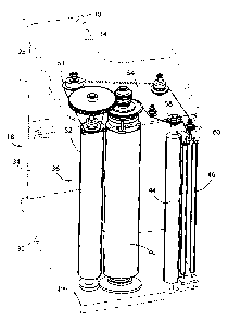
intended
goal of wrapping a load with a stretched web of film. However, the procedure
of
threading the film web through the series of rollers in the film web dispenser
prior to
operation of the stretch wrapping apparatus has been found to be time
consuming and
difficult. This is especially true now because of the development of film web
dispensers
having increased numbers of rollers and also because such rollers are often
closely spaced
and difficult to turn because of their effective interconnection for
prestretching the film
web prior to dispensing the film web on the load.
SUMMARY OF THE INVENTION
[0004) One aspect of the present invention is a film dispenser of a stretch
wrap machine.
The film dispenser includes a stretching device having a support structure and
a film
support for rotatably holding a roll of stretchable film. First and second
rollers are
rotatably mounted to the support structure, each of which defines a first end.
The film
dispenser includes a take-off device for supporting film as it is fed from the
stretching
device. A power drive assembly includes a motor, and the power drive assembly
is
configured to rotate the first and second rollers to stretch a film between
the rollers. The
film dispenser further includes an elongated flexible member forming a loop
and having a
connector adapted for securing stretchable film. A guide assembly adjacent the
first ends
of the first and second rollers movably supports the elongated flexible member
to guide
stretchable film through the film dispenser. The power drive assembly includes
a
disengagable drive that is operably coupled to the elongated flexible member
to provide
powered movement of the elongated flexible member. The drive member is
disengagable
from the motor such that the first and second rollers can be rotated under
power while the
-2-
CA 02457997 2004-02-18
elongated flexible member is disengaged from the motor. The film dispenser may
be
utilized with wrapping machines having a rotatable turntable. Alternately, the
stretching
device may be utilized with wrapping machines of the type having an arm that
rotates the
film dispenser about packages to wrap the film. The elongated flexible member
may
comprise a chain, and the guide assembly may include a plurality of sprockets.
The film
dispenser may include a tensioning device that tensions the chain.
[0005] These and other features, advantages, and objects of the present
invention will be
further understood and appreciated by those skilled in the art by reference to
the following
specification, claims, and appended drawings.
BRIEF DESCRIPTION OF THE DRAWINGS
[0006] Fig. 1 is a perspective view of a wrap machine of the present
invention;
[0007] Fig. 2 is a bottom front perspective view of a carriage of the present
invention
without a motor;
[0008] Fig. 3 is a top front perspective view of the carriage of the present
invention
without the motor;
[0009] Fig. 4 is a top view of the carriage of the present invention without
the motor;
[0010) Fig. 5 is a bottom front perspective view of the carriage of the
present invention
with the motor;
(0011] Fig. 6 is a top front perspective view of the carriage of the present
invention with
the motor;
[0012) Fig. 7 is a top close up perspective view of the carriage of the
present invention
with the motor;
[0013] Fig. 8 is a partially fragmentary top view of the carriage according to
another
aspect of the present invention without the motor;
[0014] Fig. 9 is a fragmentary side view of the carriage of Fig. 8;
[0015] Fig. 10 is a fragmentary, end view of the carriage of Fig. 8; and
[0016] Fig. 11 is an enlarged view of the tensioner of Fig. 10.
DETAILED DESCRIPTION OF PREFERRED EMBODIMENT
[0017] For purposes of description herein, the terms "upper," "lower,"
"right," "left,"
"rear " "front " "vertical " "horizontal " and derivatives thereof shall
relate to the
> > > >
invention as oriented in Fig. 1. However, it is to be understood that the
invention may
assume various alternative orientations and step sequences, except where
expressly
-3-
CA 02457997 2004-02-18
specified to the contrary. It is also to be understood that the specific
devices and
processes illustrated in the attached drawings and described in the following
specification
are simply exemplary embodiments of the inventive concepts defined in the
appended
claims. Hence, specific dimensions and other physical characteristics relating
to the
embodiments disclosed herein are not to be considered as limiting, unless the
claims
expressly state otherwise.
[0018] The reference number 10 (Fig. 1) generally designates a wrap machine of
the
present invention. The wrap machine 10 includes a base 12 having a turntable
14
mounted thereon. The wrap machine 10 further includes a column 16 having a
vertically
movable film dispenser or carriage 18 (Figs. 2-4) located therein. Stretch
wrap 20 moves
with the carriage 18 and exits the column 16 through a vertical slot 22 in the
column 16.
The stretch wrap 20 wraps a package 24 mounted on the turntable 14 and
rotating
therewith. Although not shown, the wrap machine 10 may also include a gripping
and
cutting device for gripping the stretch wrap 20 and cutting the stretch wrap
20 during
certain portions of the process of wrapping the stretch wrap 20 about the
package 24.
Such gripping and cutting devices are well known to those skilled in the art.
[0019] In the illustrated example, the carriage 18 (Figs. 2-7) includes a
source of the
stretch wrap 20 and moves the source of stretch wrap 20 vertically in order to
wrap the
package 24 between a top and a bottom of the package 24. Preferably, the
source of
stretch wrap 20 includes a roll 26 of stretch wrap 20 placed on the carriage
18. The
carriage 18 preferably prestretches the stretch wrap 20 in order to lengthen
the stretch
wrap 20 in a manner known to those skilled in the art. It will be readily
understood that
the wrap machine may include a support arm or the like that supports carriage
18 for
rotation about a stationary package 24. If this configuration is utilized,
wrap machine 10
does not include a turntable 14, but relies instead on movement of carriage 18
to wrap
package 24.
[0020] The carriage 18 includes a housing 28 having a top plate 30, a bottom
plate 32 and
a plurality of struts 34 connected to the top plate 30 and the bottom plate
32, thereby
providing a rigid structure to the carriage 18. The housing 28 can be moved
vertically
within the column 16 by many methods, all of which are well known to those
skilled in
the art. The carriage 18 also includes a source of power connected thereto in
a manner
well known to those skilled in the art.
-4-
CA 02457997 2004-02-18
[0021] The illustrated carriage 18 includes an S-wrap roller system 36 for
prestretching
the stretch wrap 20 coming from the roll 26 of stretch wrap 20. The S-wrap
roller system
36 includes a first roller 38 and a second roller 40 extending between the top
plate 30 and
the bottom plate 32 of the housing 28. The first roller 38 preferably has a 3-
inch diameter
and the second roller 40 preferably has a 4-inch diameter. The S-wrap roller
system 36
includes a motor 70 connected to the second roller 40 by means of a sprocket
72 on an
output shaft 82 of the motor 70, a chain 76 and a sprocket 74 on a lower axle
84 of the
second roller 40. The first roller 38 is linked to the second roller 40 by a
second gear 80
on the upper axle 88 of the first roller 38 and by a first gear 78 on an upper
axle 86 of the
second roller 40. The first gear 78 on the upper axle 86 of the second roller
40 is smaller
than the second gear 80 on the upper axle 88 of the first roller 38.
Accordingly, the first
roller 38 and the second roller 40 rotate at different speeds, with the first
roller 38
rotating slower than the second roller 40. Therefore, as the stretch wrap 20
moves
through the first roller 38 and the second roller 40 of the S-wrap roller
system 36, the
stretch wrap 20 stretches in a manner that is well known to those skilled in
the art.
[0022] In the illustrated example, the stretch wrap 20 on the roll 26 is
delivered through
the carriage 18 and out the vertical slot 22 in the column 16 to wrap the
package 24. The
roll 26 of stretch wrap 20 is positioned on a mandrel 42 within the housing 28
of the
carriage 18. The stretch wrap 20 departs the roll 26 and moves around the
first roller 38
and the second roller 40 of the S-wrap roller system 36, around a third roller
44 and out
between a pair of film take-off rollers 46. The pair of take-off rollers 46
extends out the
column 16 through the vertical slot 22.
[0023] The illustrated carriage 18 includes a film delivery system 48 for
moving a front
end of the stretch wrap 20 through the carriage 18 when a new roll 26 of
stretch wrap 20
is placed on the carriage 18. The film delivery system 48 includes a threading
chain 50
having a pair of film delivery hooks 52 thereon for pulling the front end of
the stretch
wrap 20 through the carriage 18. The threading chain 50 rides on a first
sprocket 52, a
second sprocket 54 aligned with the second roller 40, a third sprocket 56, a
fourth
sprocket 58 aligned with the third roller 44, a fifth sprocket 60 located
between the pair of
take-off rollers 46, a sixth sprocket 62 and a seventh sprocket 63.
[0024] The stretch wrap 20 is fed through the carriage 18 by the film delivery
system 48
when the roll 26 of stretch wrap 20 is empty. Once the roll 26 is empty, a
user of the
-5-
CA 02457997 2004-02-18
wrap machine 10 presses a button (not shown) that tells a control system of
the wrap
machine 10 to move the carriage 18 to a load position. The load position is
preferably a
centrally located height of the column 16. Once the carriage 18 is in the load
position, a
rear door (not shown) of the column 16 is opened to thereby provide access to
the carriage
18. Once the rear door is opened, the mandrel 42 is swung out of a position
between the
top plate 30 and the bottom plate 32 of the housing 28. A link 64 is pivotally
connected to
the bottom plate 32 and includes the mandrel 42 thereon, thereby allowing the
mandrel 42
to be swung out of the carriage 18. The front end of the stretch wrap 20 is
then roped and
placed on the film delivery hook 52 located between the first sprocket 52 and
the seventh
sprocket 63. The mandrel 42 is swung back into position in the carriage 18
once a new
roll 26 of stretch wrap 20 is placed on the mandrel 42 (in phantom in Fig. 4).
At this
point, the film delivery system 48 is ready to move the stretch wrap 20
through the
carriage 18.
[0025] Once the mandrel 42 is swung back on the carriage 18, the rear door is
closed and
the wrap machine 10 is in thread mode. The wrap machine 10 can be placed into
thread
mode automatically when the rear door is closed or the button can be pressed
to place the
wrap machine 10 in thread mode. To begin threading the stretch wrap 20 through
the
carriage 18 using the film delivery system 48, the tension control of the
motor of the S-
wrap roller system 36 is disengaged. However, the motor of the S-wrap roller
system 36
is engaged at a low speed to turn the second roller 40. Simultaneous with the
rotation of
the second roller 40, a clutch 66 at the top of the second roller 40 is
engaged to thereby
rotate the second sprocket 54 of the film delivery system 48 with rotation of
the second
roller 40. The clutch 66 is preferably electromagnetically controlled and
idles on the
second roller 40 when the clutch 66 is not activated. Accordingly, as the
second sprocket
54 is rotated, the threading chain 50 will pull the front end of the stretch
wrap 20 about
the first roller 38, the second roller 40, the third roller 44 and position
the front end of the
stretch wrap 20 under the fifth sprocket 60 and between the pair of take-off
rollers 46.
The front end of the stretch wrap 20 can thereafter be pulled from the
position between
the pair of take-off rollers 46 and attached to the package being wrapped or
placed into
position on grippers of the gripping and cutting device to begin the process
of wrapping
the package 24. The film delivery system 48 preferably includes a sensor 68
for counting
teeth of the third sprocket 56 to determine the position of the film delivery
hook 52
-6-
CA 02457997 2004-02-18
carrying the front end of the stretch wrap 20. The sensor 68 counts the number
of teeth
of the third sprocket 56 and signals the control system to stop the threading
chain 50 after
the number of teeth passing the sensor 68 is equal to the number of teeth
required to pass
the sensor 68 to move the film delivery hook 52 from the load position to a
position
between the pair of take-off rollers 46. The sensor 68 thereby stops the
threading chain
50 when the front end of the stretch wrap 20 is in position to be removed from
the
carriage 18. At this point, the clutch 66 is disengaged and the wrap machine
10 is ready
to be used in a manner known to those skilled in the art. Therefore, the wrap
machine 10
of the current invention provides both a feed for threading the stretch wrap
20 through the
carriage 18 and for prestretching of the stretch wrap 20 using only one motor,
the motor
previously used only for prestretching.
(0026] With further reference to Figs. 8-11, a carriage 18A according to
another aspect of
the present invention is substantially similar to the carriage 18 described in
more detail
above. However, the sprocket 63A of carriage 18A is mounted on a spring
tensioner 70
that tensions the chain 50. A bracket 72 is mounted to a web 74 of housing 28.
A sliding
member 76 is movably retained by the bracket 72, and a shoulder screw 78 and
bushing
80 rotatably mount the pulley 63A to the end 77 of slide member 76. A
compression
spring 82 is retained on the slide member 76 by a retaining ring 84 at the end
85 of slide
member 76. The spring 82 is compressed between the edge 86 of bracket 72 and
ring 84,
and thereby generates a force in the direction of the arrow "A" (Fig. 8). The
spring
tensioner 70 thereby tensions the threading chain 50 to ensure free wheeling
of the
threading chain, and also to ensure constant tension during the threading
process.
[0027] It will be readily understood that the S-wrap roller system 36
described above is
only one o the stretcher configurations that may utilize the threader of the
present
invention. For example, known stretchers may have a W-wrap roller system, with
a
relatively large stretch roller at each lower "point" of the W pattern, and
nip rollers at
each upper end and the center "point" of the W pattern. The two stretch
rollers of W-
wrap systems are driven in the same rotational direction. The two stretch
rollers may be
driven at different rotational rates, and may have different diameters to
stretch the film.
When a W-wrap pattern is utilized, the electromagnetic clutch is operably
connected to
one of the stretch rollers, and sprockets are positioned at the ends of each
roller to guide
the chain and from a W pattern for threading of the film.
_7_
CA 02457997 2004-02-18
[0028] In the foregoing description, it will be readily appreciated by those
skilled in the
art that modifications may be made to the invention without departing from the
concepts
disclosed herein. Such modifications are to be considered as included in the
following
claims, unless these claims by their language expressly state otherwise.
_g_