Sélection de la langue

Search

Sommaire du brevet 2458252 

Énoncé de désistement de responsabilité concernant l'information provenant de tiers

Une partie des informations de ce site Web a été fournie par des sources externes. Le gouvernement du Canada n'assume aucune responsabilité concernant la précision, l'actualité ou la fiabilité des informations fournies par les sources externes. Les utilisateurs qui désirent employer cette information devraient consulter directement la source des informations. Le contenu fourni par les sources externes n'est pas assujetti aux exigences sur les langues officielles, la protection des renseignements personnels et l'accessibilité.

Disponibilité de l'Abrégé et des Revendications

L'apparition de différences dans le texte et l'image des Revendications et de l'Abrégé dépend du moment auquel le document est publié. Les textes des Revendications et de l'Abrégé sont affichés :

  • lorsque la demande peut être examinée par le public;
  • lorsque le brevet est émis (délivrance).
(12) Brevet: (11) CA 2458252
(54) Titre français: ELEMENTS DE MONTAGE DE REFLECTEUR ET METHODE ET PINCE DE MONTAGE DE CE REFLECTEUR DANS UN APPAREIL D'ECLAIRAGE FLUORESCENT
(54) Titre anglais: REFLECTOR MOUNTING ARRANGEMENT AND METHOD AND CLIP FOR MOUNTING A REFLECTOR IN A FLUORESCENT LIGHT FIXTURE
Statut: Périmé et au-delà du délai pour l’annulation
Données bibliographiques
(51) Classification internationale des brevets (CIB):
  • F21V 07/10 (2006.01)
  • F21V 17/10 (2006.01)
(72) Inventeurs :
  • RABY, BRUCE R. (Canada)
  • RABY, FREDRICK R., SR. (Canada)
(73) Titulaires :
  • BRUCE R. RABY
  • FREDRICK R., SR. RABY
(71) Demandeurs :
  • BRUCE R. RABY (Canada)
  • FREDRICK R., SR. RABY (Canada)
(74) Agent: MACRAE & CO.
(74) Co-agent:
(45) Délivré: 2008-02-05
(22) Date de dépôt: 2004-02-17
(41) Mise à la disponibilité du public: 2005-08-17
Requête d'examen: 2004-04-28
Licence disponible: S.O.
Cédé au domaine public: S.O.
(25) Langue des documents déposés: Anglais

Traité de coopération en matière de brevets (PCT): Non

(30) Données de priorité de la demande: S.O.

Abrégés

Abrégé anglais


A reflector mounting for fluorescent light fixtures in which a rectangular
reflector
sheet is formed and held in a trough shape by a series of bracket clips hooked
to side edges
thereof, the bracket clips having a hole receiving the light tube to thereby
hold the reflector in the
light fixture.

Revendications

Note : Les revendications sont présentées dans la langue officielle dans laquelle elles ont été soumises.


THE EMBODIMENTS OF THE INVENTION IN WHICH AN EXCLUSIVE PROPERTY OR
PRIVILEGE IS CLAIMED ARE DEFINED AS FOLLOWS:
1. A reflector arrangement for a fluorescent light fixture of a type including
an elongated
fluorescent tube comprising:
a generally rectangular reflector sheet held in a trough shape by a series of
bracket clips;
said bracket clips each configured as a flat sheet with a rounded contour
perimeter edge
and having a central hole formed therein sized to slidably receive said
fluorescent tube, a slot
substantially narrower than said fluorescent tube extending in from said
perimeter edge of each
bracket clip into said hole to enable fitting of each bracket clip onto said
fluorescent tube at an
intermediate location along the length thereof, each of said bracket clips
further including a pair
of peripheral notches extending into said perimeter edge in opposite
directions and generally
circumferentially with respect to said hole;
said reflector sheet having opposite edges each received into a respective one
of said
bracket clip peripheral notches to hold said reflector sheet in a curved
trough shape extending
partially around said perimeter edge of said bracket; and
said bracket clips thereby holding said reflector on said fluorescent tube and
holding said
reflector sheet in said trough shape partially surrounding said fluorescent
tube and said bracket
clip.
2. The reflector arrangement according to claim 1 wherein said reflector sheet
is constructed
of corrugated plastic having a reflecting film bonded on one side.
7

3. The reflector arrangement according to claim 1 wherein said reflector sheet
has a series
of aligned pairs of notches formed into said side edges, each of said bracket
clip notches received
in a respective aligned pair of said reflector sheet notches.
4. The reflector arrangement according to claim 1 wherein each of said bracket
clips are
constructed from clear plastic.
5. The reflector arrangement according to claim 1 wherein each bracket clip is
formed with
a rounded easily removable at least partially circular knock out portion, said
hole formed therein,
a slot extending around said knock out portion leaving an easily breakable
connecting portion to
remaining portions of said clip to allow a larger hole to easily be formed in
each bracket clip by
breaking said connecting portion and removing said knock out portion, said
larger hole sized to
receive a fluorescent tube of a larger diameter than said hole within said
knock out portion.
6. The reflector arrangement according to claim 1 wherein said slot extending
to said hole
towards said reflector sheet.
7. The reflector arrangement according to claim 1 wherein said slot extending
to said hole
in each bracket clips forms two resiliently bendable portions able to be
twisted apart in opposite
directions to create a gap allowing allow each of said bracket clips to be
installed onto said
fluorescent tube pass through said gap and into said hole without removal of
said fluorescent tube
from said fixture.
8

8. A method of mounting a reflector sheet in a fluorescent light fixture
having a light tube
installed therein without removing said light tube, comprising
forming a plurality of bracket clips each comprised of a flat sheet of plastic
having a hole
lying within a perimeter edge of said clip and an opposing pair of notches
extending into said
perimeter edge of each bracket clip, said notches extending in opposite
directions and generally
parallel to a tangent circumferentially with respect to said hole, so that
said notches are able to
receive and retain a respective side edge of said reflector sheet with said
reflector sheet bent into
a curved trough shape; and
passing the light tube into said central hole formed in each bracket clip
through a
substantially narrower slot also formed therein extending from said perimeter
edge into said hole
by bending apart bendable tab portions defining the respective sides of said
slot extending into
said hole to form a gap larger than the diameter of said tube, and positioning
side edges of said
reflector in a respective one of said notches of each clip to connect the same
thereto, to hold said
reflector on said light tube and in said trough shape extending partially
around said perimeter edge
of each of said clips.
9. A bracket clip for a reflector comprised of a piece of flat sheet material
having a pair of
notches extending in from a perimeter edge thereof for receiving a reflector
sheet, said notches
extending in generally opposite directions away from each other; a hole formed
in said clip
between said notches, said hole sized to receive a fluorescent light tube; and
a slot extending from
said perimeter edge into said hole from said perimeter edge of said bracket
clip at a location
between said pair of notches.
9

10. The bracket clip according to claim 9 wherein said hole is formed in a
removable
knockout portion of an at least partially round shape to allow formation of a
larger size hole by
removal of said knockout portion of said bracket clip around said hole.
11. The bracket clip according to claim 9 wherein said sheet material is clear
plastic.
12. The bracket clip according to claim 9 wherein said perimeter of said
bracket clip is of
rounded flattened shape having a protuberance on either end into which a
respective one of said
pair of notches extends in opposite generally circumferential directions.

Description

Note : Les descriptions sont présentées dans la langue officielle dans laquelle elles ont été soumises.

CA 02458252 2004-02-17
REFLECTOR MOUNTING ARRANGEMENT AND METHOD AND CLIP
2 FOR MOUNTING A REFLECTOR IN A FLUORESCENT LIGHT FTNTURF
3
4
Background of the Invention
6 This invention concerns mounting of reflectors in fluorescent light
rixtures. The
7 ability to improve the efficiency of light fixtures has led to adding
reflectors abovc fluorescent.
8 light tubes to increase the output of light to save electrical power.
9 A typical installation comprises fixing a metal reflector to the fixture
liousing with
fasteners, the reflector positioned above the fluorescent tubes in the fixture
housing. This is a
11 slow, labor intensive process, requiring removal of the light tubes and
working overhead standing
12 on a ladder. For commercial installations such as stores, offices,
factories, etc., involving
13 hundreds of fixtures, the cost is substantial.
14 In U.S. patent 5,613,761 issued to the present inventors a lightweight
reflector
using plastic corrugated material with a foil ftlm facing is described. This
reflector can be
16 inou.nted to the tubes themselves, as described in that patent, using
cutouts in erid pieces of the
17 reflector.
? 8 While that mounting and reflector is a considerable improvement over the
prior
19 reflectors, the reflector m.ust first be formed into a trough shape by
fixing end pieces to the
reflector ends, and installation is still time consuming as the formed
reflector must bc
21 maneuvered properly to secure the same into place on the tubes.
22 In addition, there is a great variety of sizes of tubes and fixtures in
use, aiid it
23 would be advantageous to provide a standardizcd mounting to fit znost or
all such light sizes_
24 It is the object of the present invention to provide a reflector mountiaig
~~~__ _

CA 02458252 2004-02-17
; an-angement and niethod for fluorescent light fixtures which makes it
sirnp(e and quick to install
? a reflector to a variety of light sizes_
3
4 Summary of ttie Invention
The above object and others which will become apparent upon a reading of the
6 following specification and claims are achieved by a using flat rectangular
reflector sheet fitting
7 within the fixture housing, preferably constructed of corrugated plastic
with a reflective film oti
8 one side which is preformed with a series of pairs of aligned notches on
each side edge. A
9 plurality of bracket clips preferably of a generally rounded shape and made
from clear plastic
sheet stock each have a pair of opposing slots extending into each end of the
clip bracket. The
11 slots are spaced and angled to receive a respective reflector side edge
when the reflector is
12 forined into an arcuate trough.
13 The reflector blank has pairs of aligned slots along its length which znay
each is
14 received in a bracket clip slot to securely position the reflector on a
tube, whieli is received in a
central hole in each bracket clip.
16 The bracket clips may come in different sizes and configurations and are
foizneci
17 with a knockout hole to receive different sized light tubes. Inwardly
extending tabs extend
18 partially around the hole and are able to be resiliently bent or twisted to
allow the tube to be
19 pushed into the hole past the tab, the tab moving back over the tube to
prevent the tube from
escaping from the hole.
21 Providing additional slots in the perimeter of the bracket clips allow
different
22 reflector etu-vatures to be set.
2

CA 02458252 2004-02-17
2 Dcscription of the Drawinas
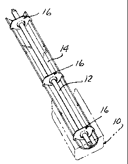
3 Figure 1 is a pictorial view of an inverted reflector held on a fluorescent
light ttlbe
4 with a series of bracket clips which also hold the reflector in a trough
shape, a fragnzentary
portiotl of the light fixture shown in phantom lines.
6 Figure 2 is an enlarged cross sectional view taken through the inverted
reflector of
7 Figure 1 showing one of the bracket clips in fiu-ther detail.
8 Figure 3A-3D show a reflector blank with markings to trinl to allow cuttitig
to
9 various length reflectors as indicated in the various views.
Figure 4 is a pictorial view of another embodirneiZt of a bracket clip of the
11 invention.
12 Figure 5 is a planar view of yet atiother bracket clip according to r.hc
invention
13 formed with two slot pairs.
14 Figure 6 is a planar view of still another embodiment of a bracket clip
according
to the invention formed with pairs of oppositely extending slots.
16
17 Detailed Description
1 s In the following detailed description, certain specific terminology will
be
19 employed for the sake of clarity and a particular embodiment described in
accordance with the
requirements of 35 USC 112, but it is to be understood that the saine is not
intended to be
21 tiiniting and should not be so con.strued inasmuch as the invention is
capable of taking niany
22 forn-is and variations within the scope of the appended claims_
3

CA 02458252 2006-10-10
1 Referring to the drawings, the present invention concerns a fluorescent
light
2 fixture 10 (Figure 1) in which one or more fluorescent light tubes 12 are
mounted. According
3 to the present invention, a reflector 14 is mounted to the fixture 10 by an
arrangement
4 including a series of clip brackets 16 preferably made of a clear plastic
sheet material so as to
be as unobtrusive as possible and to not obstruct light emanating from the
tube 12.
6 Each bracket clips 16 hold the sides edges of the reflector 14 to form the
same
7 in a trough shape and are received on the fluorescent tube 12 to hold the
reflector over the tube
8 12 without any connection to the housing 10.
9 Figure 2 shows further details. The reflector 14 is preferably constructed
generally as described in U.S. Pat. No. 5,613,761, but other reflectors could
be used. A
11 backing of corrugated plastic 18 is slit longitudinally on one side to
allow ready forming into a
12 trough shape by bending along the corrugation lines.
13 A reflective film 20 is bonded onto the other side to provide maximum
14 reflection of light emanating from the fluorescent tube 12 to concentrate
light directed from
the tube in the direction towards the open side of the fixture 10.
16 Each bracket clip 16 is made from flat plastic sheet stock in a rounded
shape
17 having a protuberance 22 at each end. A pair of opposing circumferential
slots 24 are each
18 recessed into the perimeter of a respective protuberance 22 angled slightly
in convergent
19 directions toward each other. The spacing between the two slots 24 is less
than the distance
between the two side edges 26 of reflector 14 when the reflector lies flat so
that the reflector
21 sheet is formed into a trough shape when the side edges 26 are hooked into
a respective slot 24
22 as shown. The reflector 14 has a series of notches 25 cut into its side
edges 26. The bracket
4

CA 02458252 2006-10-10
1 clips 16 are installed with notches 24 receiving the notches 25 to locate
and secure the same.
2 A series of spaced apart bracket clips 16 are installed in this way along
the
3 length of the reflector 14 to form a complete trough shape along its length.
4 A central hole 28 is sized to receive the light tube 12, the hole 28
extending
into a gap 30 provided to create two resiliently bendable tabs 32 extending
partially around
6 said hole. Either of the bendable tabs 32 can be twisted aside to allow the
light tube 12 to be
7 passed into the hole 28 so that the light tube 12 need not be removed from
the fixture 10 to
8 install the reflector 14.
9 A knockout 34 is also formed by arcuate slots 36 and scoring 38 to allow use
with larger diameter fluorescent light tubes.
11 Figures 3A-3D show how a single reflector blank 40 can be employed to form
12 various lengths reflectors.
13 A series of the notches 25 are provided sufficient in number to allow two,
three
14 or four foot reflectors to be constructed while enabling installation of at
least two clip
brackets.
16 A series of imprinted or scored cutting guide lines 42 A, B, C are provided
on
17 either end, as well as a center guide line 42D.
18 Two longer reflectors l0A for four foot strip fixtures can be produced from
the
19 uncut blank 40.
By cutting along guide lines 42A a shorter reflector l OB is formed for four
foot
21 recessed fixtures.
22 By cutting along the next guide lines 42B and 42D, a pair of two foot
reflectors
23 10C are provided, each having two aligned pairs of notches 25 for two
bracket clips 16.
5

CA 02458252 2004-02-17
1 By cutting along guide lines 42C, a three foot reflector 101) is created
with thrce
2 bracket clips 16 used to form and support the same.
3 Thus, a simple inexpensive arrangement and method for increasing the usefiil
4 light output of fluorescent fixtures is provided using the reflector and
bracket clips as described.
which allows quicker and easier retrofitting of light fixtures in the field.
6 Figures 4-6 show additional versions of the bracket clip.
7 In Figure 4, a bracket clip 44 has a protuberance at each which are bent
over to
8 present a tab 46 with an angled entry flange 48 to simplify assembly of the
reflector 14 thereto
9 and improve gripping thereof.
Figure 5 shows a bracket clip 50 having protuberances 52 formed with
11 circumferential slots 54A, 54B extending in from opposite directions, each
aligned with a
12 respective outside edge 56A, 56B. With the reflector 14 held in the slots
54A and against the
1.3 edge 56A, it is spread flatter than when the bracket 50 is flipped and the
reflector 14 is held in
14 slots 54B and against edge 56B. This allows different curvatures of the
reflector 14 to be set for
a particular installation.
16 Figure 6 shows a brar-ket clip 58 with protuberances 60 in which two slots
62A,
17 62B extend in from the same side to also allow different reflector
curvatures to be set. A knock
18 out 64 is also provided in the bracket clip 58.
19
6

Dessin représentatif
Une figure unique qui représente un dessin illustrant l'invention.
États administratifs

2024-08-01 : Dans le cadre de la transition vers les Brevets de nouvelle génération (BNG), la base de données sur les brevets canadiens (BDBC) contient désormais un Historique d'événement plus détaillé, qui reproduit le Journal des événements de notre nouvelle solution interne.

Veuillez noter que les événements débutant par « Inactive : » se réfèrent à des événements qui ne sont plus utilisés dans notre nouvelle solution interne.

Pour une meilleure compréhension de l'état de la demande ou brevet qui figure sur cette page, la rubrique Mise en garde , et les descriptions de Brevet , Historique d'événement , Taxes périodiques et Historique des paiements devraient être consultées.

Historique d'événement

Description Date
Le délai pour l'annulation est expiré 2011-02-17
Lettre envoyée 2010-02-17
Accordé par délivrance 2008-02-05
Inactive : Page couverture publiée 2008-02-04
Inactive : Taxe finale reçue 2007-11-09
Préoctroi 2007-11-09
Un avis d'acceptation est envoyé 2007-05-18
Lettre envoyée 2007-05-18
Un avis d'acceptation est envoyé 2007-05-18
Inactive : Approuvée aux fins d'acceptation (AFA) 2007-04-24
Modification reçue - modification volontaire 2006-10-10
Inactive : Dem. de l'examinateur par.30(2) Règles 2006-04-12
Demande publiée (accessible au public) 2005-08-17
Inactive : Page couverture publiée 2005-08-16
Lettre envoyée 2004-05-21
Inactive : CIB attribuée 2004-05-20
Inactive : CIB en 1re position 2004-05-20
Toutes les exigences pour l'examen - jugée conforme 2004-04-28
Exigences pour une requête d'examen - jugée conforme 2004-04-28
Requête d'examen reçue 2004-04-28
Demande reçue - nationale ordinaire 2004-03-24
Inactive : Certificat de dépôt - Sans RE (Anglais) 2004-03-24
Déclaration du statut de petite entité jugée conforme 2004-02-17

Historique d'abandonnement

Il n'y a pas d'historique d'abandonnement

Taxes périodiques

Le dernier paiement a été reçu le 2007-11-05

Avis : Si le paiement en totalité n'a pas été reçu au plus tard à la date indiquée, une taxe supplémentaire peut être imposée, soit une des taxes suivantes :

  • taxe de rétablissement ;
  • taxe pour paiement en souffrance ; ou
  • taxe additionnelle pour le renversement d'une péremption réputée.

Les taxes sur les brevets sont ajustées au 1er janvier de chaque année. Les montants ci-dessus sont les montants actuels s'ils sont reçus au plus tard le 31 décembre de l'année en cours.
Veuillez vous référer à la page web des taxes sur les brevets de l'OPIC pour voir tous les montants actuels des taxes.

Historique des taxes

Type de taxes Anniversaire Échéance Date payée
Taxe pour le dépôt - petite 2004-02-17
Requête d'examen - petite 2004-04-28
TM (demande, 2e anniv.) - petite 02 2006-02-17 2005-12-16
TM (demande, 3e anniv.) - petite 03 2007-02-19 2006-11-07
TM (demande, 4e anniv.) - petite 04 2008-02-18 2007-11-05
Taxe finale - petite 2007-11-09
TM (brevet, 5e anniv.) - petite 2009-02-17 2009-02-11
Titulaires au dossier

Les titulaires actuels et antérieures au dossier sont affichés en ordre alphabétique.

Titulaires actuels au dossier
BRUCE R. RABY
FREDRICK R., SR. RABY
Titulaires antérieures au dossier
S.O.
Les propriétaires antérieurs qui ne figurent pas dans la liste des « Propriétaires au dossier » apparaîtront dans d'autres documents au dossier.
Documents

Pour visionner les fichiers sélectionnés, entrer le code reCAPTCHA :


Pour visualiser une image, cliquer sur un lien dans la colonne description du document. Pour télécharger l'image (les images), cliquer l'une ou plusieurs cases à cocher dans la première colonne et ensuite cliquer sur le bouton "Télécharger sélection en format PDF (archive Zip)" ou le bouton "Télécharger sélection (en un fichier PDF fusionné)".

Liste des documents de brevet publiés et non publiés sur la BDBC .

Si vous avez des difficultés à accéder au contenu, veuillez communiquer avec le Centre de services à la clientèle au 1-866-997-1936, ou envoyer un courriel au Centre de service à la clientèle de l'OPIC.


Description du
Document 
Date
(aaaa-mm-jj) 
Nombre de pages   Taille de l'image (Ko) 
Description 2004-02-16 6 258
Abrégé 2004-02-16 1 17
Revendications 2004-02-16 4 122
Dessins 2004-02-16 3 70
Dessin représentatif 2005-07-19 1 7
Dessins 2006-10-09 3 70
Revendications 2006-10-09 4 129
Description 2006-10-09 6 245
Dessin représentatif 2008-01-20 1 8
Certificat de dépôt (anglais) 2004-03-23 1 158
Accusé de réception de la requête d'examen 2004-05-20 1 176
Rappel de taxe de maintien due 2005-10-17 1 109
Avis du commissaire - Demande jugée acceptable 2007-05-17 1 165
Avis concernant la taxe de maintien 2010-03-30 1 171
Correspondance 2007-11-08 1 33