Sélection de la langue

Search

Sommaire du brevet 2459650 

Énoncé de désistement de responsabilité concernant l'information provenant de tiers

Une partie des informations de ce site Web a été fournie par des sources externes. Le gouvernement du Canada n'assume aucune responsabilité concernant la précision, l'actualité ou la fiabilité des informations fournies par les sources externes. Les utilisateurs qui désirent employer cette information devraient consulter directement la source des informations. Le contenu fourni par les sources externes n'est pas assujetti aux exigences sur les langues officielles, la protection des renseignements personnels et l'accessibilité.

Disponibilité de l'Abrégé et des Revendications

L'apparition de différences dans le texte et l'image des Revendications et de l'Abrégé dépend du moment auquel le document est publié. Les textes des Revendications et de l'Abrégé sont affichés :

  • lorsque la demande peut être examinée par le public;
  • lorsque le brevet est émis (délivrance).
(12) Brevet: (11) CA 2459650
(54) Titre français: ENSEMBLE DE SUPPORT ET DE PORTE-ARTICLES POUR VEHICULE
(54) Titre anglais: VEHICLE ARTICLE CARRIER AND BRACKET ASSEMBLY
Statut: Périmé et au-delà du délai pour l’annulation
Données bibliographiques
(51) Classification internationale des brevets (CIB):
  • B60R 9/058 (2006.01)
  • B60R 9/045 (2006.01)
  • B60R 9/048 (2006.01)
  • B60R 9/052 (2006.01)
  • F16B 2/18 (2006.01)
(72) Inventeurs :
  • POTTER, DONALD R. (Etats-Unis d'Amérique)
  • AFTANAS, JEFFREY M. (Etats-Unis d'Amérique)
(73) Titulaires :
  • JAC PRODUCTS, INC.
(71) Demandeurs :
  • JAC PRODUCTS, INC. (Etats-Unis d'Amérique)
(74) Agent: SMART & BIGGAR LP
(74) Co-agent:
(45) Délivré: 2006-06-06
(22) Date de dépôt: 2004-03-04
(41) Mise à la disponibilité du public: 2004-09-27
Requête d'examen: 2004-03-04
Licence disponible: S.O.
Cédé au domaine public: S.O.
(25) Langue des documents déposés: Anglais

Traité de coopération en matière de brevets (PCT): Non

(30) Données de priorité de la demande:
Numéro de la demande Pays / territoire Date
10/401,308 (Etats-Unis d'Amérique) 2003-03-27

Abrégés

Abrégé anglais


A vehicle carrier apparatus adapted to be disposed on an outer
body surface of a vehicle for supporting articles. The apparatus includes
support
rails secured to the outer body, a cross bar spanning the support rails, and
bracket assemblies secured to the cross bar. The bracket assemblies are
coupled to the support rails and include a lower locking clamp pivotally
secured
to the housing. The lower locking clamp rotates between an open position and
a
closed position and secures the bracket assembly to the support rail when in
the
closed position. The open position is approximately 180° from the
closed
position. A detail within the housing contacts a first face of the lower
locking
clamp in the open position and a second face of the lower locking clamp in the
closed position, thus preventing the lower locking clamp from rotating more
than
180° between the open and closed positions.

Revendications

Note : Les revendications sont présentées dans la langue officielle dans laquelle elles ont été soumises.


CLAIMS
What is claimed is:
1. A vehicle article carrier apparatus adapted to be disposed on an
outer body surface of a vehicle for supporting articles thereon, said
apparatus
comprising:
a pair of support rails adapted to be secured to said outer body
surface in spaced apart relation to one another;
a cross bar having a length sufficient to substantially span a
distance separating said support rails;
a pair of brackets assemblies secured to opposite ends of said cross
bar, said bracket assemblies adapted to be coupled to a respective one of each
of said support rails to suspend said cross bar member between said support
rails, each of said bracket assemblies including:
a housing having a clamp portion for receiving at least one surface
of one of said support rails;
a lower locking clamp pivotally secured to said housing, said lower
locking clamp operable to rotate between an open position and a closed
position
relative to said support rail, said lower locking clamp applying a force to
said
support rail to secure said bracket assembly to said support rail when
positioned
in said closed position, said open position being at least approximately
90° from
said closed position to permit said bracket assembly to be lifted off of its
respective said support rail;
13

a locking lever assembly secured to said locking clamp for
rotating said lower locking clamp between said open position and said closed
position;
said locking lever assembly further being pivotable between a first
position and a second position and operable to supply a tightening force upon
said lower locking clamp, when said lower locking clamp is in said closed
position, to draw said lower locking clamp toward said clamp portion and to
increase said force applied by said lower locking clamp upon said support rail
when moved from said first position into said second position.
a center through bore that extends through said housing and
receives said lower locking clamp;
a detail located within said center through bore that cooperates with
said lower locking clamp to prevent said lower locking clamp from rotating
past
said open position and past said closed position.
2. The vehicle article carrier apparatus of Claim 1, wherein said lower
locking clamp comprises a planar portion.
3. The vehicle article carrier apparatus of Claim 1, wherein said lower
locking clamp comprises:
a support rail contact portion; and
a boss portion having a first face and a second face.
14

4. The vehicle article carrier apparatus of Claim 3, wherein said first
face contacts a first side of said detail when said lower locking clamp is in
said
closed position and said second face contacts a second side of said detail
when
said lower locking clamp is in said open position.
5. The vehicle article carrier apparatus of Claim 1, wherein said
locking lever assembly comprises a locking lever that is seated in a
horizontal
position within a recessed portion of said housing when not in use.
6. The vehicle article carrier apparatus of Claim 1, wherein said
locking lever further comprises a raised portion to receive one or more
fingers of
an operator to permit movement of said raised portion between a horizontal
position and a vertical position.
7. The vehicle article carrier of Claim 1, wherein said locking lever
assembly comprises a locking lever pivotally secured to said housing that is
movable rotationally about a first axis, and pivotally about a second axis
transverse to said first axis.
8. The vehicle article carrier of Claim 7, wherein said locking lever
includes a camming surface for assisting in effecting an over center locking
action when said locking lever is moved to said second position, to thus hold
said
locking lever in said second position.
15

9. A vehicle article carrier apparatus adapted to be disposed on an
outer body surface of a vehicle for supporting articles thereon, said
apparatus
comprising:
a pair of support rails adapted to be secured to said outer body
surface in spaced apart relation to one another;
a cross bar assembly having an overall length sufficient to span a
distance separating said support rails, for supporting articles thereon;
said cross bar assembly including a pair of bracket assemblies at
opposite ends of said cross bar assembly for engaging said support rails and
supporting said cross bar assembly above said outer body surface, each said
bracket assembly including:
a housing having a clamp portion for contacting at feast one surface
of a respective one of said support rails;
a locking lever assembly operably associated with said housing for
locking said bracket assembly to said respective support rail;
said locking lever assembly having a locking lever and a locking pin
operably coupled to one another;
a locking clamp threadably engaged with a threaded portion of said
locking pin and movable from a first position, wherein said locking clamp is
clear
of said respective support rail allowing said bracket assembly to be removed
from said respective support rail, to a closed position wherein said locking
clamp
is positioned adjacent to said respective support rail in position to be
clamped
thereto;
16

one of said housing and said clamping member including a
structural detail defining a pair of spaced apart first surfaces, and the
other of
said housing and said clamping member including a pair of second surfaces,
wherein said first and second surfaces limit rotational movement of said
locking
clamp to an arc of at least about 90 degrees, one end of said arc defining
said
open position for said clamping member and the other end of said arc defining
a
closed position for said clamping member;
wherein rotational movement of said locking lever assembly causes
rotational movement of said locking clamp from said open position to said
closed
position;
wherein one pair of said first and second surfaces limits movement
of said clamping member beyond said open position, and another pair of said
first and second surfaces limits movement of said clamping member beyond said
closed position; and
wherein said locking lever is operable to be moved from a first, user
accessible position, into a second, storage position on said housing and held
in
said second, storage position.

10. The vehicle article carrier of claim 9, wherein said locking lever is
coupled to said housing to provide an over center locking action when moved
between said first, user accessible position and said second, storage
position.
11. The vehicle article carrier of claim 9, wherein said locking lever
includes a camming surface that cooperates with said housing to provide an
over
center locking action when moved between said first, user accessible position
and said second, storage position.
12. The vehicle article carrier of claim 9, wherein said locking clamp
moves within an approximate 180 degree arc between said open and closed
positions.
13. The vehicle article carrier of claim 9, wherein said clamping member
includes a boss portion, and wherein said boss portion includes one of:
said structural detail; and
said pair of second surfaces.
14. The vehicle article carrier of claim 9, wherein said housing includes
said structural detail, and locking clamp includes said pair of second
surfaces.
18

15. The vehicle article carrier of claim 14, wherein said locking clamp is
moved automatically from said open position to said closed position when said
locking lever is rotated 180 degrees in a first rotational direction.
16. The vehicle article carrier of claim 9, wherein said locking pin is
rotated about an longitudinal axis extending transversely of an axis around
which
said locking lever is moved.
17. The vehicle article carrier of claim 16, wherein said locking lever is
coupled pivotally to said housing, and wherein said housing includes a recess
within which said locking lever resides when said locking lever is placed in
said
second. storage position.

Description

Note : Les descriptions sont présentées dans la langue officielle dans laquelle elles ont été soumises.

CA 02459650 2004-03-04
I~~~~i
j0001] The present invention relates to vehicle article carriers. try~re
particularly, the present invention relates to a vehicle article carrier
having a
bracket assembly with a simplified and improved locking ~°nEChanism.
~~Gta~~l~7fVi.7 F 'f'l-i~ ll~i'VEI~i'~'I(V
j002] ~tehicte article carriers are used in a ~oide variety of applications
for supporting and secui~ing articles of various sizes ;above an outer surface
of a
vehicle. Typically, vehicle article carriers include a pair of support rails
that are
1Q secured t~ the outer body surface of the vehicle. The support rails are
typically
straight and mounted on teas, outer body surface to e;~terad i~arallei to each
~ther.
The support rails are usually secured along a major longitudinal iengtof the
vehicle roof, rear deck lid, or truck bed.
j~03j . Typically, at least ~ne ~ ;roes bar eaten&~s betuveen th~r tyro
support rails. The cross bar is secured to eaci~ support rail by bracket
assemblies that are fastened to each end of the cross bar. Each
b~°acket
assembly typically corr~prises a io~;king rnechanisrn fir relr;asably securing
it to
an associated one of the opposing support rails.
j04~ ~llhile current vehicle article carriers perforrn adequately for their
2 ~ intended ease they are ail subject to irnprovernent., p~;cifically, the
locking
mechanisms of rnany current article carriers typically include a relatively
large
1

CA 02459650 2004-03-04
nc~rnber of complex parts, thus rr~aking the locking rr~echanisrr~s sornewhaf
difficuit and/or costly to assemble. ~an~ such locking rnechanisrns require
one
or rr~ore independent springs to perform the needed locking action, which can
add to the complexity and cost of the lo~~king rnecl~anisrn. Farther, with
sorne
article carriers, the locking rnechanisrns can be difficult to arorr~pletely
disengage
from their respective s~ppc~rt rails when opened, and thereby prevent one or
both
of the bracket assemblies ~rorn being easily repositioned along its associated
support rail or removed from the support rail.
~~005 ~onseq~er~tly; there exists a need for a vehicle article carrier
1o having a cross bar with bracket asserrobiies at each end thereof that
include a
simplified locking rnechar~ism that is easier to asser~~bie, :more cost
efficient to.
produce, and pr~vides excellent reliability in its locking orientation.
~f~f~,F~~~'>i'I~E I~lgi'E°CI~
~0~06] The present invention f~lfi6ls the seeds of the prior art by
2 o bracket asser~nblies are coupled to the support rails and each includes a
lower
locking clamp pivotally secured to a hosing of its respective bracket
asserrabiy.
~ locking le~rer rotates the lower I~cking clarrap between s.n open position
and a
closed position. This secures the bracket assernbiy to tl~e support raiE when
the

CA 02459650 2004-03-04
into the closed position. ~"he structural detail thus prevents the lo~rer
locking
clamp trorn rotating more than ~ 8Qa between the open arid dosed positi~ns.
This
enables the locking t~larrnp to be moved het~rveen~ the ~~all open arid closed
positions orith just rotatiorts:l overr~ent of the locking lever. once the
locking
lever is in its closed position and pre-tigha.ened onto its associated
supp~~rt rail,
3

CA 02459650 2004-03-04
purposes of illustration onay and a.re nct intondect ~o iirnit the scope of
the
invention.
RRI~F ~~SGRI~''~I~fV ~F 1°HE ~Ft~e~ll4~GS
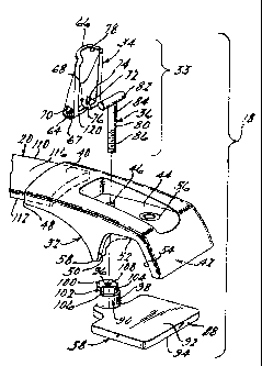
the present invention;
ho ~~~1~~ Figure ~ ie~ a perspective view of a portion of a cress barn a
portion of a support rail, anri a bracket assembly of the apparatus of Figure
1 in a
respective support rails
[ n1 ~ Figr~re is a cross-sectional view taken along section line 5-5 in
Figure 4;
20 [~1] Figure ~ is a side view of the bracket ass~~mbiy of Figure 4. but
with the cocking ciarr~p in thc~ ~t~!!y open position9 and
X001 ~ Figurr~ ~ is a cross-sectional view taken along line section 7-7 in
Figure ~.
4

CA 02459650 2004-03-04
~0 96] 'The follovuing descriptican of the preferred embodiment is merely
exemplary ire nature and is in no ~aay intended to limit the invention, its
application, or uses,
0~11~ F~eferring tea Figure 1, a vehicle article carrier apparatus 1 ~ in
accordance with a preferred errabodirr~ent of the preset i~~ventiori is
!Ilustrated.
'The article carrier apparatus 1 ~ is shown i~7sta!!ed on an exp~mplary motor
vehicle
12. Specifically, the apparatus 1 ~ is shown installed ors a roof portion '!
4. of the
motor ~rehicte 12. VVhiie Figure 1 shorn~s.the apparatus 1~J secured to the
r~of
portion 1 ~, it ~nril9 be appreciated that the apparatus ~ o can just as
readily be
secured at carious other surfaces about era exterior of the rrnotor vehicle
1~.
Further, the apparatus 10 is suitable for use ors virtually ar~y form of
vehicle such
as, taut not limited t~, a sport utility ~ehicie9 station vvaor~, sedan, etc.
X01 ~ 'the apparatus 1 CS generally includes a paii° of elongated
support
rails 1 ~, at least tvvo cross bar bracket assemblies 1 ~~, stud at least one
cross bar
2 o bars.
(~~1 ~~ s4s illustrated in Figure 1, the support rails 16 are pieced in a
ger~era!!y parallel relationship along opposite sides of the roof 14.. 'The
support
5

CA 02459650 2004-03-04
X021 ~'he rte~~ ~~~~t~~r~ 40 6nci~ade~ ~ h~l~~pc~rt~~r~ 4~e The .h~lic~w

<IMG>

CA 02459650 2004-03-04
78 to permit easy actuation of the locking lever ~~ by or~a or rnora fingers
of an
operator.
[0026 The locking pin 0has vertical ~~haf~l portion 80 and a head
portion 82. The shaft portion 80 has a first end 84 and a second end 86. The
second end 86 is threaded to threadly er;gage ~rith the lo~u~er locking clarnp
8.
The head portion 82 is posivior~ed at the first end 84 and is ninety degrees
to the
vertical shaft portion 80 to provide the locking pin ~6 ~~vith a "T" shape.
[002°~The lover locking clar~~p 08 includes a planar support rail
contact portion 88 and a boss surface portion 90~~ °~he support rail
contact
1 a portion 88 has an upper surface 2 and a lover surt~ace 8. The upper
surface
92 is planar to cornplerr~er~t the lower rail surface 2~, which is also
planar. The
boss portion 90 extends frs~o~n the upper surface 92 arid in circular.
ExtEanding
through the enter of the boss por~rion 90 is a threaded through hole 98.
[0~2~. The boss portion 90 includes a lower circular base portion 9~
arid an upper portion ~ 00. The ~spper portion 100 its cs~m~prised of a first
serni~
circular portion 102 and a. second semicircular portion 10~. The first serni-
circular portion 102 has a diameter that is equal to thud k~ase portion 98.
The
second semi-circular portion 104 has a diameter that is less than the first
semi-
circular portion 102, t3ue to the difference in diameters between the first
portion
102 and the second portion 104, a first face ~ 08 and a second face 108 (see
also
Figure 5) of the first semi-circular portion 102 are created.
[0028 9lVith ~f~arth~~r reference t~ Figures 1 through 39 the cross t'ar 20
will now be described in detail. The cross liar 20 generally includes an
el~ngated
8

CA 02459650 2004-03-04
[0~31j ~'he ~erti~~i si~~ft p~rti~~ ~~ of th~~ l~~~ir~g Pin 36 ~~ct~~ds
9

<IMG>

CA 02459650 2004-03-04
(003~j li~ovarrlent of the bracket asserribiy ~ 8 froithe closed position
of Figures 4 and 5 to the open position of ~'ig~ros 6 arid 7 will now be
described
in detail. The Iockirig lever ~3~ is firs3 lifted to its raised pc,si~ior~ as
seen iri l=figure
C. ~'he locking lever 34~ is lifited by the operator ~rh~ preferably engages
the
raised portion ~78 using his~~ier finger to lift the Sever ~~. This rernoves a
portion
(0034 To return ~Phe b~rac~et a~serribly~ ~ 8 to th~~ closed position and
't 1

38 from rotating further, but permits the locking pin 36 to advance further
into the
threaded through hole 96. As the locking pin 36 is advanced further into the
through hole 96, the lower locking clamp 38 is pulled upward towards, and into
contact with, the lower rail surface 24 to thus further tightly clamp the
bracket
assembly 18 to the support rail 16. The locking lever 34 is then turned
downward
so that it is secured in a horizontal position within the recessed portion 44.
The
camming surface 67 and the over center action of the locking lever 34
maintains
the locking lever 34 in the downward position, thus holding it in the locked
position, while providing a small additional degree of clamping force over the
support rail 16.
It will be appreciated however, that the open and closed
positions could be set at less than 180° apart, depending on the width
of the
contact portion 88 and the positioning of the boss portion 90 thereon.
However,
generally at least a 90° range of movement will be required between the
open
and closed positions, with 180° being more preferred to ensure easy
removal of
the bracket assembly 18.
The description of the invention is merely exemplary in nature
and, thus, variations that do not depart from the gist of the invention are
intended
to be within the scope of the invention. Such variations are not to be
regarded as
a departure from the spirit and scope of the invention.
12

Dessin représentatif
Une figure unique qui représente un dessin illustrant l'invention.
États administratifs

2024-08-01 : Dans le cadre de la transition vers les Brevets de nouvelle génération (BNG), la base de données sur les brevets canadiens (BDBC) contient désormais un Historique d'événement plus détaillé, qui reproduit le Journal des événements de notre nouvelle solution interne.

Veuillez noter que les événements débutant par « Inactive : » se réfèrent à des événements qui ne sont plus utilisés dans notre nouvelle solution interne.

Pour une meilleure compréhension de l'état de la demande ou brevet qui figure sur cette page, la rubrique Mise en garde , et les descriptions de Brevet , Historique d'événement , Taxes périodiques et Historique des paiements devraient être consultées.

Historique d'événement

Description Date
Le délai pour l'annulation est expiré 2009-03-04
Lettre envoyée 2008-03-04
Accordé par délivrance 2006-06-06
Inactive : Page couverture publiée 2006-06-05
Inactive : Taxe finale reçue 2006-03-20
Préoctroi 2006-03-20
Inactive : CIB de MCD 2006-03-12
Un avis d'acceptation est envoyé 2005-11-01
Lettre envoyée 2005-11-01
Un avis d'acceptation est envoyé 2005-11-01
Inactive : Approuvée aux fins d'acceptation (AFA) 2005-10-21
Inactive : CIB attribuée 2005-09-21
Inactive : CIB en 1re position 2005-09-21
Demande publiée (accessible au public) 2004-09-27
Inactive : Page couverture publiée 2004-09-26
Inactive : CIB en 1re position 2004-05-19
Inactive : Certificat de dépôt - RE (Anglais) 2004-04-05
Exigences de dépôt - jugé conforme 2004-04-05
Lettre envoyée 2004-04-05
Demande reçue - nationale ordinaire 2004-04-05
Exigences pour une requête d'examen - jugée conforme 2004-03-04
Toutes les exigences pour l'examen - jugée conforme 2004-03-04

Historique d'abandonnement

Il n'y a pas d'historique d'abandonnement

Taxes périodiques

Le dernier paiement a été reçu le 2006-02-09

Avis : Si le paiement en totalité n'a pas été reçu au plus tard à la date indiquée, une taxe supplémentaire peut être imposée, soit une des taxes suivantes :

  • taxe de rétablissement ;
  • taxe pour paiement en souffrance ; ou
  • taxe additionnelle pour le renversement d'une péremption réputée.

Veuillez vous référer à la page web des taxes sur les brevets de l'OPIC pour voir tous les montants actuels des taxes.

Historique des taxes

Type de taxes Anniversaire Échéance Date payée
Enregistrement d'un document 2004-03-04
Taxe pour le dépôt - générale 2004-03-04
Requête d'examen - générale 2004-03-04
TM (demande, 2e anniv.) - générale 02 2006-03-06 2006-02-09
Taxe finale - générale 2006-03-20
TM (brevet, 3e anniv.) - générale 2007-03-05 2007-02-09
Titulaires au dossier

Les titulaires actuels et antérieures au dossier sont affichés en ordre alphabétique.

Titulaires actuels au dossier
JAC PRODUCTS, INC.
Titulaires antérieures au dossier
DONALD R. POTTER
JEFFREY M. AFTANAS
Les propriétaires antérieurs qui ne figurent pas dans la liste des « Propriétaires au dossier » apparaîtront dans d'autres documents au dossier.
Documents

Pour visionner les fichiers sélectionnés, entrer le code reCAPTCHA :


Pour visualiser une image, cliquer sur un lien dans la colonne description du document. Pour télécharger l'image (les images), cliquer l'une ou plusieurs cases à cocher dans la première colonne et ensuite cliquer sur le bouton "Télécharger sélection en format PDF (archive Zip)" ou le bouton "Télécharger sélection (en un fichier PDF fusionné)".

Liste des documents de brevet publiés et non publiés sur la BDBC .

Si vous avez des difficultés à accéder au contenu, veuillez communiquer avec le Centre de services à la clientèle au 1-866-997-1936, ou envoyer un courriel au Centre de service à la clientèle de l'OPIC.


Description du
Document 
Date
(aaaa-mm-jj) 
Nombre de pages   Taille de l'image (Ko) 
Description 2004-03-04 12 973
Abrégé 2004-03-04 1 57
Revendications 2004-03-04 7 398
Dessins 2004-03-04 3 297
Dessin représentatif 2004-07-22 1 24
Page couverture 2004-09-08 1 56
Dessin représentatif 2006-05-18 1 26
Page couverture 2006-05-18 1 57
Accusé de réception de la requête d'examen 2004-04-05 1 176
Courtoisie - Certificat d'enregistrement (document(s) connexe(s)) 2004-04-05 1 105
Certificat de dépôt (anglais) 2004-04-05 1 159
Avis du commissaire - Demande jugée acceptable 2005-11-01 1 161
Rappel de taxe de maintien due 2005-11-07 1 109
Avis concernant la taxe de maintien 2008-04-15 1 172
Taxes 2006-02-09 1 26
Correspondance 2006-03-20 1 24
Taxes 2007-02-09 1 28