Note : Les descriptions sont présentées dans la langue officielle dans laquelle elles ont été soumises.
CA 02459853 2004-03-05
02839 (PCT/JP02/07227)
SPECIFICATION
MANHOLE STRUCTURE, FLEXIBLE WATER SHUT OFF JOINT FOR
MANHOLE STRUCTURE AND METHOD FOR INSTALLING MANHOLE
STRUCTURE
(FIELD OF THE INVENTION]
This invention relates to a structure of a joining portion between a
wall of a manhole wall and a pipe such as a sewerage pipe or the like, and a
flexible cut-off joint for manhole used in such a joining portion, and more
particularly to a flexible cut-off joint for manhole structure used in a
concrete
manhole structure constructed by a pipe jacking method.
[BACKGROUND ART]
There is known a manhole structure constructed by the pipe jacking
method as shown in FIG. 13. In FIG. 13 is shown a vertical cross-sectional
view of the conventional manhole structure constructed by the pipe jacking
method.
In the conventional manhole structure, as shown in FIG. 13, vertical
shafts 42 are first dug in both of start and arrive by the pipe jacking
method, and
then a pipe 43 such as a sewerage pipe or the like is compressed into the
vertical
shaft 42 by a jack while with digging with a transverse boring machine.
In the conventional pipe jacking method, as shown in FIG. 13, a mold
is subsequently built in the vertical shaft 42 laying the pipe 43 such as
sewerage
pipe or the like therein, and concrete is poured into the mold to form a
manhole
wall 44, whereby the manhole structure is constructed.
In case of digging the vertical shaft, a steel pipe is usually used as an
earth retaining wall for rendering the working area into a minimum range.
In the formation of the manhole wall 44, therefore, a casing steel pipe 45
forms
an outer mold. The previously laid pipe 43 is embedded in the concrete of the
manhole wall 44.
[PROBLEMS TO BE SOLVED IN THE INVENTION]
In such a manhole structure 41, however, the joining portion between
the manhole wall 44 and the pipe 43 such as sewerage pipe or the like is rigid
joining, so that the joining portion between the manhole wall 44 and the pipe
43
-1-
CA 02459853 2004-03-05
02839 (PCT/JP02/07227)
is broken due to uneven settlement of ground in earthquakes or the like.
It is an of the invention to prevent the breakage of the joining portion
between the manhole wall and the pipe in the earthquake or the like by
providing
a manhole structure in which the joining between a cast-in-place concrete
manhole wall and a pipe is rendered into flexible joining by a flexible cut-
off
joint for manhole.
It is another object of the invention to prevent the breakage of the
joining portion between the manhole wall and the pipe in the earthquake or the
like by providing a manhole structure in which the joining between the manhole
and the pipe is rendered into flexible joining by a flexible cut-off joint for
manhole structure.
[MEANS FOR SOLOING PROBLEMS]
The invention concerns a manhole structure comprising a manhole
and a pipe joined thereto, in which the pipe is driven and laid in a vertical
shaft,
and a flexible cut-off joint for manhole structure is disposed on an outer
periphery of the pipe, and the flexible cut-off joint for manhole structure
comprises a rigid cylindrical body and a tubular flexible body located in a
space
between the cylindrical body and the pipe and at an inside of the cylindrical
body,
and the tubular flexible body is made of an elastic body absorbing a
displacement
between the cylindrical body and the pipe, and at least a part of the tubular
flexible body is fixed to the cylindrical body and the pipe, respectively, and
the
outer periphery of the cylindrical body is fixed with a filler for manhole
wall.
Also, the invention concerns a flexible cut-off joint for use in such a
manhole
structure and a method for construction of such a manhole structure.
The inventor has prepared and examined various manhole structures
for rendering the joining portion between a cast-in-place concrete manhole
wall
and a pipe such as sewerage pipe or the like into flexible joining.
As a result, the inventor has found that by using a given flexible cut-
off joint for manhole is obtained a manhole structure wherein the joining
portion
between a pipe laid by the pipe jacking method and the cast-in-place concrete
manhole wall is rendered into the flexible joining, and the invention has been
accomplished.
Moreover, the inventor has prepared and examined various manhole
-2-
CA 02459853 2004-03-05
02839 (PCT/JP02/07227)
structures for rendering a joining portion between a ready-made build-up
manhole and a pipe such as sewerage pipe or the like into a flexible joining.
Consequently, the inventor has found that by using a given flexible
cut-off joint for manhole is obtained a manhole structure wherein the joining
portion between a laid by the pipe jacking method and a manhole, and the
invention has been accomplished.
The flexible cut-off joint for manhole according to the invention
comprises a rigid cylindrical body and a tubular flexible body located at the
inside of the cylindrical body, in which the tubular flexible body is made of
an
elastic body.
The tubular flexible body according to the invention connects between
the rigid cylindrical body and the pipe and acts to absorb a displacement
therebetween. The tubular flexible body is formed so as to expand radially in
a
direction from the inside of manhole to the outside thereof, whereby a fixing
portion can be fixed to an outer periphery of the pipe from the inside of the
manhole.
The joint according to the invention is a flexible cut-off joint for
manhole applied on the joining portion between the pipe and the manhole wall
of
the manhole such as a cast-in-place concrete manhole, a build-up manhole or
the
like.
The cylindrical body according to the invention serves as a dam to
ensue a space between the cylindrical body and the pipe when the manhole wall
is formed by pouring a filler for manhole wall such as a concrete or the like
on
the outer periphery of the cylindrical body.
Also, the cylindrical body according to the invention serves as a dam
on a filler for manhole wall between a drilled surface of the manhole wall and
a
flexible cut-off joint for manhole structure to ensue a space between the
cylindrical body and the pipe when the filler for the manhole wall such as
mortar
concrete or the like is poured on the outer periphery of the cylindrical body.
In the invention, the tubular flexible body made of an elastic body is
arranged in the space between the cylindrical body and the pipe. Such a
tubular
flexible body serves to absorb a displacement between the cylindrical body and
the pipe.
-3-
CA 02459853 2004-03-05
02839 (PCT/JP02/07227)
According to the manhole structure of the invention, the manhole wall
is formed on the outer periphery of the cylindrical body and the cylindrical
body
and the pipe are connected through the tubular flexible body made of the
elastic
body, so that even if different load is applied between the manhole and the
pipe
or a relatively different displacement is produced there between to cause a
position displacement by large-scale diastrophism such as earthquake or the
like,
the tubular flexible body can absorb such load and displacement to prevent the
breakage of the joining portion between the manhole wall and the pipe.
Moreover, according to the manhole structure of the invention, the
outer periphery of the cylindrical body is fixed to the manhole wall through
the
filler for manhole wall embedding a space between the manhole wall and the
pipe,
and the cylindrical body and the pipe are connected through the tubular
flexible
body made of the elastic body, so that even if different load is applied
between
the manhole and the pipe or a relatively different displacement is produced
there
between to cause a position displacement by large=scale diastrophism such as
earthquake or the like, the tubular flexible body can absorb such load and
displacement to prevent the breakage of the joining portion between the
manhole
and the pipe.
[BRIEF DESCRIPTION OF THE DRAWINGS]
FIG. 1 is a vertical cross-sectional view of an embodiment of the
manhole structure according to the invention.
FIG. 2 is a vertical cross-sectional view of another embodiment of the
manhole structure according to the invention.
FIG. 3 is a transverse sectional view of the manhole structure of
FIG. 2.
FIG. 4 is a vertical cross-sectional view of the other embodiment of
the manhole structure according to the invention.
FIG. 5 is a perspective view of a flexible cut-off joint for manhole
used in the manhole structure of FIG. 4.
FIG. 6 is a perspective view of another embodiment of the flexible
cut-off joint for manhole structure according to the invention.
FIG. 7 is a vertical cross-sectional view of an embodiment of the
method for constructing the manhole structure of FIG. 4.
-4-
CA 02459853 2004-03-05
02839 (PCT/JP02/07227)
FIG. 8 is a vertical cross-sectional view illustrating a step of an
embodiment of constructing the manhole structure according to the invention.
FIG. 9 is a vertical cross-sectional view illustrating another step of the
embodiment of constructing the manhole structure according to the invention.
FIG. 10 is a vertical cross-sectional view illustrating the other step of
the embodiment of constructing the manhole structure according to the
invention.
FIG. 11 is a vertical cross-sectional view illustrating a further step of
the embodiment of constructing the manhole structure according to the
invention.
FIG. 12 is a vertical cross-sectional view of further embodiment of
the manhole structure according to the invention.
FIG. 13 is a vertical cross-sectional view of the conventional manhole
structure constructed by the pipe jacking method.
FIG. 14 is a front view of the conventional manhole structure as
viewed from the inside of vertical shaft.
FIG. 15 is a vertical cross-sectional view of the conventional embodi-
ment using a flexible cut-off joint.
FIG. 16 is a partially enlarged view of FIG. 15.
[DETAILED DESCRIPTION OF THE INVENTION]
An embodiment of the invention is explained below.
In the manhole structure according to the invention can be used
manholes previously manufactured in a factory or the like such as a ready-made
build-up manhole and the like in addition to cast-in-place concrete manholes.
A drilled hole of the manhole wall surface for connecting to a pipe may be
formed in building site, but is preferable to be formed in a completely
quality
controlled place such as a factory or the like.
The manhole structure according to the invention can be formed by
jointing a cast-in-place concrete manhole wall and a pipe.
The cast-in-place concrete manhole wall according to the invention
can be formed by pouring a filler for manhole wall into a mold in a building
site
such as vertical shaft or the like. Moreover, the pipe according to the
invention
is a pipe connecting such a manhole to another manhole or the like, which
typically includes a sewerage pipe and the like.
In the invention, such a pipe is driven and laid between at least two
-5-
CA 02459853 2004-03-05
02839 (PCT/JP02/07227)
vertical shafts by pipe jacking method, and thereafter a filler for manhole
wall
can be poured into the mold in the vertical shaft to form a manhole wall
around
such a pipe.
Such a filler for manhole wall is used for constructing the cast-in-
place manhole wall or fixing a flexible cut-off joint for manhole structure
onto a
surface of the drilled hole of manhole wall such as a ready-made built-in
manhole or the like, which can use various materials such as concrete, mortar
concrete and the like.
Moreover, in the invention, the pipe is driven and laid between at
least two vertical shafts by the pipe jacking method, and thereafter ready-
made
concrete members are assembled in the vertical shafts, and a flexible cut-off
joint
for manhole structure can be fixed onto a drilled hole surface formed in the
assembled manhole wall with a filler for manhole wall.
The filler for manhole wall poured between the outer periphery of a
cylindrical body according to the invention and the drilled hole surface of
the
assembled manhole wall is not particularly limited and may be various
concretes
such as a mortar concrete and the like. Especially, if a gap between the outer
periphery of the cylindrical body and the drilled hole surface of the manhole
is
narrow, a shrinkage compensating mortar, a resin mortar, an epoxy resin or the
like can be preferably used.
In case of the cast-in-place concrete manhole, the flexible cut-off joint
for manhole structure according to the invention can be mounted on the pipe
laid
by the pipe jacking method prior to the formation of the manhole wall. Such a
flexible cut-off joint for manhole comprises a rigid cylindrical body and a
tubular
flexible body located at an inside of the cylindrical body, in which the
tubular
flexible body is made of an elastic body.
Also, in case of the ready-made built-in concrete manhole, the
flexible cut-off joint for manhole structure according to the invention can be
mounted on the pipe laid by the pipe jacking method after the formation of the
manhole wall. In this case, after the pipe laid by the pipe jacking method is
extended up to the inner surface of the manhole, the flexible cut-off joint
for
manhole structure can be inserted between the drilled hole of the manhole wall
and the extended pipe.
-6-
CA 02459853 2004-03-05
02839 (PCT/JP02/07227)
The tubular flexible body according to the invention is not particularly
limited in the shape unless it is an elastic body absorbing a displacement
between
the cylindrical body and the pipe, and various shapes can be used.
As such a tubular flexible body can be used, for example, a cylindrical
body. The wall of the tubular flexible body may be a polygonal shape such as
quadrilaterals, pentagon, hexagon or the like, a bellows, a spring and the
like as
viewed from a vertical cross-section thereof.
The tubular flexible body can be inserted and arranged between the
rigid cylindrical body and the pipe. The tubular flexible body is existent in
a
space between the cylindrical body and the pipe and is positioned at the
inside of
the cylindrical body. As shown in the figure, the connecting portion is
positioned
in the inside of the cylindrical body in a radial direction and in the inside
of the
both end portions of the cylindrical body in an axial direction. Moreover, in
case of the pipe jacking method, as shown in the figure, the tubular flexible
body
is extended in a direction capable of fixing a holding portion to the pipe
from the
inside of the manhole.
In the invention, at least a part of the tubular flexible body is fixed to
the cylindrical body and the pipe. In this way, a distance between the manhole
wall and the pipe is kept at a constant level, while even if a different
displace-
ment is produced between the manhole wall and the pipe to cause the position
shifting, the tubular flexible body can absorb efficiently the displacement to
prevent the breakage of the joining portion.
In the flexible cut-off joint for manhole according to the invention, it
is preferable that an end of the tubular flexible body is previously press-
fixed to
the inner surface of the cylindrical body through an expansion band.
Also, it is preferable that after the mounting on the pipe at this state,
the other end of the tubular flexible body is tightened and press-fixed to the
outer
periphery of the pipe through a fastening band.
In the invention, the manhole wall can be formed by pouring a filler
for manhole wall such as a concrete or the like into the outer periphery of
the
flexible cut-off joint for manhole mounted on the pipe.
Also, according to the invention, the filler for manhole wall is poured
into the outer periphery of the cylindrical body in the flexible cut-off joint
for
_7_
CA 02459853 2004-03-05
02839 (PCT/JP02/07227)
manhole mounted on the pipe, whereby a gap between the drilled hole surface of
the previously formed manhole wall and the cylindrical body can be filled up.
In the thus obtained manhole structure, the flexible cut-off joint for
manhole is arranged in the joint portion between the manhole wall and the
pipe,
so that the tubular flexible body in the flexible cut-off joint for manhole
render
the joint portion between the manhole wall and the pipe into flexible joining.
The tubular flexible body according to the invention is made of an
elastic body. Such an elastic body is required to have a flexibility capable
of
absorbing the displacement between the manhole wall and the pipe, but may be
made by using various materials without being particularly limited.
Among the materials for the elastic body, rubber is especially
preferable. Because the rubber has an elasticity in the material itself and is
expandable and is suitable for developing a follow-up property against a pipe
displacement.
The cylindrical body according to the invention may be a dam on the
pouring filler for cast-in-place manhole wall, and ensures a space for the
tubular
flexible body between the cylindrical body and the pipe. For this end, the
cylindrical body is preferable to be hardly deformed by a pressure of a
placing
concrete or the like.
In the invention can be used the cylindrical body made of the same
material as the pipe. However, in the conventional manhole structure 41 shown
in FIG. 13, a boundary face between the pipe 43 such as sewerage pipe or the
like
and the manhole wall 44 is easy to form a water channel for water leakage.
FIG. 14 is a front view of the conventional manhole structure as
viewed from the inside of the vertical shaft. As shown in FIGS. 13 and 14, in
the conventional manhole structure 41, the boundary face between the pipe 43
such as sewerage pipe or the like and the manhole wall 44 is easy to form the
water channel for water leakage with an interstice produced in a lower portion
of
the cylindrical body by the dewatering settlement before the hardening of the
concrete, a fine interstice 47 produced by the drying shrinkage of the
concrete
after aging and the like.
Therefore, when a short length pipe made of the same material as the
pipe is used in the cylindrical body according to the invention, there can be
used
_g_
CA 02459853 2004-03-05
02839 (PCT/JP02/07227)
a sanded short length pipe in which sand are pasted onto an outer peripheral
face
of the pipe for improving the adhesion of the filler for manhole wall to a
face of
the cylindrical body contacting with the filler for manhole wall made of
concrete
or the like.
In the cylindrical body according to the invention, an adhesive
materials or self-adhering material adhering to the filler for manhole wall
made
of concrete or the like can be attached to a face of the cylindrical body
contacting
with the filler for manhole wall constituting the manhole wall.
As such an adhesive material or self-adhering material can be used a
water-expansible rubber based adhesive material or non-curing butyl rubber
based self-adhering material.
Moreover, the non-curing butyl rubber based self-adhering material is
preferable as the adhesive material or self-adhering material. The water-
expansible rubber based adhesive material is expanded by absorbing an incoming
water to stop water through the expansion pressure. While, the butyl rubber
based self-adhering material adheres chemically to the filler for manhole wall
in
the course of curing the filler for manhole wall and is high in the water-stop
ability.
The adhesive material or self-adhering material can prevent the
occurrence of water leakage from the interstice produced in the lower portion
of
the cylindrical body by the dewatering settlement before the hardening of the
filler for manhole wall, the fine interstice produced by the dry shrinkage of
the
filler for manhole wall after aging and the like.
A flange can be arranged on the outer periphery of the cylindrical
body according to the invention. This flange serves to fix the cylindrical
body
to the concrete or the like of the manhole wall by digging into the filler for
manhole wall, and can enhance the adhesion property between the cylindrical
body and the filler for manhole wall.
The material or the like for the flange is not particularly limited
unless it digs into the filler for manhole wall in the manhole wall and is
fixed to
the filler for manhole wall. It is preferable that the flange is hardly
deformed by
a pressure of a placing filler for manhole wall.
Also, an adhesive materials or self-adhering material adhering to the
-9-
CA 02459853 2004-03-05
02839 (PCT/JP02/07227)
filler for manhole wall made of concrete or the like can be attached to a face
of
the flange according to the invention contacting with the filler for manhole
wall
in the manhole wall likewise the aforementioned face of the cylindrical body
contacting with the filler for manhole wall.
As the adhesive material or self-adhering material can be used the
aforementioned water expansible rubber based adhesive material or non-curing
butyl rubber based self-adhering material, and the non-curing butyl rubber
based
self-adhering material is preferable.
According to the flexible cut-off joint for manhole comprising the
cylindrical body provided with the above flange and the adhesive material or
self-adhering material applied to the outer face thereof, the flange attached
with
the adhesive material or self-adhering material on the outer periphery of the
cylindrical body is embedded in the filler for manhole wall in the manhole
wall,
whereby an incoming water between the manhole wall and the cylindrical body
can be blocked and the water leakage from the boundary face to the filler for
manhole wall can be completely prevented.
Moreover, as a flexible cut-off joint for manhole is known one
described in JP-A-9-32020. FIG. 15 is a vertical cross-sectional view of an
example using such a flexible cut-off joint. In this flexible cut-off joint
301, an
end 301a of a rubber flexible joint 301 is press-fixed to a drilled hole face
302a
of a manhole 302 with an expansion band 303 to cover an outer periphery of a
sewerage pipe 304. The other end part 301b of the rubber flexible joint 301 is
tightened with a fastening band 305 and press-fixed to a pipe 304, whereby the
joining portion between the manhole 302 and the sewerage pipe 304 is rendered
into a flexible structure but also the water-stop ability is ensured.
Such a flexible cut-off joint for manhole should be fitted to the
manhole prior to the joining of the pipe.
When the manhole is manufactured in a factory, a hole to be inserted
with a pipe such as sewerage pipe or the like is formed in a specified
position of
the manhole by means of a concrete drilling machine. Although the rubber
flexible portion is press-fixed to the drilled hole face with the expansion
band,
the drilled hole face is not necessarily flat and smooth.
A diamond is embedded in a blade edge of the concrete drilling
-10-
CA 02459853 2004-03-05
02839 (PCT/JP02/07227)
machine, which cuts both of mortar and aggregate. However, an irregularity of
about 2-3 mm is produced by the vibration of the drilling machine, and
especially,
the irregularity becomes larger as the cutting speed is increased. Also, some
bubbles are included in the concrete itself, which may also cause the
irregularity.
As shown in FIG. 16, which is a partially enlarged view of FIG. 15, such an
irregularity of the drilled hole face is easy to cause the water leakage
between the
drilled hole face 302a and the end 301a of the flexible joint 301.
Therefore, the rubber flexible portion should be a rubber having a
certain hardness and being not creped because it is press-fixed to the drilled
hole
face of the manhole with the expansion band to stop water and is required to
absorb a displacement while outstanding water pressure.
However, such a rubber material may cause the water leakage because
it can not follow the irregularity of the drilled hole face in the manhole
only by
the expansive force of the expansion band.
Also, as the drilling number increases, the blade edge wears and
hence the size of the drilled hole decreases by 2-3 mm. As a result, the
pressing
can not be attained with the given expansion band.
In order to solve the above-mentioned defects, it is required to attach
the flexible cut-off joint in a manhole manufacturing factory having a
definite
quality control.
However, when the built-in manhole is used in the pipe jacking
method (the manhole is previously fabricated in the factory and transferred in
a
building site), the conventional technique can not respond to the circumstance
because the flexible cut-off joint is inserted between the drilled hole of the
manhole and the sewerage pipe after the setting of the manhole and the joining
with the pipe in the building site.
In the invention, the flexible cut-off joint for manhole structure is
fitted between the pipe and the rigid cylindrical body, so that the
irregularity of
the drilled hole face is not insignificant because the rubber flexible portion
in the
flexible cut-off joint for manhole structure does not directly contact with
the
drilled hole face of the manhole.
Moreover, in the invention, the above-mentioned adhesive material or
self-adhering material adhering to the aforementioned filler for manhole wall
can
-11-
CA 02459853 2004-03-05
02839 (PCT/JP02/07227)
be attached or a water-expansible polymer resin can be disposed between the
drilled hole face of the build-up manhole and the rigid cylindrical body.
In the invention, it is preferable that the rigid cylindrical body has a
strip-shaped protrusion portion protruding toward a side of the manhole wall.
Such a protrusion portion is advantageous to position the end portion of the
filler
for manhole wall to be poured into the outer periphery of the cylindrical
body.
Also, the protrusion portion can prevent from overbriming of the filler
for manhole wall to the outside of the manhole but also can thicken the filler
for
manhole wall contacting with the cylindrical body, so that the adhesion
property
between the cylindrical body and the manhole wall can be improved.
Such a protrusion portion can be made from the various materials in
various shapes. Preferably, the protrusion portion is made of the same
material
as the cylindrical body, and is comprised from the material and the shape
outstanding the poured filler for manhole wall likewise the cylindrical body.
The expansion band and the fastening band according to the invention
may be made from a polymer material having an appropriate rigidity unless they
can sufficiently press-fix the tubular flexible body to the cylindrical body
and the
pipe to conduct a sufficient water-stop between them.
Each of the flange, the cylindrical body, the expansion band and the
fastening band according to the invention is desirably made of steel,
particularly
stainless steel having an excellent corrosion resistance.
The invention is described in detail with reference to the drawings.
FIG. 1 is a vertical cross-sectional view of an embodiment of the
manhole structure according to the invention. FIG. 2 is a vertical cross-
sectional view of another embodiment of the manhole structure according to the
invention. FIG. 3 is a transverse sectional view of the manhole structure of
FIG. 2. FIG. 4 is a vertical cross-sectional view of the other embodiment of
the
manhole structure according to the invention. FIG. 5 is a perspective view of
a
flexible cut-off joint for manhole used in the manhole structure of FIG. 4.
FIG. 6
is a perspective view of another embodiment of the flexible cut-off joint for
manhole structure according to this invention. FIG. 7 is a vertical cross-
sectional
view illustrating an embodiment of constructing the manhole structure of FIG.
4.
FIGS. 8-11 are vertical cross-sectional views illustrating an embodiment of
-12-
CA 02459853 2004-03-05
02839 (PCT/JP02/07227)
constructing the manhole structure according to the invention every step,
respec-
tively. FIG. 12 is a vertical cross-sectional view of a further embodiment of
the
manhole structure according to the invention.
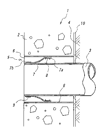
As shown in FIG. 1, a manhole structure 1 as one embodiment of the
invention is formed by joining a manhole wall 2 of cast-in-place concrete to a
pipe 3.
In the manhole structure 1, the pipe 3 is laid within a vertical shaft 4
by a pipe jacking method, and a flexible cut-off joint 5 for manhole is
arranged
on an outer periphery of the pipe 3.
The flexible cut-off joint 5 for manhole comprises a rigid cylindrical
body 6 and a tubular flexible body 7 located at an inside of the cylindrical
body 6,
in which the tubular flexible body 7 is made of an elastic body. The tubular
flexible body 7 is typically made of rubber, and has a tubular shape and
surrounds
the periphery of the pipe 3.
An end 7a of the tubular flexible body 7 is press-fixed to an inner
surface of the cylindrical body 6 with an expansion band 8, and the other end
7b
of the tubular flexible body 7 is fixed to an outer periphery of the pipe 3 by
tightening with a fastening band 9.
The expansion band 8 radially expands its periphery to push the end
7a of the tubular flexible body 7 onto the inside of the cylindrical body 6.
On the other hand, the fastening band 9 fixes the other end 7b of the tubular
flexible body 7 on the pipe 3 by tightening from an outside.
Both the fixing of the end 7a of the tubular flexible body 7 to the
inside of the cylindrical body 6 and the fixing of the other end 7b of the
tubular
flexible body 7 to the pipe 3 can be conducted by selecting a proper adhesive
material and using the bands with such an adhesive material.
The manhole wall 2 is formed by pouring a concrete on an outer
periphery of the cylindrical body 6. Moreover, a soil retaining wall of the
vertical shaft 4 forms a minimum workable area of concrete placing, so that a
casing steel pipe 10 becomes an outer mold.
As mentioned above, in the manhole structure 1 of FIG. 1, when the
concrete for the manhole wall 2 is placed after the fitting of the flexible
cut-off
joint S for manhole to the pipe 3, the cylindrical body 6 forms a dam for the
-13-
CA 02459853 2004-03-05
02839 (PCT/JP02/07227)
concrete of the manhole wall 2, and a space is ensured between the cylindrical
body 6 and the pipe 3 and the tubular flexible body 7 made of the elastic body
connects the cylindrical body 6 to the pipe 3 in such a space.
The tubular flexible body 7 in the manhole structure 1 absorbs an
expansion-contraction displacement, a bending displacement, a shearing
displacement and the like between the manhole wall 2 and the pipe 3 without
applying a load to the pipe 3.
Moreover, an adhesive material or a self-adhering material adhering
to the concrete can be attached to a surface of the cylindrical body 6
contacting
with the concrete of the manhole wall 2 though it is not shown in the figure.
FIG. 2 is a vertical cross-sectional view of a manhole structure 101 as
another embodiment at a state of filling a mortar concrete 105 between a
drilled
hole surface 103a of a wall 103 of a built-in manhole 102 and a flexible cut-
off
joint 104 for manhole structure, and FIG. 3 is a transverse sectional view
thereof.
By connecting a cylindrical body 106 to a sewerage pipe 107 through
a tubular flexible body 108 are ensured spaces 109a,109b between the
cylindrical
body 106 and the sewerage pipe 107, whereby an expansion-contraction displace-
ment, a bending displacement, a shearing displacement and the like of the
sewerage pipe can be absorbed without applying a load to the sewerage pipe
107.
The tubular flexible body 108 is fixed to the inside of the cylindrical
body 106 with an expansion band 110. The expansion band 110 radially
expands its periphery to push an end 108a of the tubular flexible body 108
made
of rubber onto the inside of the cylindrical body 106. The fixation of the
flexible body 108 onto the inside of the cylindrical body 106 may be conducted
by selecting and using a proper adhesive.
Moreover, the other end 108b of the rubber tubular flexible body 108
as a pipe side attaching portion is fixed by tightening the pipe side
attaching
portion from its outside with a fastening band 111. Also, the cylindrical body
106 and the pipe side attaching portion can be fixed by using the band 111 and
an
adhesive together.
The rubber tubular flexible body 108 is cylindrical and surrounds the
pipe 107 from the outside. Although the cylindrical body 106 should be tightly
fixed on the manhole 102 by filling the mortar concrete 105, the operation of
- 14-
CA 02459853 2004-03-05
02839 (PCT/JP02/07227)
filling the mortar concrete can be conducted only from the inside of the
manhole
102.
A protrusion portion 112 serves to prevent the overbriming of the
mortal concrete 105 filled from the inside of the manhole 102 toward the
outside
of the manhole.
Moreover, the filled mortal concrete 105 is contracted by drying with
the lapse of time to form a fine interstice in a boundary face to the drilled
hole
103a of the manhole 102 or to the outer peripheral face of the cylindrical
body
106, which is easy to cause water leakage.
For this end, water expansible polymer resins 113, 114 and the like
are disposed on the drilled hole surface 103a of the manhole 102 or the outer
peripheral face of the cylindrical body 106 to conduct the water-stop through
a
plane pressure of the water expansible polymer resin expanded with water
penetrated from the fine interstice.
FIG. 4 shows a manhole structure 11 as the other embodiment of the
invention. In the manhole structure 11, a flexible cut-off joint 15 for
manhole
as shown in detail in FIG. 5 is used instead of the flexible cut-off joint 5
for
manhole in the manhole structure 1 of FIG. 1.
The flexible cut-off joint 15 for manhole comprises a rigid cylindrical
body 16 and a tubular flexible body 17 located at the inside of the
cylindrical
body 16, in which the tubular flexible body 17 is made of an elastic body
likewise the flexible cut-off joint 5 for manhole.
Also, the manhole structure 11 of FIG. 4 is the same as the manhole
structure 1 in a point that an end 17a of the tubular flexible body 17 is
press-fixed
to an inner surface of the cylindrical body 16 with an expansion band 18, and
the
other end 17b of the tubular flexible body 17 is press-fixed to an outer
periphery
of a pipe 13 by tightening with a fastening band 19, and a manhole wall 12 is
formed by pouring a concrete into an inside of a vertical shaft 14 on an outer
periphery of the cylindrical body 16 with a casing steel pipe 20 as an outer
mold.
In the manhole structure 11, however, a flange 16a is provided on the
outer periphery of the cylindrical body 16 in the flexible cut-off joint 15
for
manhole. The manhole structure 11 of FIG. 4 is different from the manhole
structure 1 of FIG. 1 in this point. The flange 16a bites into the concrete of
the
-15-
CA 02459853 2004-03-05
02839 (PCT/JP02/07227)
manhole wall 12 and serves to fix the cylindrical body 16 to the concrete of
the
manhole wall 12 and enhances the adhesion property between the cylindrical
body 16 and the concrete of the manhole wall 12.
Moreover, in the manhole structure 11, a non-curing butyl rubber
based self-adhering material 16b adhering to the concrete is attached to a
face of
the flange 16a contacting with the concrete of the manhole wall 12.
In the manhole structure 11 of FIG. 4, when the concrete for manhole
wall is placed after the flexible cut-off joint 15 for manhole is fitted onto
the pipe
13, the tubular flexible body 17 absorbs an expansion-contraction
displacement, a
bending displacement, a shearing displacement and the like between the manhole
wall 12 and the pipe 13 without applying a load to the pipe 13 likewise the
manhole structure 1 of FIG. 1.
A boundary face between the concrete of the manhole wall 12 and the
cylindrical body 16 easily forms a water channel, and if the materials of
these are
different from each other, the boundary face more easily a water channel. In
the
cylindrical body 16 of FIG. 4, however, the flange 16a is provided and the non-
curing butyl rubber based self-adhering material 16b adhering to the concrete
is
attached to the face of the flange 16a contacting with the concrete of the
manhole
wall 12, so that the water leakage from the boundary face between them can be
surely prevented.
A flexible cut-off joint 104 for a manhole structure of FIG. 6 is used
in the manhole structure 101. The flexible cut-off joint 104 for manhole
structure has a protrusion portion 112, which is mainly different from the
flexible
cut-off joint 15 for manhole. The flexible cut-off joint 104 for manhole
structure
is used in the build-up manhole 102 of FIGS. 2 and 3 and can be also used in
the
cast-in-place manhole as shown in FIG. 1.
FIG. 7 is a cross-sectional view illustrating a step in the construction
of the manhole structure of FIG. 4. After the pipe 13 such as sewerage pipe or
the like is laid in the vertical shafts 14 by the pipe jacking method, the
flexible
cut-off joint 15 for manhole according to the invention is mounted on the pipe
13
such as sewerage pipe or the like.
After flexible cut-off joint 15 for manhole comprising the cylindrical
body 16 and the tubular flexible body 17 made of the elastic body, wherein the
-16-
CA 02459853 2004-03-05
02839 (PCT/JP02/07227)
one end 17a of the tubular flexible body 17 is previously connected by
expanding
with the expansion band 18, is mounted on the pipe 13, the other end 17b of
the
tubular flexible body is tightened on the outer periphery of the pipe 13 by
the
fastening band 19 to press-fix thereto.
In the invention, as shown in FIGS. 8-11, the build-up manhole 102
and the pipe 107 and the flexible joint 104 for manhole structure can be
jointed
to construct the manhole structure 101 shown in FIGS. 2 and 3.
FIG. 8 is a vertical cross-sectional view showing a state of laying the
sewerage pipe 107 between the vertical shafts by the pipe jacking method, and
FIG. 9 shows a state of suspending down and setting the manhole 102.
FIG. 10 shows a state of extending the sewerage pipe 122 to the inner
surface of the manhole 102 with a socket 121. In the case of the pipe jacking
method, the flexible cut-off joint 104 can be fitted at this state.
FIG. 11 shows a state immediately before inserting and setting the
flexible cut-off joint 104 to the drilled hole surface 103a of the manhole
102.
The manhole structure shown in FIGS. 2 and 3 can be obtained by setting the
joint and filling a mortar concrete between the cylindrical body and the
drilled
hole surface of the manhole.
In the invention can also be obtained a manhole structure as shown in
FIG. 12. In the manhole structure 21 shown in FIG. 12 is used a flexible cut-
off
joint 25 for manhole.
The manhole structure 21 is the same as the manhole structures of
FIGS. 1 and 4 except for the flexible cut-off joint 25 though the concrete
wall is
omitted.
The flexible cut-off joint 25 for manhole comprises a rigid cylindrical
body 26 and a tubular flexible body 27 located at the inside of the
cylindrical
body 26, in which the tubular flexible body 27 is made of an elastic body. It
is
the same as the flexible cut-off joint 15 for manhole in a point that a flange
26a
and a non-curing butyl rubber based self-adhering material 26b are provided on
the outer periphery of the cylindrical body 26.
Also, the manhole structure 21 of FIG. 5 is the same as the manhole
structure 11 in a point that an end 27a of the tubular flexible body 27 is
press-
fixed to the inner surface of the cylindrical body 26 with an expansion band
28,
-17-
CA 02459853 2004-03-05
02839 (PCT/JP02/07227)
the other end 27b of the tubular flexible body 27 is press-fixed to the outer
periphery of the pipe 23 with a fastening band 29 and the manhole wall is
formed
by pouring a concrete in the vertical shaft 24 on the outer periphery of the
cylindrical body 26 with a casing steel pipe 30 as an outer mold.
However, the manhole structure 21 is different from the manhole
structure 11 of FIG. 4 in a point that an end 27a of the tubular flexible body
27
used in the flexible cut-off joint 25 for manhole is protruded in a direction
opposite to the casing steel pipe 30 to form a turnback structure and the end
27a
is fitted onto the cylindrical body 26. This structure is advantageous because
the shape makes it easier to further absorb the displacement between the
manhole
wall and the pipe.
[EFFECT OF THE INVENTION]
According to the manhole structure of the invention, the manhole wall
is formed on the outer periphery of the cylindrical body and the cylindrical
body
and the pipe are connected to each other through the tubular flexible body
made
of the elastic body, so that even if different loads are applied or a
difference of
relative displacement is produced to cause position shifting between the
manhole
wall and the pipe by a large-scale diastrophism such as earthquakes or the
like,
the tubular flexible body can absorb the load and displacement to prevent the
breakage of the joining portion between the manhole wail and the pipe.
According to the manhole structure of the invention, after the laying
of the pipe is completed by the pipe jacking method, the flexible cut-off
joint 15
for manhole is mounted on the pipe and the manhole wall concrete is
constructed,
whereby the joining portion between the pipe and the manhole wall can be
simply made flexible with an excellent working property and. also the water-
stop
ability of the joining portion can be improved.
Moreover, the displacement load applied to the cylindrical body is
effectively absorbed by locating the tubular flexible body of the flexible cut-
off
joint at the inside of the cylindrical body in a space between the cylindrical
body
and the pipe, and also it is prevented to obstruct the flexibility of the
tubular
flexible body by adhesion and solidification of concrete filled in the
construction,
and further it can be prevented that the tubular flexible body is deteriorated
by
always contacting with earth and sand in the underground manhole structure.
-18-