Sélection de la langue

Search

Sommaire du brevet 2459872 

Énoncé de désistement de responsabilité concernant l'information provenant de tiers

Une partie des informations de ce site Web a été fournie par des sources externes. Le gouvernement du Canada n'assume aucune responsabilité concernant la précision, l'actualité ou la fiabilité des informations fournies par les sources externes. Les utilisateurs qui désirent employer cette information devraient consulter directement la source des informations. Le contenu fourni par les sources externes n'est pas assujetti aux exigences sur les langues officielles, la protection des renseignements personnels et l'accessibilité.

Disponibilité de l'Abrégé et des Revendications

L'apparition de différences dans le texte et l'image des Revendications et de l'Abrégé dépend du moment auquel le document est publié. Les textes des Revendications et de l'Abrégé sont affichés :

  • lorsque la demande peut être examinée par le public;
  • lorsque le brevet est émis (délivrance).
(12) Brevet: (11) CA 2459872
(54) Titre français: SYSTEME DE SEPARATION HUILE/EAU
(54) Titre anglais: OIL/WATER SEPARATION SYSTEM
Statut: Périmé et au-delà du délai pour l’annulation
Données bibliographiques
(51) Classification internationale des brevets (CIB):
  • B01D 17/04 (2006.01)
  • B01D 01/14 (2006.01)
  • B01D 01/26 (2006.01)
  • B01D 03/10 (2006.01)
  • B01D 17/02 (2006.01)
  • C02F 01/04 (2006.01)
  • C02F 01/28 (2006.01)
  • C02F 01/32 (2006.01)
  • C02F 01/40 (2006.01)
(72) Inventeurs :
  • LILLEYSTONE, RICHARD (Royaume-Uni)
(73) Titulaires :
  • INDUSTRIAL WASTE TREATMENT LIMITED
(71) Demandeurs :
  • INDUSTRIAL WASTE TREATMENT LIMITED (Royaume-Uni)
(74) Agent: CASSAN MACLEAN
(74) Co-agent:
(45) Délivré: 2010-11-02
(86) Date de dépôt PCT: 2002-09-06
(87) Mise à la disponibilité du public: 2003-03-20
Requête d'examen: 2007-09-04
Licence disponible: S.O.
Cédé au domaine public: S.O.
(25) Langue des documents déposés: Anglais

Traité de coopération en matière de brevets (PCT): Oui
(86) Numéro de la demande PCT: PCT/GB2002/004074
(87) Numéro de publication internationale PCT: GB2002004074
(85) Entrée nationale: 2004-03-05

(30) Données de priorité de la demande:
Numéro de la demande Pays / territoire Date
01307604.7 (Office Européen des Brevets (OEB)) 2001-09-07

Abrégés

Abrégé français

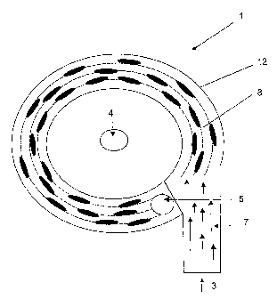
L'invention concerne un évaporateur (1) destiné au traitement de déchets industriels et comprenant un passage incurvé (8) défini par un boîtier (12), un orifice d'entrée (3) par lequel un fluide résiduaire (7) entre dans l'évaporateur (1), un drain (4) situé sous le passage (8) et traversé par un condensat en cours d'utilisation, ainsi qu'une sortie (5) permettant l'extraction du fluide évaporé. L'évaporateur (1) comprend une série d'ailettes (6) présentant une section transversale à profil aérodynamique allongé dans le sens d'écoulement souhaité autour du passage (8), et se prolongeant le long dudit passage (8).


Abrégé anglais


An evaporator (1) for use in industrial waste treatment comprising: a curved
pathway (8) bounded by a casing (12); an inlet port (3) through which waste
fluid (7) enters the evaporator (1); a drain (4) beneath the pathway (8)
through which a condensate passes, in use; and an outlet (5) through which to
draw evaporated fluid. The evaporator (1) has a series of fins (6) of elongate
aerofoil cross-section in the intended flow direction around the pathway (8)
and, extending across the pathway (8).

Revendications

Note : Les revendications sont présentées dans la langue officielle dans laquelle elles ont été soumises.


WHAT IS CLAIMED IS:
1. An evaporator(1) for use in industrial waste water treatment, comprising
a curved pathway (8) bounded by a casing (12);
an inlet port (3) through the casing and through which waste fluid (7) enters
the evaporator (1) in use;
a drain (4) beneath the pathway (8) through which a condensate passes, in
use;
an outlet (5) through the casing and through which evaporated fluid is drawn
in use; and
a series of fins (6) of elongate aerofoil cross-section in the intended
flow direction around the pathway (8) and extending across the pathway (8).
2. An evaporator (1) according to claim 1, wherein the pathway (8) is
substantially horizontal.
3. An evaporator (1) according to either claim 1 or claim 2, wherein the fins
(6)
are substantially vertical.
4. An evaporator (1) according to any one of claims 1 to 3 , wherein the fins
(6)
are arranged parallelto the tangent of the curve of the casing (12).
5. An evaporator (1) according to any one of claims 1 to 4, wherein the inlet
port
(3) of each evaporator is tangential to the pathway (8).
6. An evaporator (1) according to any one of claims 1 to 5, wherein the inlet
port
(3) of each evaporator includes a narrowed throat portion.
7. An evaporator (1) according to any one of claims 1 to 6, wherein the drain
(4)
of each evaporator is conical.
8. An evaporator (1) according to any one of claims 1 to 7, wherein the casing
(12) of each evaporator is formed of a hydrophilic material.

9. An evaporator (1) according to any one of claims 1 to 8, wherein the casing
(12) of each evaporator is metal.
10. An evaporator (1) according to any one of claims 1 to 9, wherein the curve
of
the pathway (8) of each evaporator traces one complete turn of a spiral.
11. An evaporator (1) according to any one of claims 1 to 10, wherein the fins
(6)
of each evaporator have grooves to aid the condensate flow.
12. A low pressure industrial waste water treatment plant comprising
a plurality of low pressure vacuum evaporators (1) according to any of
claims 1 to 11, and
a plurality of heat exchangers and condensers (30) to which fluid is fed
from the outlets (5) of the evaporators (1).
6

Description

Note : Les descriptions sont présentées dans la langue officielle dans laquelle elles ont été soumises.


CA 02459872 2004-03-05
WO 03/022396 PCT/GB02/04074
OILIWATER SEPARATION SYSTEM
The present invention relates to the treatment of industrial waste and more
particularly to low pressure evaporation to treat oily dirty water.
The process of low pressure evaporation has been utilised within the waste
industry for many years and has the particular advantage of being able to
treat
aqueous waste streams where the composition of these streams may vary from
time
to time. Other compositions to be treated may be in the form of emulsified
materials,
i.e. solvents and oils, that render chemical technologies and other physical
separation
methodologies ineffective.
Although low pressure evaporation technology is robust, the plant relies upon
high pressure steam as an evaporative medium and, as the generation of the
steam
is relatively costly, such plants are expensive in operation.
The target waste to be treated, oily dirty water, is an oil emulsion waste
generated by the oil re-refining industry where extreme variations in effluent
exist and
relatively large volumes of oily dirty water require treatment. The science
utilised in the
prior art technology is very basic in that the separation relies on water
having a lower
evaporative temperature than oil. Therefore the water evaporates
preferentially to the
oil bound in the waste stream when the waste is subjected to the appropriate
thermal
source. Oily dirty water arises from a variety of sources including refining
of used
lubricant oil, storm water, gullies from industrial sites and car parks,
garage forecourts,
tank cleaning procedures and ship bilges. Types of oil found in these waters
range
from the insoluble hydraulic oils, crude and bunker oils through to oils that
contain
entire packages of additives and others that contain detergents and soaps.
Generally the effluent will also contain traces of heavy metals, in particular
lead,
tin, zinc, silicon, iron and aluminium. In ionic form, these metals act as
emulsifying
agents known as hydrophilic colloids. General dirt, grit and sludge from the
varied
sources will be obvious to the naked eye and it is not uncommon to find a
variety of
solvents of various species.
The present invention is aimed at providing a more efficient way of separating
oil and water.
According to the present invention there is provided an evaporator for use in
industrial waste treatment comprising: a curved pathway bounded by a casing;
an inlet
port through which waste fluid enters the evaporator; a drain beneath the
pathway
through which a condensate passes, in use; an outlet through which to draw
evaporated fluid; and a series of fins of elongate aerofoil cross-section in
the intended
flow direction around the pathway and extending across the pathway.

CA 02459872 2004-03-05
WO 03/022396 PCT/GB02/04074
Preferably the pathway is substantially horizontal. The fins are preferably
substantially vertical.
The fins may be arranged parallel to the tangent of the curve of the casing
or,
alternatively, and in particular if a large number of fins are present, they
may be
inclined at an angle to the linear flow line of the condensate, ideally at
12°, to reduce
the effects of turbulence from the trailing edge of one fin affecting the flow
over a
subsequent fin.
The inlet port may be tangential and the drain may be conical. The inlet port
may be provided with a throat portion which could be of reduced diameter,
preferably
about 10%, to increase the velocity of the fluid entering the evaporator.
The casing may be formed of a hydrophilic material, preferably a metal.
Furthermore, the curve of the pathway may trace one complete turn of a spiral.
The fins may have grooves to aid the condensate flow.
Preferably the evaporator will form part of an industrial waste water
treatment
plant.
The features of the present invention will now be further described with
reference to the drawings in which:
Figure 1 shows a schematic side view of an evaporator according to the present
invention;
Figure 2 shows a schematic plan view of an evaporator according to the
present invention;
Figure 3 shows a schematic side view of a fin;
Figure 4 shows a plan view of one section of the pathway within the evaporator
and shows schematically the fluid flow around one fin; and
Figure 5 shows three evaporators according to the present invention in a
schematic representation of an industrial waste treatment plant.
Figure 1 shows an evaporator 1 according to the present invention. Figure 2
shows a plan view of the same. The evaporator 1 comprises a shell 2, an inlet
port 3,
a drain 4 and an outlet 5. Within the shell 2 is a casing 12 enclosing a
series of fins 6
which, in this example, extend substantially vertically within the casing 12.
The fins 6
may be offset from vertical but the most efficient draining occurs when they
are vertical.
Preferably the distance between the trailing edge of one fin 6 and the leading
edge of
the next is 1.5 times the chord (the distance between the leading and trailing
edges of
a single fin) of the fin 6. Furthermore, in a preferred embodiment the length
of the
leading and trailing edges is twice the chord length of the fin 6. In use, the
waste fluid
7 enters the evaporator 1 through the inlet port 3. The fluid 7 is a
combination of water,
steam and various oil products which may be more or less emulsified along with
-2-

CA 02459872 2004-03-05
WO 03/022396 PCT/GB02/04074
detergents, dissolved volatile organic compounds, dirt and grit. The fluid 7
is
accelerated around a curved pathway 8 bounded by the casing 12. The velocity
of the
incoming fluid 7 may be increased by a narrowing of a throat portion (not
shown) of the
inlet port 3. The fins 6 are arranged in the pathway 8 to disrupt the fluid
flow. As the
movement of the fluid 7 is disrupted by the fins 6 various droplets condense
onto the
fins 6. These droplets are generally some of the larger oil droplets as well
as water
and some dissolved volatile organic compounds. Any droplets condensing onto
the
fins 6 then run down the fin 6 to pass through the drain 4. The pathway 8
traces
approximately one turn of a spiral and the outlet 5 is positioned, in this
example,
vertically above the end of the pathway 8. The outlet 5 is evacuated by the
provision
of a vacuum pump (not shown) and draws the evaporated fluid out of the
evaporator
1. The vacuum pump also draws the fluid 7 through the evaporator 1.
Each of the fins 6 has an aerofoil cross-section and is illustrated in figure
3.
When the fluid 7 comes into contact with the leading edge 9 of the fin 6, it
is caused to
stop momentarily and a stagnation point, at which the pressure is higher than
anywhere else in the pathway 8, is formed. The fluid 7 must then deviate from
its
original path to avoid the fin.
As the fluid 7 passes around the fin 6, the regions of the fluid nearest to
the fin
try to maintain the same velocity as the bulk fluid, that is the fluid spaced
from the fin.
As the portions of the fluid nearest to the fin have to travel over a greater
distance they
are caused to accelerate thus forming low pressure regions on both sides of
the fin 6.
A boundary layer, which is a relatively thin layer of substantially static
fluid, is
formed adjacent to the fin 6. The regions of low pressure immediately outside
the
boundary layer cause the unwanted evaporative components to be drawn towards
the
fin and, as they are heavier than wafer and usually have a lower evaporative
point than
water but are of a hydrophilic nature, they adhere to the surface of the fin C
and then
run down the fin such that they pass through the drain 4. The fluid 7, which
is now
relieved of the unwanted evaporative component, is now less dense and
therefore
accelerates as it passes over the rear of the section. Typically, there is a
marginal
temperature and pressure loss through the system.
The fins 6 may further be provided with grooves (not shown) in order to
facilitate
the passage of the condensate down the fins 6. The grooves may run in a spiral
fashion leading down away from the leading edge 9 towards the trailing edge
11. In
one example of the present invention there are 36 fins arranged in 3 rings of
12 fins
although other configurations and numbers of fins 6 can be envisaged.
Figure 5 shows a schematic representation of a low pressure industrial waste
treatment plant in which the evaporators of the present invention can be used.
The
-3-

CA 02459872 2004-03-05
WO 03/022396 PCT/GB02/04074
fluid feed 20 enters the system from the client's holding tank (not shown) and
passes
through a series of basket filters 21 before it enters a feed storage tank 22.
From
there, the fluid passes through a paper band filter 23 which reduces the
suspended
solids to typically those smaller than 5pm. The feed is then passed through a
media
bed 24 of K,4LPAC, which is a bentonite clay matrix which removes some of the
free
oil and volatile organic compounds and metals in ionic form.
Subsequent to the media bed 24 the feed enters a series of three low pressure
vacuum evaporators 25, 26, 27 according to the present invention. The
temperatures
of the fluid in evaporators 25, 26 and 27 are typically 104°C,
84°C and 64°C
respectively. The oillwater mix which leaves the evaporators is then collected
in a tank
and is fed to two scraped wall evaporators 28, 29 within which the fluid is
further
concentrated to approximately 80-90% oil. This can then be returned to the
client for
reuse within their processes.
The fluid which is removed from the evaporators 25, 26, 27 via outlets 5 is
fed
through heat exchangers and condensers 30 which ensure that the small amount
of
volatile organic compounds which will have escaped from the evaporators into
fluid can
be removed. The heat exchangers and condensers as shown are preferably
disposed
in an upright position with the channels of the heat exchanging elements
disposed
vertically, to enable easy cleaning of the elements. This fluid is then
transferred to the
polishing media which comprises two tanks 32, 33. Tank 32 comprises a bed
formed
from IG4LPAC which can absorb any hydrocarbon and volatile organic compounds
which may remain in the bulk volume. This is then pumped through the second
tank
33 containing a GAC matrix (carbon) as a safeguard prior to passing through an
in line
ultraviolet sterilisation unit (not shown). The bulk volume can then be stored
in a
holding tank 35 prior to being discharged or reused.
-4-

Dessin représentatif
Une figure unique qui représente un dessin illustrant l'invention.
États administratifs

2024-08-01 : Dans le cadre de la transition vers les Brevets de nouvelle génération (BNG), la base de données sur les brevets canadiens (BDBC) contient désormais un Historique d'événement plus détaillé, qui reproduit le Journal des événements de notre nouvelle solution interne.

Veuillez noter que les événements débutant par « Inactive : » se réfèrent à des événements qui ne sont plus utilisés dans notre nouvelle solution interne.

Pour une meilleure compréhension de l'état de la demande ou brevet qui figure sur cette page, la rubrique Mise en garde , et les descriptions de Brevet , Historique d'événement , Taxes périodiques et Historique des paiements devraient être consultées.

Historique d'événement

Description Date
Inactive : CIB expirée 2023-01-01
Le délai pour l'annulation est expiré 2017-09-06
Lettre envoyée 2016-09-06
Accordé par délivrance 2010-11-02
Inactive : Page couverture publiée 2010-11-01
Inactive : Taxe finale reçue 2010-07-29
Préoctroi 2010-07-29
Un avis d'acceptation est envoyé 2010-02-09
Lettre envoyée 2010-02-09
Un avis d'acceptation est envoyé 2010-02-09
Inactive : Approuvée aux fins d'acceptation (AFA) 2010-01-29
Modification reçue - modification volontaire 2009-08-06
Inactive : Dem. de l'examinateur par.30(2) Règles 2009-06-19
Modification reçue - modification volontaire 2008-07-31
Lettre envoyée 2007-09-21
Requête d'examen reçue 2007-09-04
Toutes les exigences pour l'examen - jugée conforme 2007-09-04
Exigences pour une requête d'examen - jugée conforme 2007-09-04
Lettre envoyée 2007-07-11
Exigences de rétablissement - réputé conforme pour tous les motifs d'abandon 2007-06-21
Réputée abandonnée - omission de répondre à un avis sur les taxes pour le maintien en état 2006-09-06
Inactive : CIB de MCD 2006-03-12
Lettre envoyée 2005-01-21
Inactive : Transfert individuel 2004-11-30
Modification reçue - modification volontaire 2004-11-30
Inactive : Lettre de courtoisie - Preuve 2004-05-04
Inactive : Page couverture publiée 2004-05-03
Inactive : Notice - Entrée phase nat. - Pas de RE 2004-04-29
Demande reçue - PCT 2004-04-06
Exigences pour l'entrée dans la phase nationale - jugée conforme 2004-03-05
Demande publiée (accessible au public) 2003-03-20

Historique d'abandonnement

Date d'abandonnement Raison Date de rétablissement
2006-09-06

Taxes périodiques

Le dernier paiement a été reçu le 2010-08-26

Avis : Si le paiement en totalité n'a pas été reçu au plus tard à la date indiquée, une taxe supplémentaire peut être imposée, soit une des taxes suivantes :

  • taxe de rétablissement ;
  • taxe pour paiement en souffrance ; ou
  • taxe additionnelle pour le renversement d'une péremption réputée.

Les taxes sur les brevets sont ajustées au 1er janvier de chaque année. Les montants ci-dessus sont les montants actuels s'ils sont reçus au plus tard le 31 décembre de l'année en cours.
Veuillez vous référer à la page web des taxes sur les brevets de l'OPIC pour voir tous les montants actuels des taxes.

Titulaires au dossier

Les titulaires actuels et antérieures au dossier sont affichés en ordre alphabétique.

Titulaires actuels au dossier
INDUSTRIAL WASTE TREATMENT LIMITED
Titulaires antérieures au dossier
RICHARD LILLEYSTONE
Les propriétaires antérieurs qui ne figurent pas dans la liste des « Propriétaires au dossier » apparaîtront dans d'autres documents au dossier.
Documents

Pour visionner les fichiers sélectionnés, entrer le code reCAPTCHA :


Pour visualiser une image, cliquer sur un lien dans la colonne description du document (Temporairement non-disponible). Pour télécharger l'image (les images), cliquer l'une ou plusieurs cases à cocher dans la première colonne et ensuite cliquer sur le bouton "Télécharger sélection en format PDF (archive Zip)" ou le bouton "Télécharger sélection (en un fichier PDF fusionné)".

Liste des documents de brevet publiés et non publiés sur la BDBC .

Si vous avez des difficultés à accéder au contenu, veuillez communiquer avec le Centre de services à la clientèle au 1-866-997-1936, ou envoyer un courriel au Centre de service à la clientèle de l'OPIC.

({010=Tous les documents, 020=Au moment du dépôt, 030=Au moment de la mise à la disponibilité du public, 040=À la délivrance, 050=Examen, 060=Correspondance reçue, 070=Divers, 080=Correspondance envoyée, 090=Paiement})


Description du
Document 
Date
(aaaa-mm-jj) 
Nombre de pages   Taille de l'image (Ko) 
Description 2004-03-04 4 236
Dessin représentatif 2004-03-04 1 11
Dessins 2004-03-04 5 52
Abrégé 2004-03-04 2 61
Revendications 2004-03-04 2 44
Revendications 2009-08-05 2 44
Dessins 2009-08-05 5 50
Dessin représentatif 2010-10-13 1 8
Avis d'entree dans la phase nationale 2004-04-28 1 192
Rappel de taxe de maintien due 2004-05-09 1 109
Courtoisie - Certificat d'enregistrement (document(s) connexe(s)) 2005-01-20 1 105
Courtoisie - Lettre d'abandon (taxe de maintien en état) 2006-10-31 1 175
Rappel - requête d'examen 2007-05-07 1 115
Avis de retablissement 2007-07-10 1 165
Accusé de réception de la requête d'examen 2007-09-20 1 189
Avis du commissaire - Demande jugée acceptable 2010-02-08 1 163
Avis concernant la taxe de maintien 2016-10-17 1 178
PCT 2004-03-04 8 289
Correspondance 2004-04-28 1 25
Taxes 2007-06-20 1 42
Correspondance 2010-07-28 1 54
Correspondance de la poursuite 2004-11-29 1 42