Sélection de la langue

Search

Sommaire du brevet 2460256 

Énoncé de désistement de responsabilité concernant l'information provenant de tiers

Une partie des informations de ce site Web a été fournie par des sources externes. Le gouvernement du Canada n'assume aucune responsabilité concernant la précision, l'actualité ou la fiabilité des informations fournies par les sources externes. Les utilisateurs qui désirent employer cette information devraient consulter directement la source des informations. Le contenu fourni par les sources externes n'est pas assujetti aux exigences sur les langues officielles, la protection des renseignements personnels et l'accessibilité.

Disponibilité de l'Abrégé et des Revendications

L'apparition de différences dans le texte et l'image des Revendications et de l'Abrégé dépend du moment auquel le document est publié. Les textes des Revendications et de l'Abrégé sont affichés :

  • lorsque la demande peut être examinée par le public;
  • lorsque le brevet est émis (délivrance).
(12) Brevet: (11) CA 2460256
(54) Titre français: APPAREILS A RECURER LES PARQUETS A MANCHE A PIVOT
(54) Titre anglais: FLOOR CLEANING APPARATUS WITH PIVOTAL HANDLE
Statut: Périmé et au-delà du délai pour l’annulation
Données bibliographiques
(51) Classification internationale des brevets (CIB):
  • A47L 09/24 (2006.01)
  • A47L 05/36 (2006.01)
  • A47L 09/32 (2006.01)
(72) Inventeurs :
  • OVERVAAG, CHAD D. (Etats-Unis d'Amérique)
  • CROUCH, JAMES T. (Etats-Unis d'Amérique)
(73) Titulaires :
  • PANASONIC CORPORATION OF NORTH AMERICA
(71) Demandeurs :
  • PANASONIC CORPORATION OF NORTH AMERICA (Etats-Unis d'Amérique)
(74) Agent: RICHES, MCKENZIE & HERBERT LLP
(74) Co-agent:
(45) Délivré: 2007-06-05
(22) Date de dépôt: 2004-03-08
(41) Mise à la disponibilité du public: 2004-12-24
Requête d'examen: 2004-03-31
Licence disponible: S.O.
Cédé au domaine public: S.O.
(25) Langue des documents déposés: Anglais

Traité de coopération en matière de brevets (PCT): Non

(30) Données de priorité de la demande:
Numéro de la demande Pays / territoire Date
10/759,502 (Etats-Unis d'Amérique) 2004-01-16
60/480,879 (Etats-Unis d'Amérique) 2003-06-24

Abrégés

Abrégé anglais


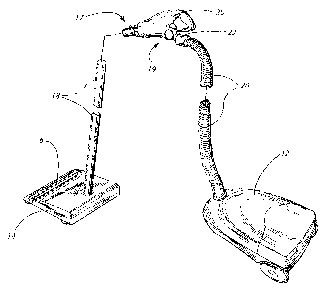
A floor care apparatus has a handle, connected to a hose, that pivots
about an axis substantially perpendicular to a longitudinal axis of a
terminal end of the hose. In this manner, the hose experiences less
mechanical stress during use and, when embodied on a canister vacuum
cleaner, a nozzle assembly connected to the handle has less tendency to tip
over. Preferably, the hose has a cuff mounted at the terminal end with a
hose insert therein. The hose insert has two stub shafts on opposing sides
of an opening that form a journal defining the handle pivoting axis. The
handle has two mating sections that clamshell about the journal and pinch
it in place. Each mating section has a bearing surface for receipt of the
journal and, when embodied as a cylinder, terminal ends of the journal
become inserted therein.

Revendications

Note : Les revendications sont présentées dans la langue officielle dans laquelle elles ont été soumises.


9
CLAIMS:
1. A floor care apparatus, comprising:
a hose having a longitudinal axis at a terminal end thereof; and
a handle connected to the terminal end that pivots about,
a transverse axis transverse to the longitudinal axis.
2. The floor care apparatus of claim 1, wherein the hose has a cuff
mounted at the terminal end.
3. The floor care apparatus of claim 1, wherein a hose insert
mounts within the terminal end.
4. The floor care apparatus of claim 3, wherein the hose insert
includes a journal defining the transverse axis.
5. The floor care apparatus of claim 4, wherein the handle includes
two mating sections each having a bearing surface, the bearing surfaces
pinching the journal when the two mating sections are joined together.
6. A floor care apparatus, comprising:
a base assembly;

a flexible hose, having a longitudinal axis at a terminal end thereof,
connected to the base assembly;
a nozzle assembly;
a wand connected to the nozzle assembly; and
a handle connected to the wand and pivotally connected to the
flexible hose such that the handle pivots about
a transverse axis transverse to the longitudinal axis.
7. The floor care apparatus of claim 6, wherein the flexible hose
has a cuff mounted at the terminal end.
8. The floor care apparatus of claim 7, wherein a hose insert
mounts within the cuff.
9. The floor care apparatus of claim 8, wherein the hose insert
includes a journal defining the transverse axis.
10. The floor care apparatus of claim 9, wherein the handle
includes two mating sections each having a bearing surface.
11. The floor care apparatus of claim 10, wherein the bearing
surfaces pinch the journal when the two mating sections are joined
together.
12. A canister vacuum cleaner, comprising:

11
a base assembly;
a flexible hose having a cuff and a hose insert therein connected to
the base assembly, the cuff having a longitudinal axis and the hose insert
having a journal defining a perpendicular axis substantially
perpendicular to the longitudinal axis;
a nozzle assembly;
a wand connected to the nozzle assembly; and
a handle connected at one end to the wand and at another end
pivotally connected to the journal such that the handle pivots about the
perpendicular axis.
13. The canister vacuum cleaner of claim 12, wherein the hose
insert has an opening in fluid communication with the nozzle assembly.
14. The canister vacuum cleaner of claim 12, wherein the hose
insert has a cutout region facilitating a wire.
15. The canister vacuum cleaner of claim 12, wherein the handle
has two mating sections each having a bearing surface, the bearing
surfaces pinching the journal when the two mating sections are joined
together.
16. The canister vacuum cleaner of claim 15, wherein one of the
bearing surfaces includes a cylinder and the journal has a cylinder terminal

12
end, an inner diameter of the cylinder being larger than an outer diameter
of the cylinder terminal end.
17. The canister vacuum cleaner of claim 16, wherein the cylinder
terminal end is inserted into the cylinder.
18. The canister vacuum cleaner of claim 15, wherein the two
mating sections clamshell about the journal.
19. The canister vacuum cleaner of claim 12, wherein the journal
embodies two stub shafts on opposite sides of the hose insert.
20. The canister vacuum cleaner of claim 19, wherein each of the
two stab shafts insert into a cylinder of the handle.

Description

Note : Les descriptions sont présentées dans la langue officielle dans laquelle elles ont été soumises.


CA 02460256 2006-07-10
74320-294
I
FLOOR CLEANING APPARATUS
WITH PIVOTAL HANDLE
Technical Field
The present invention relates generally to the floor care field, and,
more particularly, to a floor cleaning apparatus, such as a canister vacuum
cleaner, having a handle pivotally connected to a cleaning hose.
Background of the Invention
Canister vacuum cleaners in all of their designs and permutations
have become increasingly popular over the years. In general, canister
vacuum cleaners incorporate a base assembly which rides on wheels and a
nozzle assembly fluidly and mechanically connected thereto that sucks up
dirt and dust by operator movement across a dirt-laden floor. Specifically,
a rigid wand connects to the nozzle assembly and an operator manipulates
a handle thereof back and forth to cause the wand, and thereby the nozzle,
to sweep to and fro across the floor. In turn, the handle connects to a
flexible hose that also connects to the base assembly.

CA 02460256 2004-03-08
2
Problematically, the connection between the handle and the hose
typically involves ~.gid structures mechanically secured to one another
that cause the hose to undergo large mechanical stresses whenever the
handle moves relative thereto. As such, premature failure of the hose or
the electrical conductors therein can result.
Accordingly, the floor care arts have need of a handle that can
move relative to a l,ose without causing premature hose or other failures.
Summarv of the Invention
In accordance with the purposes of the present invention as
described herein, an improved floor care apparatus is provided. The
apparatus may take the form of a canister or an upright vacuum cleaner or
may embody an extraction cleaning device or other hereinafter developed
product having a hose connected to an operator handle.
In one embodiment, a floor care apparatus has a handle connected
to a hose such that the handle pivots about an axis substantially
perpendicular to a longitudinal axis of a terminal end of the hose.
Preferably, the hose has a rigid cuff mounted at the terminal end with a
hose insert therein. '1'he hose insert _has two stub shafts on opposite sides
thereof that forrn ajoumal defming rhe handle pivoting axis. The handle
has two mating sections that clamshell about the journal and pinch it in
place. Each of the mating sections has a bearing surface for receipt of the
joumal and are embodied as cylinders. Terminal ends of the jour.aal also
embody cylinders and an inner diameter of the bea_rin.g surface cylinder is

CA 02460256 2006-07-10
74320-294
3
greater than an outer diameter of the journal cylinder
terminal end so that the journal terminal end can be
inserted into the bearing surface cylinder. During use,
this arrangement lessens the mechanical stresses exerted on
the hose when the handle moves relative thereto. Even
further, when the floor care apparatus embodies a canister
vacuum cleaner, a nozzle assembly thereof has less tendency
to tip over during movement of the handle.
In another embodiment, the invention provides a
floor care apparatus, comprising: a hose having a
longitudinal axis at a terminal end thereof; and a handle
connected to the terminal end that pivots about a transverse
axis transverse to the longitudinal axis.
In a further embodiment, the invention provides a
floor care apparatus, comprising: a base assembly; a
flexible hose, having a longitudinal axis at a terminal end
thereof, connected to the base assembly; a nozzle assembly;
a wand connected to the nozzle assembly; and a handle
connected to the wand and pivotally connected to the
flexible hose such that the handle pivots about a transverse
axis transverse to the longitudinal axis.
In a still further embodiment, the invention
provides a canister vacuum cleaner, comprising: a base
assembly; a flexible hose having a cuff and a hose insert
therein connected to the base assembly, the cuff having a
longitudinal axis and the hose insert having a journal
defining a perpendicular axis substantially perpendicular to
the longitudinal axis; a nozzle assembly; a wand connected
to the nozzle assembly; and a handle connected at one end to
the wand and at another end pivotally connected to the
journal such that the handle pivots about the perpendicular
axis.

CA 02460256 2006-07-10
74320-294
3a
In the following description there is shown and
described one possible embodiment of this invention, simply
by way of illustration of one of the modes best suited to
carry out the invention. As it will be realized, the
invention is capable of other different embodiments, and its
several details are capable of modification in various,
obvious aspects all without departing from the invention.
Accordingly, the drawings and descriptions will be regarded
as illustrative in nature and not as restrictive.
Brief Description of the Drawings
The accompanying drawings incorporated in and
forming a part of the specification, illustrate several
aspects of the present invention, and together with the
description serves to explain the principles of the
invention. In the drawings:
Figure 1 is a perspective view of a floor care
apparatus, in this instance a canister vacuum cleaner,
constructed in accordance with the teachings of the present
invention;
Figure 2a is a side view of a cleaner handle
having a wand-end pivoted upward relative to a hose;

CA 02460256 2004-03-08
4
Figure 2b is a side view of a cleaner ha dle having a wand-end
pivoted downward relative to a hose;
Figure 3 is a side view of an interior of the handle connected to the
hose;
Figure 4 is a perspective view of a cuff and a hose insert therein
fitted at a terminal end of a hose; and
Figure 5 is a side view of a jol of a hose insert before
connection to bearing surfaces of a handle.
Reference will now be made in detail to the present invention, an
example of which is illustrated in the accompanying drawing.
Detailed Description of the Invention
Reference is now made to Figure 1 showing a floor care apparatus
of the present invention. The apparatus illustrated exemplifies a canister
vacuurn cleaner 10 comprised generally of a base assembly 12 and a
nozzle assembly 14. Although not shown, the base assembly contains a
suction fan and motor that cooperates with an agitator 16 in the nozzle
assembly for suc k' g up dirt and dust in a manner well known to those
skilled in the arL A wand 18 mechanically and. fluidly connects to the
nozzle assembly and facilitates the sucking up of dirt and dust. in various
embodiments, it may comprise a unitary, telescopic or connecting section
of pipe, such as an aluminum pipe. Near the base assembly, a hose 20,
flexible for user manipulation, connects thereto and likewise facihtates the
sucking up of dirt and dust. In some embodiments, a cuff 22 fonned of a

CA 02460256 2004-03-08
rigid piece of plastic, metal or other occupies or mounts to a terrninal end
of the hose to provide a wieldy mechanical coixpling region.
Finally, a handle 30 having at least two ends 17, 19 connects
mechanically and fluidly to both the wand 18 and the hose 20 and/or cuff
5 22. As will be described in greater detail below, the handle of the present
invention advantageously provides users the ability to rotate or pivot the
handle about an axis substantially perpendicular to a longitudinal axis of
the cuff and/or terrninal end of the hose thereby reducing the mechanical
stresses applied to the hose during use and reducing the tendency of the
nozzle assembly to tip over.
By comparing Figure 2a with 2b, skilled artisans will observe that a
user may pivot the handle wand-end 31 upward relative to the hose 30 in
the direction of rotation arrow A or downward relative to the hose 30 in
the direction of rotation arrow B, respectively. Specifically, users may
pivot the handle 30 about an axis 50 (shown generall-Y in a direction into
the paper) that, in t=,~rn, exists transverse to the longittxdinal axis of a
terminal end of the hose 20. As shown, an axis 52 represents an axis
parallel the longitudinal axis of the ~~:erminal end of the hose. Since a cuff
22 occupies the te inal er~d of the hose in all -the figares, the axis 52 also
represents an axis parallel to the longitudinal axis of the cuff and the axis
50 exists transverse to all such axises. l.n a rnore prefbrred embodiment,
the haildle pivoting axis 50 exists s-u_bstantially perpendicular to the
longitudinal axis of the hose terminal end or the cuff.
Appreciating that varieties of :mechanica:1 features will allow the
described handle pivoting tec _ que, refer now to Figures 3, 4 and 5 for a

CA 02460256 2004-03-08
6
specific embodimena, thereof As before, a cuff 22 occupies a terrninal end
of the hose 20. A hose insert 40, having openings 41, 43 on either ends
thereof to facilitate fiuid co cation between the base and nozzle
assemblies, mounts to and resides within the cuff 22. In one embodiment,
the mounting occurs as a result of a friction or an interference fit. In other
embodiments, the mounting occurs as a result of mechanical fasteners
holding the hose insert to the cuff or via weldiing or other.
Atop the hose insert 40 sits a cylinder 45 having two stub shafts 47,
49 emanating on opposite sides of the opening 41. Together, the two stub
shafts forrn a journal along the axis 50 about whicll the handle will pivot.
In a preferred embodiment, the terrninal ends of the journal embody
cylinders 51, 53 that become pinched between Vvo corresponding larger-
diameter cylinders 55, 57 on bearing,; surfaces 59, 61 of left and right
mating sections 30-L, 30-R of the handle 30. Sknce the inner diarneter dl
of the cylinders 55, 57 of the bearing surfaces exceeds the outer diameter
d2 of the cylinder terrninal ends of the joumal 51, 53, the journal terminal
ends easily fit wiffi.i.n the cylinders when the two mating surfaces 30-L, 30-
IZ. are joined together. Preferably, the two mating sections join via
mechanical fasteners, such as screws 32, rivets, cl ps or the lilse, that
extend through both mating sections and, when fastened, cause the mating
sections to clamshell about the journal.
In addition, the hose insert 40 may contain a cutout region 63 to
facilitate or accommodate an electrical wire 65, or odier, that traverses
generally the entirety of length of the hose 20 to provide an electrical

CA 02460256 2004-03-08
7
connection between a power source (not shown) and an operator power or
floor-setting switcb. 70.
In other embodiments, the jo-arnal of the hose insert may include a
unitary shaft or axle that extends between both. of the bearing sur.faces of
the handle and rnay or may not cross the opening 41. Alternatively, the
shafts or axles may actnally spin or turn relative to the hose insert instead
of being stationarily mounted. Still alternatively, the axles or shafts may
mount directly on the handle with the corresponding bearing surfaces
existing on the hose insert. In other words, the jo a.l and bearing
surfaces may exist on either the hose insert or the handle and may be
designed to interchange with one another.
In other handle embodiments, the two mating sections have interior
walls that together defme a flow conduit 75 to fluidly connect the hose
insert opening 41 to the wand 18. Ultimately, this serves to fluidly
connect the nozzle assembly to the base assembly.
In still other eynbodiments, a handle wall 61 defines an opening 69
for receiving an operator's hand during use ancl may or may not contain
contours for receipt of 'mdividual fingers.
The foregoing was chosen and described to provide the best
illustration of the principles of the invention and its practical application
to
thereby enable one of ordinary skill in the art to utilize the invention in
various embodiments and with varioas modifications as are suited to the
particular use contemplated. All such modifications and variations are
within the scope of the invention as determined by the appended claims

CA 02460256 2004-03-08
8
when interpreted in accordance with the breadth to which they are fairly,
legally and equitably entitled.

Dessin représentatif
Une figure unique qui représente un dessin illustrant l'invention.
États administratifs

2024-08-01 : Dans le cadre de la transition vers les Brevets de nouvelle génération (BNG), la base de données sur les brevets canadiens (BDBC) contient désormais un Historique d'événement plus détaillé, qui reproduit le Journal des événements de notre nouvelle solution interne.

Veuillez noter que les événements débutant par « Inactive : » se réfèrent à des événements qui ne sont plus utilisés dans notre nouvelle solution interne.

Pour une meilleure compréhension de l'état de la demande ou brevet qui figure sur cette page, la rubrique Mise en garde , et les descriptions de Brevet , Historique d'événement , Taxes périodiques et Historique des paiements devraient être consultées.

Historique d'événement

Description Date
Le délai pour l'annulation est expiré 2010-03-08
Lettre envoyée 2009-03-09
Accordé par délivrance 2007-06-05
Inactive : Page couverture publiée 2007-06-04
Exigences relatives à la révocation de la nomination d'un agent - jugée conforme 2007-05-09
Inactive : Lettre officielle 2007-05-09
Exigences relatives à la nomination d'un agent - jugée conforme 2007-05-09
Demande visant la révocation de la nomination d'un agent 2007-04-10
Demande visant la nomination d'un agent 2007-04-10
Préoctroi 2007-03-21
Inactive : Taxe finale reçue 2007-03-21
Un avis d'acceptation est envoyé 2007-02-16
Lettre envoyée 2007-02-16
Un avis d'acceptation est envoyé 2007-02-16
Inactive : CIB enlevée 2007-02-09
Inactive : CIB attribuée 2007-02-09
Inactive : CIB en 1re position 2007-02-09
Inactive : CIB enlevée 2007-02-09
Inactive : Approuvée aux fins d'acceptation (AFA) 2007-01-31
Modification reçue - modification volontaire 2006-09-29
Modification reçue - modification volontaire 2006-07-10
Inactive : Dem. de l'examinateur art.29 Règles 2006-04-25
Inactive : Dem. de l'examinateur par.30(2) Règles 2006-04-25
Inactive : CIB de MCD 2006-03-12
Lettre envoyée 2005-08-15
Demande publiée (accessible au public) 2004-12-24
Inactive : Page couverture publiée 2004-12-23
Lettre envoyée 2004-05-11
Inactive : CIB attribuée 2004-05-07
Inactive : CIB en 1re position 2004-05-07
Lettre envoyée 2004-04-20
Inactive : Certificat de dépôt - Sans RE (Anglais) 2004-04-13
Demande reçue - nationale ordinaire 2004-04-13
Toutes les exigences pour l'examen - jugée conforme 2004-03-31
Exigences pour une requête d'examen - jugée conforme 2004-03-31
Requête d'examen reçue 2004-03-31

Historique d'abandonnement

Il n'y a pas d'historique d'abandonnement

Taxes périodiques

Le dernier paiement a été reçu le 2007-02-20

Avis : Si le paiement en totalité n'a pas été reçu au plus tard à la date indiquée, une taxe supplémentaire peut être imposée, soit une des taxes suivantes :

  • taxe de rétablissement ;
  • taxe pour paiement en souffrance ; ou
  • taxe additionnelle pour le renversement d'une péremption réputée.

Les taxes sur les brevets sont ajustées au 1er janvier de chaque année. Les montants ci-dessus sont les montants actuels s'ils sont reçus au plus tard le 31 décembre de l'année en cours.
Veuillez vous référer à la page web des taxes sur les brevets de l'OPIC pour voir tous les montants actuels des taxes.

Historique des taxes

Type de taxes Anniversaire Échéance Date payée
Taxe pour le dépôt - générale 2004-03-08
Enregistrement d'un document 2004-03-08
Requête d'examen - générale 2004-03-31
Enregistrement d'un document 2005-07-05
TM (demande, 2e anniv.) - générale 02 2006-03-08 2006-02-16
TM (demande, 3e anniv.) - générale 03 2007-03-08 2007-02-20
Taxe finale - générale 2007-03-21
TM (brevet, 4e anniv.) - générale 2008-03-10 2008-02-14
Titulaires au dossier

Les titulaires actuels et antérieures au dossier sont affichés en ordre alphabétique.

Titulaires actuels au dossier
PANASONIC CORPORATION OF NORTH AMERICA
Titulaires antérieures au dossier
CHAD D. OVERVAAG
JAMES T. CROUCH
Les propriétaires antérieurs qui ne figurent pas dans la liste des « Propriétaires au dossier » apparaîtront dans d'autres documents au dossier.
Documents

Pour visionner les fichiers sélectionnés, entrer le code reCAPTCHA :


Pour visualiser une image, cliquer sur un lien dans la colonne description du document. Pour télécharger l'image (les images), cliquer l'une ou plusieurs cases à cocher dans la première colonne et ensuite cliquer sur le bouton "Télécharger sélection en format PDF (archive Zip)" ou le bouton "Télécharger sélection (en un fichier PDF fusionné)".

Liste des documents de brevet publiés et non publiés sur la BDBC .

Si vous avez des difficultés à accéder au contenu, veuillez communiquer avec le Centre de services à la clientèle au 1-866-997-1936, ou envoyer un courriel au Centre de service à la clientèle de l'OPIC.


Description du
Document 
Date
(aaaa-mm-jj) 
Nombre de pages   Taille de l'image (Ko) 
Description 2004-03-07 8 518
Dessins 2004-03-07 6 298
Abrégé 2004-03-07 1 40
Revendications 2004-03-07 4 158
Dessin représentatif 2004-05-12 1 18
Description 2006-07-09 9 497
Revendications 2006-07-09 4 109
Courtoisie - Certificat d'enregistrement (document(s) connexe(s)) 2004-04-19 1 105
Certificat de dépôt (anglais) 2004-04-12 1 159
Accusé de réception de la requête d'examen 2004-05-10 1 176
Rappel de taxe de maintien due 2005-11-08 1 109
Avis du commissaire - Demande jugée acceptable 2007-02-15 1 162
Avis concernant la taxe de maintien 2009-04-19 1 171
Correspondance 2007-03-20 1 39
Correspondance 2007-04-09 7 358
Correspondance 2007-04-11 7 356
Correspondance 2007-05-08 1 13
Correspondance 2007-05-08 1 16