Note : Les descriptions sont présentées dans la langue officielle dans laquelle elles ont été soumises.
CA 02462304 2004-03-30
WO 03/029781 PCT/US02/31385
DETECTION CELL
BACKGROUND OF THE INVENTION
FIELD OF THE INVENTION
The invention relates generally to photometrically analyzing a sample in a
chemical detection system. More particularly, the invention is directed to an
S apparatus and method for uniformly illuminating a sample in a micro-channel
array or
detection cell of an electrophoresis system using a prism arrangement.
DESCRIPTION OF RELATED ART
The separation and analysis of chemical samples is widely used in both
chemistry and biotechnology. In order to increase the speed and efficiency at
which
chemical samples are evaluated, chemical samples are separated into their
component
parts and simultaneously analyzed.
One such separation technology, electrophoresis, is used in DNA sequencing,
protein molecular weight determination, genetic mapping, and other types of
processes used to gather large amounts of analytical information about
particular
chemical samples. Electrophoresis is the migration of charged colloidal
particles or
molecules through a solution under the influence of an applied electric field
usually
provided by immersed electrodes, where the colloidal particles are a
suspension of
finely divided particles in a continuous medium.
Historically, a polymer gel containing the finely divided particles was placed
between two glass plates and an electric field applied to both ends of the
plates. This
method, however, offered a low level of automation together with long analysis
times.
More recently, capillary electrophoresis (hereinafter "CE") was developed,
which has the added advantages of speed, versatility and low running costs.
Operation of a CE system involves application of a high voltage (typically 10-
30kV)
across a narrow bore capillary (typically 25-100 ,um). The capillary is filled
with
CA 02462304 2004-03-30
WO 03/029781 PCT/US02/31385
electrolyte solution which conducts current through the inside of the
capillary. The
ends of the capillary are dipped into reservoirs filled with the electrolyte.
Electrodes
made of an inert material such as platinum are also inserted into the
electrolyte
reservoirs to complete the electrical circuit. A small volume of sample is
injected into
one end of the capillary. Application of the voltage causes movement of sample
ions
towards their appropriate electrode. Different sample ions arrive at a
detection part of
the capillary at different times. The sample may be labeled with a fluorescent
marker
so that when the sample passes through a beam of light at the detector the
fluorescent
marker fluoresces and the fluorescence is detected by a detector, usually a UV
detector, as an electric signal. The intensity of the electric signal depends
on the
amount of fluorescent marker present in the detection zone. The plot of
detector
response versus time is then generated, which is termed an electropherogram.
CE is a particularly preferred separation method, as it allows the use of high
electric fields due to the capillary tube efficiently dissipating the
resulting heat
produced by the electric field. As such, the separations achieved are much
better than
the more traditional electrophoretic systems. In addition, multiple capillary
tubes may
be closely spaced together and used simultaneously to increase sample
throughput.
In traditional CE systems, analysis or detection of the separated components
is
performed while the sample is still located within the capillary and may be
accomplished using photometric techniques such as adsorbance and fluorescence.
These photometric techniques direct excitation light toward the capillary
tube. Light
emitted from the sample (e.g., fluorescence) is then measured by a detector,
thereby
providing information about the separated components. Therefore, in these
systems,
excitation light directed at the sample, as well as light emitted from the
sample, must
be transmitted through the capillary's walls. A drawback of this approach is
that the
fused silica capillaries typically used in capillary electrophoresis are poor
optical
elements and cause significant scattering of light. The problem associated
with light
scattering is exacerbated by having multiple capillaries disposed side-by-
side, as
scattered excitation light from one capillary interferes with the detection of
samples in
neighboring capillaries.
2
CA 02462304 2004-03-30
WO 03/029781 PCT/US02/31385
One approach to solving the problem of on-capillary detection has been to
detect a sample after the sample emerges from the capillary in a detection
cell having
superior optical characteristics, e.g., a flat quartz chamber. In this system,
a sample is
transported from the outlet of a capillary to the detection cell by
electrophoresis under
the influence of the same voltage difference used to conduct the
electrophoretic
separation. Examples of this type of system are disclosed in U.S. Patent No.
5,529,679, which is incorporated herein by reference.
A variation of the above system replaces the capillary tubes with a series of
parallel micro-channels formed in a plate or chip, where the micro-channels
are in
fluid communication with a detection cell in a manner similar to that
described above.
This CE layout is known as a micro-channel array.
While addressing some of the abovementioned problems, the detection cell
type CE system has drawbacks of its own. For example, excitation energy, such
as
light from a laser, has the tendency to scatter, thereby diminishing the
energy's
intensity as it transmitted through the detection cell.
A partial cross-section of a prior art detection cell 102 is shown in Figure
1A.
The detection cell 102, typically made from glass substrate, forms a cavity
108, which
is filled with an electrolytic polymer 110 containing a sample to be detected.
The
cavity 108 is then typically covered with a transparent cover 118. Excitation
light
104, typically from a laser, enters the detection cell 102 at a first end 112.
Because
the first end 112 is normal to the excitation light 104, the light 104 does
not scatter,
i.e., reflect or refract, when passing into the detection cell, from air to
glass.
However, when the light 104 passes through the boundary 106 between the
detection
cell and the polymer 110, the light is refracted. This is due to the angle or
slope of the
boundary 106, and the difference in refractive indices of the glass and
polymer. The
angle or slope of the boundary 106 is caused by current etching and mastering
technologies, which are typically unable to produce optically flat vertical
cavity walls
in glass or plastic cavities 108 of the required dimensions.
The refracted light obeys the law of refraction, i.e.,
RI, sin(AI)=RIR sin(AR)
where RI, = first refractive index;
3
CA 02462304 2004-03-30
WO 03/029781 PCT/US02/31385
AI = angle of incidence;
RIR = second refractive index; and
AR = angle of refraction.
As the polymer has a refractive index (approximately 1.41) less than the
refractive index of glass (approximately 1.52), the angle of refraction is
larger than the
angle of incidence and the light bends further away from the normal to the
boundary
106. Much of the excitation light is lost due to light escaping 116 out of the
detection
cell instead of being trapped in the cavity by Fresnel reflection. This
degrades the
intensity of excitation light incident on the samples, which in turn adversely
affects
the strength of the detected signal. Furthermore, refracted light rays may
also reflect
114 off the internal surfaces of the cavity 108 causing interference and,
therefore,
degradation of the detection signal. In other words, the curved or angled
interfaces or
boundaries in combination with the unfavorable refractive index change at the
glass to
polymer boundary or interface, leads to unsatisfactory light intensity and
quality, and
consequently poor sample detection.
Moreover, the first end 112 through which the light first passes must be
optically flat so that the light is not distorted. This requires the first end
112 to be
polished, which is both expensive and time consuming.
Also, the substrate through which the light passes before entering the cavity
may contain defects, such as voids, contaminants, or non-homogeneous material
that
creates density gradients. These defects can cause the light to scatter,
refract, reflect ,
or the like, all of which degrade the light quality and hence detected signal.
In light of the above, there is a need for a more efficient means for
directing
light into a cavity while addressing the abovementioned drawbacks.
BRIEF SUMMARY OF THE INVENTION
According to an embodiment there is provided a detection cell of an
electrophoresis system. The detection cell includes a substrate that defines a
cavity.
The cavity may have a substantially planar floor and at least one wall with an
opening
there through. The detection cell also may include a prism disposed adjacent
the
4
CA 02462304 2004-03-30
WO 03/029781 PCT/US02/31385
opening. The prism is configured to redirect light through the opening into
the cavity
at an angle substantially parallel to the floor.
The prism may include a transparent exit surface disposed adjacent, and
bounding, the opening and a reflector inclined at an acute angle to the
transparent
surface. The reflector is configured to redirect light substantially
orthogonally
through the transparent surface into the cavity. The prism may also include a
transparent entry surface disposed substantially perpendicular to the exit
surface.
In another embodiment, a shaft is bored at least partially through the
substrate
adjacent the opening. The shaft is inclined substantially perpendicular to the
floor.
The prism is then positioned within the shaft.
In an alternative embodiment, the prism includes an additional reflector
disposed substantially parallel to the reflector. The additional reflector is
configured
to redirect light from a light source at the reflector.
Further, according to various embodiments there is provided an additional
prism disposed adjacent an orifice in an additional wall of the cavity
opposing the
opening. The additional prism is configured to redirect light exiting through
the
orifice away from the cavity to avoid light scatter. The additional prism may
include a
transparent exit surface disposed adjacent the orifice and a reflector
inclined at an
acute angle to the transparent exit surface. The reflector is configured to
redirect light
away from the cavity at an angle substantially perpendicular to the floor.
Still further, according to various embodiments there is provided a method for
illuminating a chemical sample. A chemical sample is positioned in the cavity.
Light
is firstly directed at a prism. The prism is disposed adjacent an opening
leading into a
cavity containing a chemical sample. Subsequently the light is reflected
within the
prism to pass through the opening and into the cavity to illuminate the
chemical
sample.
Various embodiments address the above described drawbacks by guiding light
into a detection cell using a light guide, such as a prism. The light guide
provides a
controlled reflector near the entry of a cavity. The reflector of the light
guide is
isolated from the chemistry in the cavity by a transparent surface that may
form part of
the light guide itself. In an alternate embodiment an additional reflector of
the light
CA 02462304 2004-03-30
WO 03/029781 PCT/US02/31385
guide redirects light to the reflector of the light guide so that the light
may be directed
into the detection cell from any chosen orientation. The transparent surface
of the
light guide forms part of the light guide's wall. The various surfaces of the
light guide
are made optically flat to eliminate beam reshaping and refraction issues.
Also, since
the transparent surface is flat, the unfavorable index of the polymer does not
affect the
light beam entry into the cavity.
Furthermore, cavity illumination overcomes the problems of not having a
clean optical surface on the edge of the substrate by bringing the light in
though a
shaft somewhere within the edges of the substrate. The cross-section of the
shaft can
be either square, round, or other polygonally shaped form.
BRIEF DESCRIPTION OF THE DRAWINGS
For a better understanding of the nature and objects of the invention,
reference
should be made to the following detailed description, taken in conjunction
with the
accompanying drawings, in which:
Figure 1 is a partial cross-section of a prior art detection cell;
Figure 2A is a partial top view of a detection cell according to an embodiment
of the invention;
Figure 2B is a partial side view of the detection cell shown in Figure 2A;
Figure 3 is a close-up view of part of the detection cell shown in Figure 2B;
Figure 4A is a partial top view of a detection cell according to another
embodiment of the invention;
Figure 4B is a partial side view of the detection cell shown in Figure 4A;
Figures 5A-5D are isometric three dimensional views of various prisms
according to various different embodiments of the invention;
Figure 6 is a partial side view of a detection cell according to yet another
embodiment of the invention;
Figure 7A is a partial top view of a detection cell according to yet another
embodiment of the invention;
Figure 7B is a partial side view of the detection cell shown in Figure 7A;
6
CA 02462304 2004-03-30
WO 03/029781 PCT/US02/31385
Figures 8A-8C are partial top views of detection cells according to various
different embodiments of the invention; and
Figure 9 is a flow chart of a method for illuminating a chemical sample
according to an embodiment of the invention.
S Like reference numerals refer to corresponding parts throughout the several
views of the drawings.
DETAILED DESCRIPTION OF THE INVENTION
For ease of explanation the following is described in use with a micro-channel
plate. However, it should be appreciated that the described embodiments may be
used
with any chemical analysis device where control of light through a boundary
between
substances having different refractive indices is important, such as in a
capillary
electrophoresis device.
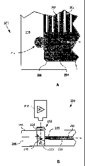
Figure 2A is a partial top view of a detection cell 200 according to an
embodiment of the invention. The detection cell 200 may comprise a substrate
206
having a cavity 204 formed therein, as best seen in Figure 2B. The substrate
may be a
transparent material such as glass or plastic. Some candidate materials are
borosilicate glass (such as SCHOTT BOROFLOAT or 0211 CORNING glass),
acrylic (such as polyrnethylmethacrylate (PMMA)), or ZEONOR/ZEONEX grade
plastics.
The cavity 204 is a shallow hollow for receiving a chemical sample and has an
opening 218 extending therefrom. The cavity 204 is filled with an electrolyte
solution
such as an electrolytic polymer. In one embodiment, the polymer is APPLIED
BIOSYSTEMS POP-6 POLYMER GEL MATRIX. The detection cell 200 may also
include an inlet 208 for filling the first cavity 204 with the electrolyte
solution.
Figure 2B is a partial side view of the detection cell 200 shown in Figure 2A.
A cover 214 covers the substrate 206. Because the cavity 204 has a shallow
depth, it
is imperative that light entering the cavity 204 travels substantially
parallel to the floor
222 of the cavity 204, so as not to scatter. A cavity 212 may be located
adjacent the
cavity 204. The light guide 212 is an optical instrument that contains
reflecting
elements, such as mirrors and prisms, to permit the displacement of light. To
position
7
CA 02462304 2004-03-30
WO 03/029781 PCT/US02/31385
the light guide 212 adjacent to the cavity 204, a shaft 220 is first bored
through the
cover 214 and substrate 206 so that part of the cavity 204 is in fluid
communication
with the shaft 220. The shaft may be square in cross-section, but
alternatively may be
any shape, such as rectangular or circular as shown. In one embodiment, the
shaft is
S 2mm square in cross-section and is bored or drilled by ultrasonic drilling
with an
abrasive media or slurry. The abrasive media are either larger than the cavity
(approximately 50 microns) to keep the abrasive media from entering the cavity
or
smaller than the cavity (approximately 8 to 20 microns) so that the abrasive
media can
be easily flushed out of the cavity. Alternatively, de-ionized and filtered
water is
pumped from an opposing side of the cavity with a pressure sufficient to keep
the
slurry from getting into the cavity.
The light guide 212 is then inserted into the shaft 220. The light guide is
then
bonded into place by an epoxy 216 and 224. Alternatively, the light guide can
be
fused to the plate (see Figures 2A, 2B, 4A, and 4C). Optionally, gaskets or
seals
could also be used to keep the fluid in the cavity from escaping. In this way,
the
surface of the light guide 212 bounding the cavity blocks the fluid
communication
between the cavity 204 and the shaft 220 or at least to block fluid from
escaping the
cavity.
Figure 3 is a close-up view of the light guide 212 of the detection cell 200
shown in Figure 2B. The cavity 204 is configured to receive a chemical sample
contained within an electrolyte solution 304. The light guide also comprises a
transparent surface 308 bounding at least part of the cavity 204 and a
reflector 302
inclined at an acute angle 314 to the transparent surface 308. The reflector
308 is a
reflective surface that is configured to redirect light 310 substantially
orthogonally
through the transparent surface 308 into the cavity 204. The light guide 212
may also
include an additional transparent. surface 306 that is inclined substantially
perpendicular to the transparent surface 308. In one embodiment, the reflector
302,
transparent surface 308 and additional transparent surface 306 form a prism.
More
specifically, the prism may be a right-angled prism with the reflector being
the
hypotenuse. The outer surface of the reflector may be silvered, coated, or
metallized
CA 02462304 2004-03-30
WO 03/029781 PCT/US02/31385
with a metallic substance to better reflect the incoming light beam 310. Also,
the light
guide 212 may be made of glass such as a BK-7.
The transparent surface 308 seals the open end of the cavity 204 so that the
electrolyte solution 304 cannot flow out of the cavity into the shaft 220
(Figure 2B).
The incoming light beam 310 is directed into the light guide 212 and
thereafter
redirected as a reflected beam 312 that passes into the cavity orthogonally
through the
transparent surface 308. In this way, the light is not refracted when entering
the cavity
204. Therefore, the entry of the reflected beam 312 into the cavity 204 can be
accurately controlled and scatter reduced.
In an alternative embodiment, the additional transparent surface 306 may be
inclined relative to the transparent surface 308. The additional transparent
surface
306 must, however, always remain substantially orthogonal to the incoming
light 310.
In this embodiment, the angle 314 would differ to that for the previous
embodiment to
ensure that the reflected beam 312 passes orthogonally through the transparent
surface
308.
Figure 4A is a partial top view of a detection cell 400 according to another
embodiment of the invention, and Figure 4B is a partial side view of the
detection cell
400 shown in Figure 4A. In this embodiment a light source 402 projects a light
beam
404 in a direction substantially parallel to the direction of the desired
reflected beam
within the cavity 412. To accomplish this, a light guide 406 is used. In this
embodiment the light guide 406 includes a reflector 410 and an additional
reflector
408. The additional reflector 408 redirects an incoming light beam 404 at the
reflector 410. The reflector 410 then redirects a reflected light beam 416
into the
cavity as described in relation to Figures 2A, 2B, and 3.
The light guide 406 comprises a rhomboidal prism similar to that shown in
Figure SA. Alternatively, the light guide 406 may comprise two right-angled
prisms
similar to those shown in Figure SC. Still further, the reflectors 408 and 410
of the
light guide 406 may alternatively comprise two parallel mirrors. In all of the
aforementioned embodiments the light guide must include a transparent surface
414
through which the reflected light beam 416 orthogonally passes into the cavity
412. If
the reflected light beam is not orthogonal to the transparent surface 414, the
reflected
9
CA 02462304 2004-03-30
WO 03/029781 PCT/US02/31385
light beam will refract and, thereby, adversely affect the quality of light in
the cavity
412 and hence any detected signal. Figures SA-SD are isometric three
dimensional
views of various prisms according to various different embodiments of the
invention.
Figure SA shows a rhomboidal prism with a first reflector 502 parallel to a
second
reflector 504. Figure SB shows a variation of the rhomboidal prism where a
first
reflector 506 has been rotated through ninety degrees about axis 510, in
relation to the
second reflector 508. This prism not only displaces an incoming light beam by
the
distance between the reflectors 506 and 508 but also rotates the beam through
ninety
degrees about axis 510.
Figure SC shows two right-angled prisms 512 and 514. These prisms can be
rotated relative to one another to adjust for light beam entry orientation as
well as
light beam exit orientation. Figure SD is a circular cylindrical prism 516.
Notice that
flat surfaces 518 are necessary at the light beam entry and exit surfaces to
avoid beam
shaping or distortion from the cylindrical wall shape. It should be
appreciated that the
light guide and/or prism can be any shape other than that described above,
such as an
elliptical cylindrical prism or the like.
Therefore, to summarize, the light guide's reflective surfaces may be
angularly
offset or linearly offset to allow the light to enter from any direction (see
Figures SB
and SC). If light enters vertically from above or below the detection cell,
only the
bottom half of the light guide is required (see Figures 2A and 2B). The light
guide
may be made from multiple and separate components (see Figure SC), but in its
simplest form it is made of a single component. The light guide cross-
sectional shape
is square or cylindrical, but it is not limited to these shapes (see Figures
SA-SD). The
light guide can be bonded into the detection cell with an adhesive (such as
epoxy) or
fused to the plate (see Figures 2A, 2B, 4A, and 4C). Alternatively, gaskets or
seals
could be used to keep the fluid in the cavity from escaping. The light guide's
reflective surfaces may be mirrorized but could be any interface condition
that causes
light to totally internally reflect such as an optical coating or interface
with a lower
refractive index fluid.
Figure 6 is a partial side view of a detection cell 600 according to yet
another
embodiment of the invention. In this embodiment a substrate 602 defines both a
CA 02462304 2004-03-30
WO 03/029781 PCT/US02/31385
cavity 604 having a substantially planar floor and an additional cavity 606.
The cavity
604 has an opening therethrough leading into the additional cavity 606. In
use, a
cover 606 is placed directly onto of the substrate 602. The cover 606 includes
an
integrally formed prism 608 for redirecting light into the cavity 604. It
should
however be appreciated that the prism 608 may be integrally formed with any
part of
the detection cell 600, so long as it causes light to be redirected into the
cavity 604
substantially parallel to the floor of the cavity 604.
a prism disposed adjacent said opening, where said prism is configured to
redirect light through said opening into said cavity in a direction
substantially
parallel to said floor.
Figure 7A is a partial top view of a detection cell 700 according to yet
another
embodiment of the invention, and Figure 7B is a partial side view of the
detection cell
700 shown in Figure 7A. As explained above in relation to Figure l, once a
light
beam has traversed a cavity 710 it would normally strike a wall 708 opposing a
1 S transparent surface 706 where the light beam enters the cavity 710. Due to
manufacturing processes, as explained above, the wall 708 of the cavity has a
curved
or convex shape. This shape in combination with the different refractive
indices of
the electrolyte solution and the substrate refract the light at the wall 708
causing
unwanted scattering of the light beam and possible reflections increasing
background
and stray light. To address this problem an additional light guide 704 can be
positioned on the opposing side of the cavity from light guide 702. The light
beam
now has a outlet from the cavity and, therefore, does not scatter. The
additional light
guide 704 may be designed to direct the exiting light beam in any desired
direction.
Figures 8A-8C are partial top views of detection cells according to various
different embodiments of the invention. To alleviate the problems described in
the
description of Figure 6 various other embodiments may be utilized. Figure 8A
shows
a curved exit channel 802 through which the exiting light beam can pass. The
exit
channel is supplied with electrolyte solution from the cavity 804 and inlet
806. In this
way light scatter is diverted away from the cavity 804. Figure 8B shows both
an entry
channel 808 and an exit channel 810 terminating in a part 812. In this way
light
scatter is avoided as the light passes into the port 812. Figure 8C shows an
exit
11
CA 02462304 2004-03-30
WO 03/029781 PCT/US02/31385
channel 814 and a flat plate 816 bonded to the side of the exit channel 814.
The flat
plate is made from a material with a black opaque surface that acts as a beam
stop. In
this way light scatter is avoided as the light is absorbed by the flat plate
816.
Figure 9 is a flow chart of a method 900 for illuminating a chemical sample
according to an embodiment of the invention. First, a substrate 206 (Figure
2B)
having a cavity 204 (Figure 2B) and a light guide 212 (Figure 2B) is provided
902. A
shaft 220 (Figure 2B) is then bored 904 through the substrate, as described
above.
The light guide is positioned 906 within the shaft and secured 907 in place by
bonding
the light guide into place or by fusing the light guide with the substrate.
The chemical sample is separated 908 as follows. A small volume of a
chemical sample is injected into capillaries or micro-channels 202 (Figure 2)
and an
electric field applied across the polymer, which causes movement of chemical
sample
ions through the polymer. Different chemical sample ions arnve at a detection
cavity
of the detection cell at different times. The chemical sample may be labeled
with a
fluorescent marker so that when the sample passes through a beam of light at
the
detector, the fluorescent marker fluoresces and the fluorescence is detected
as an
electric signal.
Light is then directed 910 at the light guide from a light source 210 (Figure
2B), such as a laser. Only in the embodiment where the light guide has two
reflectors
(Figure 4A and 4B), the light is redirected 912 by an additional reflector.
The light is
subsequently reflected 914 by the additional reflector (or reflector in the
embodiment
with only one reflector - Figure 2A and 2B) orthogonally through the
transparent
surface into the cavity.
A signal is then detected 916 by a detector. The intensity of the electric
signal
depends on the amount of fluorescent marker present in the detection zone and
the
amount of light exciting it. The electropherogram plot of detector response
with time
may be generated from the detected signal.
The foregoing descriptions of specific embodiments of the present invention
are presented for purposes of illustration and description. They are not
intended to be
exhaustive or to limit the invention to the precise forms disclosed, obviously
many
modifications and variations are possible in view of the above teachings. For
12
CA 02462304 2004-03-30
WO 03/029781 PCT/US02/31385
example, the use of the word orthogonal should not be taken literally, but
rather as
approximately orthogonal. The embodiments were chosen and described in order
to
best explain the principles of the invention and its practical applications,
to thereby
enable others skilled in the art to best utilize the invention and various
embodiments
with various modifications as are suited to the particular use contemplated.
Furthermore, the order of steps in the method are not necessarily intended to
occur in
the sequence laid out. It is intended that the scope of the invention be
defined by the
following claims and their equivalents.
13