Note : Les descriptions sont présentées dans la langue officielle dans laquelle elles ont été soumises.
CA 02463498 2004-04-13
WO 03/031146 PCT/CA02/01528
Title: Valve Pin With Thermocouple
FIELD OF THE INVENTION
This invention relates to an injection molding machine, and more
particularly to a valve pin for a nozzle in an injection molding machine.
BAC4(GROUND OF THE INVENTION
It is well known that it is desirable to measure the temperature of the
melt throughout the length of a nozzle on a hot runner injection molding
machine, and at the gate into a mold cavity.
Several attempts at taking this measurement have been made.
Typically, a thermocouple is included on the nozzle and is mounted to the
exterior of the nozzle body. In order to take measurements that better
represent the condition of the melt, the tip of the thermocouple is usually
positioned within an aperture that penetrates into the nozzle body so that the
tip of the thermocouple is positioned nearer to the nozzle melt channel. The
accuracy of the thermocouple is hampered, however, by the proximity of the
thermocouple to the nozzle heater, which is typically positioned on the
exterior
of the nozzle. Thus, the proximity of the thermocouple to the nozzle heater
itself prevents the thermocouple from accurately measuring the temperature
of the melt.
Another example of an attempt to measure the melt temperature at the
gate is disclosed in European Patent Application EP 99304442.9 (Goldwin et
al.). Goldwin et al. discloses the use of a conductive film to coat the
outside
of a valve pin that passes through the nozzle melt channel. The conductive
film could be used to measure the temperature of the melt in the nozzle melt
channel. However, the film is repeatedly exposed to a cycling of pressures,
and is constantly abraded by the melt flowing through the nozzle into the mold
cavity.
Yet another example of an attempt to measure the melt temperature at
the gate is disclosed in US Patent No. 5,334,008 (Gellert). Gellert discloses
a
thermocouple, having a sensing portion that is fixed inside a valve pin
guiding
element in a melt channel. The guiding element divides the melt flow,
however, and creates an obstruction in the melt channel. Furthermore, the
CA 02463498 2004-04-13
WO 03/031146 PCT/CA02/01528
2
thermocouple is fixed within the melt channel, and cannot therefore obtain
temperatures from different positions within the melt channel.
For some applications, it may be advantageous to measure a plurality
of temperatures. For example, in some co-injection applications, where there
are flows of more than one melts into a mold cavity, it may be desirable to
measure the temperatures of some of the melts individually, and/or some of
the melts after they have combined. In order to achieve this using fixed
thermocouples of the prior art, a plurality of thermocouples may be needed to
be incorporated into the co-injection nozzle. In the event that one of the
thermocouples fails for any reason, it can be relatively difficult to access
the
failed thermocouple to~ replace it.
Thus a need exists for new devices for the measuring of the
temperature of the melt at the gate into a mold cavity in a hot runner
injection
molding machine.
SUMMARY OF THE INVENTION
In a first aspect, the present invention is directed to a valve pin for use
in a melt channel in an injection molding machine, including a valve pin body
and at least one thermocouple positioned substantially completely inside the
valve pin body for measuring the temperature of melt in the melt channel.
In a second aspect, the present invention is directed to a nozzle for an
injection molding machine, incorporating the valve pin described above.
In a third aspect, the present invention is directed to a method of
malting a valve pin for use in a melt channel in an injection molding machine,
the method comprising:
providing a valve pin body having a chamber therein;
inserting thermocouple substantially completely into the chamber; and
at least partially filling the chamber with a retainer to retain the
thermocouple therein.
DESCRIPTION OF THE DRAWINGS
For a better understanding of the present invention and to show more
clearly how it may be carried into effect, reference will now be made by way
of
example to the accompanying drawings, in which:
CA 02463498 2004-04-13
WO 03/031146 PCT/CA02/01528
3
Figure 1 is a sectional view of a portion of an injection molding
machine, which has a nozzle and a valve pin in accordance with a first
embodiment of the present invention, the valve pin being in the open position;
Figure 2 is a sectional view of the portion of the injection molding
machine shown in Figure 1, with the valve pin in the closed position;
Figures 3a, 3b and 3c are sectional views showing the construction of
the valve pin shown in Figure 1;
Figure 3d is a side view of a valve pin in accordance a second
embodiment of the present invention;
Figure 4 is a sectional view of the portion of an injection molding
machine including the valve pin shown in Figure 1 and another nozzle;
Figure 5 is a sectional view of the portion of an injection molding
machine including the valve pin shown in Figure 1 and yet another nozzle;
Figure 6 is a sectional view of the portion of an injection molding
machine including the valve pin shown in Figure 1 and yet another nozzle;
Figure 7 is a sectional view of the portion of a multigate injection
molding machine including the nozzle and the valve pin shown in Figure 1;
Figures 8a, 8b, and 8c are sectional views of a portion of a co-injection
injection molding machine including the valve pin shown in Figure 1 and yet
another nozzle; and
Figure 9 is a sectional side view of a valve pin in accordance with a
third embodiment of the present invention.
DESCRIPTION OF THE PREFERRED EMBQDIMENT
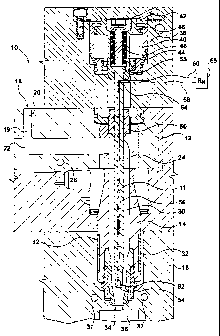
Reference is made to Figures 1 and 2, which show an injection molding
machine 10 having a valve pin 11 in accordance with a first embodiment of
the present invention. Injection molding machine 10 includes a manifold block
12, a plurality of nozzles 14 and a mold cavity block 16. The manifold block
12 may have many possible melt channel configurations. For example, as
shown in Figure 1, the manifold block 12 may include an inlet 18, and a
plurality of melt channels 19, including an inlet melt channel 20, a plurality
of
intermediate melt channels 22 downstream from the inlet melt channel 20 and
a plurality of outgoing melt channels 24 downstream from the intermediate
CA 02463498 2004-04-13
WO 03/031146 PCT/CA02/01528
4
melt channels 22. The manifold block 12 is heated, by a heater 26. Heater 26
may be any suitable type of manifold heater known in the art.
The nozzles 14 are positioned downstream from the outgoing melt
channels 24. Each nozzle 14 includes a nozzle body 28, which has a nozzle
melt channel 30 therein. The nozzle 14 is heated by a nozzle heater 32,
which may be mounted to the nozzle 14 in any way known in the art. For
example, nozzle heater 32 may surround the exterior of the nozzle body 28,
as shown in Figure 1, or alternatively, nozzle heater 32 may be embedded
within nozzle body 28. The nozzle melt channel 30 ends at a gate 34, which
is the entrance from the nozzle melt channel 30 into a mold cavity 36 in the
mold cavity block 16. Mold cavity block 16 may be cooled by a cooling fluid in
cooling channels 37.
Melt passes from a melt source (not shown), through inlet 18 in
manifold block 12, through melt channels 20, 22 and 24, through the nozzle
melt channels 30 and through gates 34 into mold cavities 36.
Valve pins 11 are positioned within the nozzle melt channels 30 to
control the flow of melt into the mold cavities 36. Valve pins 11 may be
movable within the nozzle melt channel 30, as shown, by an actuator 38.
Alternatively, valve pins 11 may be stationary within nozzle melt channel 30.
Actuator 38 may be any suitable type of actuator. For example,
actuator 38 may include a chamber 40, having a first fluid passage 42
proximate one end of the chamber 40, a second fluid passage 44 proximate
the opposing end of the chamber 40, a piston 46 in the chamber 40 and a rod
48 extending from the piston 46 to outside the chamber 40. The rod 48 may
connect the piston 46 inside the chamber 40 to the valve pin 11, using any
suitable connection means. For several reasons including ease of cleanout,
the rod 48 preferably connects to the valve pin 11 outside of any melt
channels 19 and 30, so that the melt is not permitted to seep into the
connection. The rod 48 itself may be fixedly connected to the piston 46.
A fluid, such as, for example, hydraulic oil or air, may be introduced
into the chamber 40 on one side of the piston 46 at a selected pressure
and/or removed on the opposing side of the piston 46 to move the piston 46,
(and in turn, the rod 48 and the valve pin 11 ), in a direction either towards
or
away from the gate 34. The movement of the valve pin 11 towards and away
CA 02463498 2004-04-13
WO 03/031146 PCT/CA02/01528
from the gate 34 may be, for example, to control the melt flow into the mold
cavity 36.
The valve pin 11 passes from outside the outgoing melt channel 24 into
the outgoing melt channel 24 through a mold plug 50. Mold plug 50 seals
5 around valve pin 11 to inhibit melt from escaping from outgoing melt channel
24. The mold plug 50 may further permit sliding of the valve pin 11
therethrough, so that valve pin 11 can move, as desired in melt channels 24
and/or 30. In the position shown in Figure 1, valve pin 11 is in the open
position, that is, the position in which melt flow is permitted into mold
cavity
36.
Valve pin 11 includes a valve pin body 52, which has an end 54. The
end 54 may be tapered, as shown in Figures 1 and 2, or alternatively, may
have any suitable shape, such as cylindrical. The end 54 may be used for
gating purposes, ie. for the closing of the gate 34. In the position shown in
Figure 2, the valve pin 11 is in the closed position, with the end 54 being
positioned in the gate 34, to prevent melt flow into mold cavity 36.
Valve pin 11 may further include a head 55. The head 55 may be used
to facilitate connecting the valve pin 11 to the piston 46. The head 55 may be
positioned at the end of the valve pin 11 opposed to the end 54. The head 55
may be a disc-shaped portion that has a larger diameter than that of the valve
pin body 52. The head 55 may be captured by any suitable means known in
the art, so that the valve pin 11 is removable from the rod 48.
Valve pin 11 further includes a thermocouple 56. The thermocouple 56
may be a two-wire type. For example, the thermocouple 56 may include a
first electrical conduit 58, which may be a wire 58, a second electrical
conduit
60, which may be a wire 60, and a sensing piece 62, which connects the
wires 58 and 60 at one end. The wires 58 and 60 are preferably insulated
along their length, to inhibit being heated by something other than the
sensing
piece 62. The thermocouple 56 may be of a configuration described in US
Patent No. 5,009,718 (Schmidt).
Thermocouple 56 may be embedded in valve pin body 52, as shown,
or may alternatively, may extend in an internal passage in valve pin body 52.
The sensing piece 62 may be positioned proximate the end 54 of the
valve pin body 52 to record the temperature of melt that is relatively close
to
CA 02463498 2004-04-13
WO 03/031146 PCT/CA02/01528
6
the gate 34. The term 'proximate' as used herein, indicates that the sensing
piece 62 may be near end 54 or may be in the end 54.
The wires 58 and 60 from thermocouple 56 may exit from the valve pin
body 52 outside of the nozzle melt channel 30 and manifold outgoing melt
channel 24. Thermocouple 56 exits from valve pin 11 at an exit point 64. Exit
point 64 may be at any suitable position on valve pin 11, such as, for
example, on the side of the valve pin body 52, as shown. The position of exit
point 64 should be such that the exiting wires 58 and 60 do not interfere with
the movement of valve pin 11 in melt channels 24 and 30. Thermocouple 56
may be connected to a receiving device 65 for receiving, processing,
transmitting and/or recording the measurements from thermocouple 56.
Wires 58 and 60 should be long enough between valve pin 11 and receiving
device 65, so that they do not interfere with the movement of valve pin 11.
By positioning the thermocouple 56 inside the valve pin body 52, the
thermocouple 56 can measure the temperature of the melt while it is protected
from wear from the melt flow in the nozzle melt channel 30. This is in
contrast
to valve pins having a film-type thermocouple applied thereto where
substantially all of the film-type thermocouple is exposed to the melt flow.
Reference is made to Figures 3a, 3b and 3c, which illustrate a method
in accordance with the present invention, for making valve pin 11. Reference
is made to Figure 3a. To make a valve pin 11 having a thermocouple 56, a
passage 66 may be made in valve pin body 52. Passage 66 may be cast
directly into the valve pin body 52, or may be machined into valve pin body
52. Passage 66 may be blind and may therefore end internally in valve pin
body 52 at any suitable point, such as, for example, proximate to end 54, as
shown in Figure 3a. Aperture 68 is the opening of passage 66 to the exterior
of the valve pin 11. Aperture 68 may be positioned at any suitable point on
valve pin 11. Aperture 68 may act as the exit point 64 for the wires 58 and 60
from valve pin body 52.
Referring to Figure 3b, the thermocouple 56 may be fed into passage
66 so that the sensing piece 62 is positioned at the blind end of passage 66.
Referring to Figure 3c, the passage 66 may be filled fully or partially with a
retainer 70, to hold the thermocouple 56 in place in passage 66. The retainer
70 may be thermally conductive, so that it increases the thermal conductivity
CA 02463498 2004-04-13
WO 03/031146 PCT/CA02/01528
7
between the sensing piece 72 and the melt flow surrounding the valve pin 11,
relative to an air gap that would otherwise surround the thermocouple 56 in
the passage 66. The increased thermal conductivity increases the accuracy
of the thermocouple 56 in reading the temperature of the melt flow around the
valve pin 11. After filling the passage 66 with the retainer 70, the retainer
70
may be solidified as necessary to prevent the thermocouple 56 from being
inadvertently moved in the valve pin 11 during use.
Reference is made to Figure 3d. As an alternative, valve pin body 52
may include a passage 72, which passes through end 54 of valve pin 11, so
that there is an aperture 74 on the end 54 of valve pin 11. In this
alternative,
the thermocouple 56 may pass through the aperture 74, so that the sensing
piece 62 of thermocouple 56 is flush with the surface of the valve pin at end
54. A suitable material may then be used to fill any air gap between the
sensing piece 62 in the aperture 74, so that the end 54 of the valve pin 11
has
a smooth surface.
Reference is made to Figure 4, which shows valve pin 11 in use with a
nozzle 100. Nozzle 100 is similar to nozzle 14, except that nozzle 100 may
have a nozzle body 102 with an offset nozzle melt channel 104. Valve pin 11
may pass through manifold 12, through nozzle body 102 and into nozzle melt
channel 104. Valve pin 11 may be actuated by actuator 38 or may
alternatively be stationary within nozzle melt channel 104.
Reference is made to Figure 5, which shows a valve pin 11 in use with
a nozzle 110. Nozzle 110 is similar to nozzle 14, except that nozzle 110
includes an actuator 112, which replaces actuator 38. Actuator 112 is a rack-
and-pinion type actuator, and includes a rack 114, a plurality of pinions 116,
and a plurality of valve pin holders 118. The rack 114 may move laterally
relative to the nozzles 110, along the line of direction shown by arrows A,
and
engages the pinions 116, which are mounted onto the valve pin holders 118.
The pinions 116 and the valve pin holders 118 rotate in response to the
lateral
movement of the rack 114. The valve pin 11 in this case, rotates to control
the flow of melt to the gate 34, rather than moving towards and away from the
gate 34. A rack-and-pinion actuator construction that may be used with the
valve pin 11 having the thermocouple 56 therein, is described further in US
Patent No. 4,330,258 (Gellert). It is alternatively possible for a separate
rack
CA 02463498 2004-04-13
WO 03/031146 PCT/CA02/01528
8
to be provided for each pinion. As a further alternative, it is possible for
the
rack or racks to be positioned other than laterally.
Reference is made to Figure 6, which shows a nozzle 150 with the
valve pin 11 in accordance with the present invention. Nozzle 150 is similar
to
nozzle 14, except that nozzle 150 includes a body 152 having a second
thermocouple 154 connected thereto. Thermocouple 154 may be used to
measure the temperature of some portion of the nozzle 150 itself. For
example, the thermocouple 154 may be used to measure the temperature of
the nozzle body 152 or the temperature of the nozzle heater 32.
Reference is made to Figure 7, which shows a multi-gate injection
molding machine 200. Molding machine 200 may include a mold cavity plate
202 with a plurality of mold cavities 204. Each mold cavity 204 may have a
plurality of gates 206 permitting entry of melt into mold cavity 204 from a
plurality of points. Molding machine 200 may further include manifold 12, and
a plurality of nozzles 14, whereby more than one nozzle 14 may feed melt to a
single mold cavity 204. Valve pins 11 may be included in moiaing macnine
200, to provide melt temperature information from each nozzle 14 leading to a
mold cavity 204.
Reference is made to Figures 8a, 8b and 8c, which show a co-injection
molding machine 300 with a co-injection nozzle 302. Co-injection is the
injection of different materials into a single mold cavity 303 to form, for
example, a product having several layers. Some of the layers may be made
from the same material, and some layers may be made from a different
material. Some layers may flow into the mold cavity 303 simultaneously,
while some layers may flow into the mold cavity 303 sequentially. Co
injection is used for many applications, such as preforms for soft drink
bottles.
Molding machine 300 may include a plurality of manifolds, such as
manifolds 304 and 306. Manifolds 304 and 306 receive melt from a plurality
of melt sources (not shown), and may have a plurality of melt channels
therein, which are shown at 308, 310 and 312. Each melt channel 308, 310
and 312 carries melt which forms a different layer of the final molded
product.
Co-injection nozzle 302 may include a first nozzle melt channel 314, a
second nozzle melt channel 316 and a third nozzle melt channel 318, which
receive melt from manifold melt channels 308, 310 and 312 respectively.
CA 02463498 2004-04-13
WO 03/031146 PCT/CA02/01528
9
Such a configuration is described in PCT publication no. WO00/54954 (Gellert
et al.). Nozzle melt channel 314 may be central and coherent along its length,
while melt channel 316 may be annular and may join with melt channel 314,
so that a second layer of material may be introduced into melt channel 314.
Melt channel 318 may also be annular and join melt channel 314 to introduce
a third layer of material to melt channel 314.
Valve pin 11 may be moved in melt channel 314 to permit the flow of
the materials into the melt channel 314 or to permit the flow of materials
into
the mold cavity 303. As valve pin 11 moves in melt channel 314, different
temperature information may be obtained. For example, as the valve pin 11 is
in the closed position, shown in Figure 8a, thermocouple 56 may obtain
temperature information on the melt in the mold cavity 303, and particularly
on
the material in the gate area 320 of the mold cavity 303. Such temperature
information can be useful, for example, to help control the rate of cooling of
the mold cavity. It is advantageous to control the rate of cooling, to inhibit
crystallinity development in the molded part. As the valve pin 11 moves to the
position shown in Figure 8b, the thermocouple 56 can obtain information on
the melt flow from nozzle melt channel 318. As the valve pin 11 moves to the
position shown in Figure 8c, the thermocouple 56 can obtain temperature
information on the melt in melt channel 314 received from melt channels 308
and 310.
Reference is made to Figure 9, which shows a valve pin 400. Valve
pin 400 is similar to valve pin 11, except that valve pin 400 includes a
plurality
of thermocouples 56. Thermocouples 56 may be positioned at different points
within valve pin 400, so that temperature information may be obtained on
different portions of a single melt flow, or different melt flows.
Referring to Figure 1, for example, the temperature of a nozzle, such
as the nozzle 14, typically varies over its length. Typically, the nozzle 14
is
hottest in the middle, and is cooler at the ends where it contacts the
manifold
block 12 and the mold cavity plate 16 respectively, due to their lower
temperatures. Because of the temperature variation, it may be useful to
measure the temperature of melt at different points in the nozzle melt channel
30 simultaneously. By incorporating a plurality of thermocouples 56 in the
CA 02463498 2004-04-13
WO 03/031146 PCT/CA02/01528
valve pin 400 (Figure 9), the melt temperature can be known simultaneously
at a plurality of points along the length of the nozzle melt channel 30.
Referring to Figure 9, a first thermocouple 402, and a second
thermocouple 404 may be provided in the valve pin 400. The first
5 thermocouple 402 may be positioned at or near the end of the valve pin 400,
which is shown at 406. The end 406 may be used for gating purposes, and
may cooperate with the 34 (Figure 1) to seal against melt flow into the mold
cavity 36 (Figure 1).
The second thermocouple 404 may be positioned spaced from the first
10 thermocouple 402, such as, for example, in a central portion 408 of the
valve
pin 400. The central portion 408 is the portion of the valve pin 400 that is
adapted to be positioned generally in the region of the nozzle 14 (Figure 1)
the hotter central portion of the nozzle 14, which is spaced from its two
ends,
where the nozzle 14 contacts the mold cavity plate 16 and the manifold plate
12.
The actuator 38 has been described as being a hydraulic piston-type,
and as a rack-and-pinion type. Alternatively, the actuator 38 may be an
electric rotary actuator, or an electric linear actuator, which can be
connected
to the valve pin 11.
While the above description constitutes the preferred embodiments, it
will be appreciated that the present invention is susceptible to modification
and change without departing from the fair meaning of the accompanying
claims.