Note : Les descriptions sont présentées dans la langue officielle dans laquelle elles ont été soumises.
CA 02465041 2004-04-22
TITLE
SUSPENSION AND SILL SYSTEM FOR SLIDING MEMBERS
INTRODUCTION
This invention relates to a suspension and sill
system for sliding members and, more particularly, to a
suspension and sill assembly system for heavy duty
sliding doors or panels which doors or panels may be
exposed to exterior weather conditions.
BACKGROUND OF THE INVENTION
Exterior sliding doors or panels which are
opened and closed by sliding within a groove and which
are maintained in their generally vertical position
during the sliding movement are ubiquitous in residential
and commercial construction. However, disadvantages in
the use and installation of such panels are well known.
First, if the sliding members are heavy, hanging such
CA 02465041 2004-04-22
- 2 -
members is difficult and two or more specialized
installers may be required. Second, continued and proper
adjustment of the sliding panels is important for proper
operation of the panels or doors and, again, skilled
labor may not be readily available. Third, existing
sliding members generally have their entire weight acting
on bearings located on the bottom of the door which run
on a rail. The rail is raised from the surface of the
exterior and interior floors which causes access problems
for carts and disabled users. The bearings, being on the
bottom of the door, attract water and other debris which
contacts the door and falls downwardly into the bearing
area over time. The debris may enter the bearings,
prohibit smooth movement of the doors and cause premature
wear. In an effort to prevent this contamination,
friction brushes are often used which, in turn, interfere
with the smooth movement of the sliding members. Fourth,
the weight of such doors may act in an unbalanced way on
the bearings if they are not precisely positioned. Thus,
one set of bearings may receive more loading than a
second set of bearings which affects the operation of the
doors and the bearing life. Finally, subsequent service
to the sliding members after installation typically
requires a number of service personal to raise the doors
off their track for cleaning, item replacement and the
CA 02465041 2011-07-05
3 -
like. Thereafter, the panel members will require
installation and adjustment. This is unnecessarily
expensive, time consuming and inconvenient for the user.
SUMMARY OF THE INVENTION
According to one aspect of the invention there
is provided suspension system and sliding panel assembly
comprising at least one vertically positioned sliding
panel, said sliding panel having an upper frame and a
bottom, a bearing assembly connected to said upper frame
of said sliding panel, a bottom guide for said sliding
panel connected to said bottom of said sliding panel,
said bearing assembly including at least two sets of
bearings, each of said sets of bearings comprising a pair
of wheels mounted perpendicularly to the plane of said
panel and each of said wheels being operable to move in a
respective concave track, a hanger connected and
centrally hung between each of said pair of wheels, said
hanger running parallel to the plane of said sliding
panel a distance at least substantially as long as the
length between said sets of bearings, said hanger being
received within a wedge, said wedge extending for a
distance at least as long as said hanger, said wedge
being operably mounted between said panel and said
bearing assembly, either of said wedge or said bearing
assembly being movable relative to the other of said
wedge and bearing assembly with said other of said wedge
CA 02465041 2011-07-05
4 -
or hanger being stationary relative to said panel and
being operably attached to said panel, said sliding panel
being hung from said hanger such that the weight of said
panel acts principally through said hanger and applies
substantially equal loading to each of said pair of
wheels, said wheels having rounded convex circumferences
which are complementary to and which run within said
concave track.
According to a further aspect of the invention
there is provided a sliding panel and bearing assembly
for installation within an upper bracket of a panel frame
and a lower drain tube of said panel frame, said sliding
panel having a top and a bottom, said sliding panel and
bearing assembly comprising an upper bearing connected to
said top of said sliding panel and movable within said
upper bracket and a lower guide member on said bottom of
said panel which guide member is movable within said
lower drain tube, said upper bearing comprising at least
two sets of bearings, each of said sets of bearings
including a pair of rotatable wheels, each of said wheels
having a convex circumference which convex circumference
is complementary to and moves within respective concave
guide paths located on opposite sides of and within said
upper bracket and a hanger extending downwardly from said
sets of bearings and between said pair of rotatable
wheels, said hanger extending on the top of said panel a
length at least substantially as long as the distance
between said sets of bearings, said panel having a weight
which acts principally downwardly through said-hanger and
which exerts substantially identical forces on each of
said wheels on opposite sides of said hanger, a wedge
member operably installed between said bearing assembly
CA 02465041 2011-07-05
-
and said sliding panel, said wedge member being movable
relative to one of said bearing assembly and said sliding
panel, the other of said bearing assembly and said
sliding panel being stationary relative to said wedge
5 member and being operably attached to said panel, said
hanger of said bearing assembly being received in said
wedge member, said wedge member extending at least as
long as said hanger.
BRIEF DESCRIPTION OF THE SEVERAL VIEWS OF THE DRAWINGS
Specific embodiments of the invention will now
be described, by way of example only, with the use of
drawings in which:
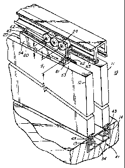
FIG. 1 is a diagrammatic isometric and cutaway
view of two(2) adjacent sliding doors moving within
adjacent drain tubes and which sliding doors incorporate
the teachings of the present invention; and
FIG. 2 is a diagrammatic end view of the
sliding doors particularly showing the bearing mounting
and the sill construction in which the sliding doors are
guided according to a further aspect of the invention.
CA 02465041 2004-04-22
6 -
DESCRIPTION OF SPECIFIC EMBODIMENT
Referring now to the drawings, a set of sliding
doors, in this case, two(2) such doors 11, 12 is
generally shown at 10 in Figure 1. The first and second
doors 11, 12, respectively, move within respective guide
strips 13, 14 and are each hung from a pair of upper
hanging assemblies, one such hanging assembly being
generally illustrated in detail at 20. A lower guide or
sill assembly is generally illustrated at 21 in Figure 2,
it being understood that the upper hanging assemblies 20
and the lower guide or sill assembly 21 are the same for
each of the sliding doors 11, 12.
A support bracket conveniently in the form of
an aluminum extrusion 22 is mounted in the frame of the
house or other structure (not shown). The support
bracket 22 includes two(2) bearing guide paths 23 to
allow the rotating bearings 24 of the bearing assembly 20
to move therein as will be described. The support
bracket 22 also conveniently includes brush housings 30
which hold removable mohair brushes 31 used to provide a
brushing action against the top frame member 32 of door
11 and thereby to prevent the ingress of water and debris
and to remove loose foreign material from the door 11
CA 02465041 2004-04-22
- 7 -
during the sliding operation.
A second extrusion, conveniently a plastic
drain tube 33, is similarly mounted in the frame of the
house or other structure and forms the principal member
of the sill assembly 21. The drain tube 33 contains side
drain holes 44 and/or bottom drain holes 50 to allow the
drainage of moisture and other debris to the outside
environment. The drain tube 33 also allows for the
entrance and retention of several shims or ribs 34. The
shims 34 (Fig. 2) extend perpendicular to the
longitudinal axis of the drain tube 33 and are relatively
narrow. The shims 34 provide support for the guide
strips 40 which are removably mounted on the shims 34 and
within the drain tube 33. The guide strips 40 also
contain brush housings 41 which allow the entry of
removable mohair brushes 42. The brushes 42 bear on a
guide or key 43 which is connected to the lower portion
of the door 11 and which guide or key 43 provides a
degree of stability during the sliding movement of the
panel members 11, 12. The guide 43 extends substantially
the entire length of the bottom of the door 11 and may
take the form of a T-section which is bolted to the
bottom of the door 11 at several different locations to
ensure connection integrity. It will be noted that the
CA 02465041 2004-04-22
g _
upper surface of the drain tube 33 may conveniently be
level with both the interior and exterior floor surfaces
66, 67 thereby allowing carts, wheelchairs and the like
to easily move along the floor surfaces 66, 67 and over
the top of the drain tube 66 without difficulty although
the upper surface may also be raised or lowered relative
to the floor surfaces if desired.
The bearing assembly 25 includes the rotatable
bearings 24 which are conveniently heavy duty and made
from a TEFLON material in order to reduce the friction
between the bearings 24 and the bearing guide paths 23
when the bearings 24 are moving within the guide paths
23. The bearings 24 conveniently number three (3) and
rotate about respective axes 51. Bearings 24 are
connected on each side of a hanger 52 which extends
downwardly and centrally between the bearings 24 thereby
to reduce or eliminate any moment acting on the bearings
24 by the hanging members 11, 12 which are each connected
to the hanger 52 as will be described.
Hanger 52 terminates in an enlarged female
member 53 which is mounted for reciprocal and
longitudinal movement within a wedge member 54. The
hanger 52 extends downwardly from the forward most
CA 02465041 2004-04-22
9 -
bearing 24 as viewed in Figure 1 a distance "dl" which
distance "dl" is longer than the distance "d2" from the
rearward one of the bearings 24 as also seen in Figure 1.
The slope between the two distances dl, d2 matches the
slope of a wedge member 54 in which the female member 53
moves. Wedge member 54 is connected to an anchor plate
60 (Figures 1 and 2) which anchor plate 60 is mounted to
the top of the door 11 and which has bolts 55 extending
there through. Wedge member 54 therefore moves with door
11 and anchor plate 60 and remains stationary relative to
the door 11 and anchor plate 60.
A threaded hole 61 extends through the female
member 53 of hanger 52 and a threaded bolt 62 is
threadedly connected through hole 61. A socket 64 in the
end of the threaded bolt 62 allows the entry of a
complementary matching member on the end of a tool (not
shown) which is used to rotate the bolt 62. The bolt 62
is held by a collar 63 mounted for stationary position
within wedge member 54 which collar 63 allows the bolt 62
to rotate freely within the threaded hole 61 of wedge
member 54 while not moving the bolt 62 longitudinally and
thereby drawing the hanger assembly 25 along the wedge
member 54 which, because of the connection between the
wedge member 54 and anchor plate 60 to the door 11,
CA 02465041 2004-04-22
- 10 -
allows the panel member or door 11 to be easily moved
upwardly and downwardly relative to the door bearing
assembly 25 and the support bracket 22 as the
installation may require in order that the door 11 hangs
cleanly and moves freely.
A recess 65 is provided in the support bracket
or aluminum extrusion 22 at the end of the bracket 22
mounted in the frame of the moving panels 11, 12 (Figure
1). It will be understood that a further and second
recess 64 is provided at the opposite end of the support
bracket 22 which is not illustrated in Figure 1. The
recess 65 is formed by cutting away material previously
forming the bearing guide paths 23 formed on either side
of the longitudinal axis of the bracket 22. By removing
the guide path material to form the recess 65, the
bearing assembly 25 is easily inserted into the support
bracket 22 and the bearings 24 can then move freely on
the bearing guide paths 23. To prevent the bearings 24
from moving into the recess 65 during sliding movement
and operation of the door 11, the wedge member 54 and
anchor plate 60 are mounted to the door 11 at a position
where, with the door 11 in its limiting positions of
movement within lower drain tube 33 and upper support
bracket 22, the bearings 24 remain a distance away from
CA 02465041 2004-04-22
- 11 -
the recess 65 thereby avoiding any unnecessary stress in
the bearing guide paths 23 adjacent the recess 65 and
thereby avoiding the recess 65 entirely.
OPERATION
In operation, it will be assumed that the upper
support bracket 22 and the lower drain tube 33 have been
installed in the frame of the structure into which the
sliding panel or door assembly 10 is to be installed and
that it is now intended to install the panel or door
assembly 10 (Figure 1).
The anchor plates 60, one for each of the
bearing assemblies 25, which bearing assemblies 25 are
mounted at opposite ends of each panel or door 11, are
mounted to the top of each of the doors 11, 12 as seen in
Figure 1 and the key member 43 is attached to the bottom
of the doors 11, 12 again by bolting the key member 43 to
the door 11. The wedge members 54 are then connected to
the anchor plates 60 by bolts 71 extending into the
anchor plates 60. One wedge member 54 is mounted to each
of the anchor plates 60; that is, one anchor plate 60 and
one wedge member 54 are mounted to each end of each door
11, 12.
CA 02465041 2004-04-22
- 12 -
The lower guide strips 40 will be placed into
position within drain tube 33 and will rest on the shims
34, the shims 34 being placed perpendicular to the
longitudinal axis of the drain tube 33 and spaced
intermittently along its length.
The doors 11, 12 will then be manually moved
into their general installation position by placing the
key 43 on the bottom of the door 11 into the guide strip
40 and allowing the door 11 to remain substantially
vertically in its resting position on the drain tube 33.
The top of the door 11 will be inserted into and retained
by the sides of the support bracket 22 to prevent the
door 11 from moving sidewardly and falling from its
temporary and upright position.
An installer will then begin the final hanging.
The installer will insert a bearing assembly 25 into each
of the wedge assemblies 54 by inserting the rotating
bearings 24 into the guide paths 23 through the recess 64
(Figure 1). He will then move the door 11 until the
hanger 52 and male member 53 are aligned with the recess
72 in the wedge member 54 (Figure 3A) and the bolt 62 is
rotated with the installation tool (not shown) which
rotates the bolt 62 through its end socket 64 until the
CA 02465041 2004-04-22
- 13 -
wedge assembly is fully engaged. A similar procedure
will take place between the second bearing assembly 25
and the second wedge member 54 at the opposite end of the
door 11. The installer will then raise or lower the door
11 relative to the guide paths 23 by appropriately
rotating the bolt 62 at each end of the door 11 so that
the key 43 reciprocates freely within the guide strips 40
with the mohair brushes 42 suitably brushing the key 43
as the movement of the door 11 takes place and so that
the door 11 is suitably level within the upper extrusion
22 and so that the vertical ends 73 of the door 11 match
the vertical sides (not shown) of the door frame.
It will be appreciated that the bearings 24 act
on either side of the longitudinal axis 70 of the upper
support bracket 22 and that the door 11 hangs vertically
from the hanger 52 which is connected to the bearings 24.
Thus, the weight of the door 11 acts generally vertically
downwardly and generates little if any moment on the
bearings 24 and bearing assembly 25. The key 43 thereby
also moves freely within the guide strips 40 and allows
the mohair brushes 40 to brush debris and foreign
material off the key 43 which debris is disposed of
through the bottom and side drain holes 50, 44,
respectively, in the drain tube 33. The key 43 also
CA 02465041 2004-04-22
- 14 -
serves to block the egress of wind and water driven from
the outside environment. Any such wind, water or debris
will fall into the guide strips 40, thence to the guide
tube 33 and out to the outside via drain tubes 44, 50.
The use of the wedge member 54 to move the door
11 upwards and downwards will allow a single installer to
provide the finished door installation in which the door
11 may be centered and raised or lowered as necessary so
the loading of the door 11 will fall on the bearings 24
of the bearing assembly 25 and so that the door 11 may be
appropriated fitted within the door frame to provide a
close matching fit with the door frame. The panel or
door members 11, 12 may also be easily raised relative to
the guide tube 33 by a user using the described tool to
rotate bolt 62 and thereby raise the panel members 11, 12
relative to the guide tube 33. If the user intends to
clean the guide tube 33 and drain tubes 40 of the sill
assembly 21, it is convenient to do so without the
necessity of removing the heavy door or panels 11, 12.
All the members making up the sill assembly 21 can be
easily replaced if necessary.
Many modifications will readily occur to those
skilled in the art to which the invention relates. For
CA 02465041 2004-04-22
- 15 -
example, the use of relative movement between the wedge
member 54 and the bearing assembly 25 so as to lift and
lower the door 11 relative to the extrusion 22 may
suitably be modified by allowing the bearing assembly 25
to remain stationary relative to the door 11 and by
moving the wedge member 54 relative to the door 11 and
bearing assembly 25. All that is needed is relative
movement between the bearing assembly 25 and the wedge
member 54 in order to provide the necessary adjustment.
Likewise, while it is apparent that the use of heavy
sliding doors, used in exteriorly exposed position, will
most often make use of the invention, it is intended to
cover sliding panel members as well.
It is further contemplated that, of course,
portions of the sill assembly can be raised if desired
such that the sill assembly may project above the
surfaces of the exterior and interior floors.
Many further modifications will readily occur
to those skilled in the art to which the invention
relates and the particular embodiments herein described
should be taken as illustrative of the invention only and
not as limiting its scope as defined in accordance with
the accompanying claims.