Sélection de la langue

Search

Sommaire du brevet 2466162 

Énoncé de désistement de responsabilité concernant l'information provenant de tiers

Une partie des informations de ce site Web a été fournie par des sources externes. Le gouvernement du Canada n'assume aucune responsabilité concernant la précision, l'actualité ou la fiabilité des informations fournies par les sources externes. Les utilisateurs qui désirent employer cette information devraient consulter directement la source des informations. Le contenu fourni par les sources externes n'est pas assujetti aux exigences sur les langues officielles, la protection des renseignements personnels et l'accessibilité.

Disponibilité de l'Abrégé et des Revendications

L'apparition de différences dans le texte et l'image des Revendications et de l'Abrégé dépend du moment auquel le document est publié. Les textes des Revendications et de l'Abrégé sont affichés :

  • lorsque la demande peut être examinée par le public;
  • lorsque le brevet est émis (délivrance).
(12) Brevet: (11) CA 2466162
(54) Titre français: ALIMENTATION ELECTRIQUE EN COURANT ALTERNATIF ET CONTINU PAR BATTERIE A DOUBLE ENTREE
(54) Titre anglais: DUAL INPUT AC/DC/BATTERY OPERATED POWER SUPPLY
Statut: Périmé et au-delà du délai pour l’annulation
Données bibliographiques
(51) Classification internationale des brevets (CIB):
  • H02M 01/10 (2006.01)
  • G06F 01/26 (2006.01)
  • H02J 07/34 (2006.01)
  • H02J 09/06 (2006.01)
(72) Inventeurs :
  • DOSS, JEFFERY S. (Etats-Unis d'Amérique)
  • DUBOSE, RICHARD GARRISON (Etats-Unis d'Amérique)
  • PIATETSKY, ALEXEI A. (Allemagne)
  • MACDONALD, GILBERT (Etats-Unis d'Amérique)
  • LORD, CHARLES (Etats-Unis d'Amérique)
  • SMITH, SCOTT (Etats-Unis d'Amérique)
(73) Titulaires :
  • IGO, INC.
(71) Demandeurs :
  • IGO, INC. (Etats-Unis d'Amérique)
(74) Agent: GOWLING WLG (CANADA) LLP
(74) Co-agent:
(45) Délivré: 2007-07-24
(86) Date de dépôt PCT: 2002-10-30
(87) Mise à la disponibilité du public: 2003-05-08
Requête d'examen: 2004-05-20
Licence disponible: S.O.
Cédé au domaine public: S.O.
(25) Langue des documents déposés: Anglais

Traité de coopération en matière de brevets (PCT): Oui
(86) Numéro de la demande PCT: PCT/US2002/034766
(87) Numéro de publication internationale PCT: US2002034766
(85) Entrée nationale: 2004-04-30

(30) Données de priorité de la demande:
Numéro de la demande Pays / territoire Date
10/005,961 (Etats-Unis d'Amérique) 2001-12-03
10/159,910 (Etats-Unis d'Amérique) 2002-05-31
60/335,785 (Etats-Unis d'Amérique) 2001-10-31

Abrégés

Abrégé français

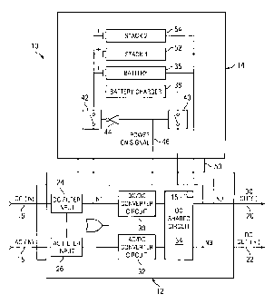
Convertisseur de courant (10) assisté par une batterie à double entrée et alimentant en tension de courant continu régulé un dispositif mobile connecté utilisateur tel qu'un ordinateur personnel ou un téléphone cellulaire. Ce convertisseur de courant (10) comprend un circuit d'alimentation électrique (12) et un circuit séparé détachable d'accumulation de courant consistant en un bloc-batterie (14) possédant une batterie rechargeable (36). Cette alimentation électrique (12) est conçue pour alimenter une paire de bornes de sortie respectives en une paire de tensions de sortie de courant continu régulé de potentiels contraires. Ces tensions de sortie, sont, de préférence, dérivées de deux tensions d'entrée externes: une tension d'entrée de courant alternatif et une tension d'entrée de courant continu. Si on supprime temporairement les deux tensions d'entrée externes, le bloc-batterie (14) servira avantageusement de source de remplacement de courant continu d'entrée, ce qui permettra à l'alimentation électrique (12) d'alimenter sans interruption le dispositif mobile connecté utilisateur en une même tension de sortie de courant continu régulé. De plus, une fois qu'on a rétabli l'une ou l'autre des tensions d'entrée externes, le bloc-batterie (14) se branche automatiquement sur la borne de sortie de l'alimentation électrique (12) au niveau d'un noeud afin de se recharger automatiquement.


Abrégé anglais


A dual input battery assisted power converter (10) which provides a
continuous, regulated DC voltage output to a user-connected mobile device,
such as, a laptop computer or a cell phone, for example. The power converter
(10) comprises a power supply circuit (12) and a separate, detachable power
storage circuit comprising a battery pack (14) having a re-chargeable battery
(36). The power supply (12) is adapted to deliver a pair of regulated DC
output voltages, of opposite voltage potentials, to a pair of respective
output terminals. Preferably these output voltages are derived from two
external input voltages: an AC input voltage and a DC input voltage.
Advantageously, if both of the external input voltages are temporarily
removed, the battery pack (14) will advantageously serve as a substitute DC
input power source, thereby allowing the power supply (12) to deliver the same
regulated DC output voltage to the user-connected mobile device without
interruption. Moreover, once either of the external input voltages are again
re-established, the battery pack (14) automatically taps the output terminal
of the power supply (12) at a node to recharge the battery pack (14).

Revendications

Note : Les revendications sont présentées dans la langue officielle dans laquelle elles ont été soumises.


WHAT IS CLAIMED IS:
1. A power converter, comprising:
a power supply circuit providing a regulated DC output voltage
and having first and second circuits, said power supply circuit receiving an
AC
input voltage and a DC input voltage at respective said first and second
circuits and providing, in response thereto, a DC output voltage at a first
node;
and
a storage circuit selectively coupled to said power supply
circuit, said storage circuit storing a secondary DC input voltage,
wherein said storage circuit delivers said secondary DC input voltage to a
said
power supply circuit whenever said AC and DC input voltages are temporarily
removed.
2. The power converter of Claim 1 wherein said storage circuit
includes a battery charger and a re-chargeable battery, said battery charger
being coupled to the first node of said power supply circuit, charging said re-
chargeable battery via a portion said of said regulated DC output voltage.
3. The power converter of Claim 1 wherein said storage circuit
energizes said power supply circuit whenever each input voltage is not
provided to said power supply circuit.
4. The power converter of Claim 2 wherein said storage circuit
further comprises a first switch and a second switch, said battery charger,
responsive to said first and second switches charging said re-chargeable
battery.
-9-

5. The power converter of Claim 4 wherein said re-chargeable
battery, responsive to said second switch being closed and said first switch
being opened by said power supply circuit, providing a DC input voltage to
one said circuit.
6. The power converter of Claim 5 wherein said storage circuit
includes an inverter gate, said inverter gate being coupled to and controlling
said first and second switches.
7. The power converter of Claim 1 wherein said first circuit
comprises a AC-to-DC converter, wherein said AC-to-DC converter is adapted
to provide a DC output voltage of between 15VDC and 24VDC.
8. The power converter of Claim 7 wherein said second circuit
comprises a DC-to-DC boost converter, wherein said DC-to-DC boost
converter is adapted to provide a DC output voltage of between 15VDC and
24VDC.
9. The power converter of Claim 1 further comprising a third
circuit, said third circuit, in response to said output voltages of said first
and
second circuits, providing a programmable DC output voltage to a node as a
function of a detachable programming key.
10. The power converter of Claim 1 wherein said storage circuit
comprises a battery back having a re-chargeable battery, said power supply
circuit providing said regulated DC output voltage in response to receiving a
charge voltage from said re-chargeable battery.
-10-

11. The power converter of Claim 1 wherein said power supply
circuit is coupled to said storage circuit at a plurality of different nodes
via a
common connector.
12. The power converter of Claim 1 wherein said power supply
circuit is adapted to provide a pair of regulated DC output voltages of
between
5VDC and 24VDC.
13. The power converter of Claim 1 wherein said power supply
circuit is adapted to operate in a direct power mode whenever either said AC
and DC input voltages is provided to said first and second circuits.
14. The power converter of Claim 1 wherein said power supply
circuit is adapted to operate in a battery mode whenever said AC and DC input
voltages are not sensed by said first and second circuits.
15. The power converter of Claim 1 wherein said storage circuit is
configured to incorporate a plurality of stacked batteries.
16. A method of operating a power converter the method
comprising the steps of:
generating a DC output voltage responsive to an AC or DC
input voltage using a power converter; and
delivering a back-up DC input voltage to said power converter
whenever said AC and DC input voltages are removed therefrom and
generating said DC output voltage in response thereto.
17. The method of Claim 16 wherein a storage circuit including a
re-chargeable battery provides said back-up DC input voltage.
-11-

18. The method of Claim 17 wherein a portion of said DC output
voltage is provided to said storage circuit to recharge said re-chargeable
battery when either said AC or DC input voltage is provided to said power
converter.
19. The method of Claim 17 wherein said power converter includes
an AC to DC converter and a DC to DC converter.
20. The method of Claim 16 wherein said attaching step further
includes tapping said power converter at a plurality of nodes using a common
connector.
-12-

Description

Note : Les descriptions sont présentées dans la langue officielle dans laquelle elles ont été soumises.


CA 02466162 2006-10-04
w0 03/tl38980 PcT/USO2M766
DYJAY., INPUT AC/DC/ BATTERY OPERATED
POWER SUPPLY
TI:CHNYC,AL p'MD
The presont invention geaorally rcletes to the field of powcr
converters, and, more particularly, to a portable, dual input AC and DC to
programmable DC output power conv arter.
BACKGROXJND OpI'HE INVENTION
As PC notCbooks, PDAs, cell phones and tbe like, continue to grow in
popularity, so too does the need for more low eost, compact, power aWliee to
power these devic,es. Today, mpst m=ffacturers of mobile devices typically
Include plug-in power adapters along with these mobile devices to help
faoilitate their customers' power supply needs.
However, thera exists a need for a power coaverter that resolves the
system manageanent problems as oeiated with csrrying all of the differettt
powar supply components neoessary to power a wide variety of mobile or
portable devices. Moreover, saoh a power converter would sdvantageously
encaunpass serving tlie power supply needs of sevaral different mobile devices
by sapplying a regnlated DC output voltagc, reaponsive to either an extemal
AC or external DC input voltW Also, such a power converter would have
power atoring capabilities wbioh allow the power converter to deliver a

CA 02466162 2004-04-30
WO 03/038980 PCT/US02/34766
constant uninterrupted DC output voltage to a user-connected mobile device
whenever the external input voltages are momentarily cut off.
SUMMARY OF THE INVENTION
The present invention achieves technical advantages as a power
converter delivering a constant, regulated DC output voltage that may be
derived distinctly from two separate external input voltages, an AC input
voltage or a DC input voltage, and in addition, from a separate, detachable
battery pack. The detachable battery pack advantageously allows the power
converter to automatically and continuously deliver the regulated DC voltage
to the mobile device whenever each external input voltage is unreliable or is
temporarily removed. Additionally, the power converter also utilizes a portion
of the regulated DC output voltage to conveniently recharge the battery pack
during normal operation.
In one embodiment, the present invention is a power converter
comprising a power supply circuit and a selectively removable storage circuit.
The power supply circuit includes a pair of input filter circuits, each
adapted to
filter respective AC and DC input voltages provided to the power supply
circuit and providing a pair of filtered output voltages. The power supply
circuit also comprises a DC-to-DC converter and an AC-to-DC converter,
each providing a DC voltage output. The power supply also further comprises
a shared DC circuit receivingly coupled to the respective DC outputs of the
DC-to-DC converter and the AC-to-DC converter. The shared DC circuit
provides two regulated DC output voltages, of opposite polarities, at two
respective output terminals thereof. The shared DC circuit is also adapted to
allow users to selectively program the regulated output voltage, via a
programmable key, to conveniently match the voltage and current
specifications of their mobile devices.
-2-

CA 02466162 2004-04-30
WO 03/038980 PCT/US02/34766
The detachable battery pack comprises a re-chargeable battery, a
battery charger for delivering a charge current to the re-chargeable battery,
and
a switching circuit comprising a pair of switches and an inverter gate for
controlling the charging function of the battery pack. The battery pack is
adapted to tap the output terminal of the power supply circuit during normal
operation via a common connector plug for recharging. Advantageously, the
battery pack can serve as a secondary source of DC input power, in turn,
allowing the power supply of the power converter to continuously deliver
power to a user-connected device even if each external input voltage is
temporarily interrupted or removed.
BRIEF DESCRIPTION OF THE DRAWINGS
Advantages of the invention and the specific embodiments will be
understood by those of ordinary skill in the art by reference to the following
detailed description of preferred embodiments taken in conjunction with the
drawings, in which:
Figure 1 shows an AC/DC input power converter having a detachable
battery pack coupled thereto in accordance with an exemplary embodiment of
the present invention.
Figure 2 shows an AC/DC input power converter wherein the
detachable back includes multiple stackable rechargeable batteries.
-3-

CA 02466162 2004-04-30
WO 03/038980 PCT/US02/34766
DETAILED DESCRIPTION OF A PREFERRED EMBODIMENT
The invention is a multiple input power converter 10 that can be
operated from any one of three mutually exclusive and external input power
sources: a DC input, an AC input, or a separate, removable battery pack 14.
The power converter 10 can generate and deliver a regulated DC voltage
output to variety of, user-connected mobile devices, such as, laptop
computers,
cell phones, or PDAs, for example. However, if both of the external AC and
DC input voltages are accidentally or intentionally interrupted or removed
from converter 10, then the battery pack 14 will serve as a secondary source
of
input power to power the power converter 12 to deliver an uninterrupted
regulated DC voltage. Moreover, the power converter 10 will charge the
battery pack 14 with a portion of the same regulated DC output voltage during
normal operation so that battery power is available if needed.
In Figure 1 there is shown the dual input AC/DC power converter 10
comprising the power supply 12 with the physically detachable battery pack
14 coupled thereto in accordance with an exemplary embodiment of the
present invention. The power supply 12 includes two input terminals 16 and
18 for receiving the external DC input voltage and the AC input voltage,
respectively. The DC input voltage is preferably an external DC voltage,
namely, derived from a source such as an auto cigarette lighter plug, or an
airline EMPOWER DC plug, and, having a voltage ranging between 5VDC
and 15VDC. Likewise, the AC input is preferably an external AC voltage
derived from a source such as that found in most homes and business
environments, ranging between 112VAC and 230VAC. In a preferred
embodiment, the power supply 12 delivers two, regulated DC voltages, at
output terminal 22, to a user-connected mobile device coupled thereat.
In one embodiment, the power supply 12 includes a pair of noise
filtering circuits 24 and 26 for filtering each respective input voltage
arriving
at input terminals 16 and 18. The power supply 12 also includes a DC-to-DC
-4-

CA 02466162 2006-10-04
WO 03N38990 PG'IYU802134966
oonvertw circuit 30 which staps up de filtered DC voltage to a voltage of
betWeen 15 volts aud 24 volts DC and tbereafter psstes it to a alued DC
eirauit 34. Similarly, the power sapply 12 includes aa AC=to-DC coaverter
cuouit 32 that aoavextt tlLe ffibe+ed AC voltage to a DC sigqal of between
1 Svotts and 24volts. Tbe output of tlw AC-to~DC converter 32 is also iaputted
to the shared DC circuit 34. The voltages exitinM the shared DC cireuit 34,
via
terminals 20 and 22, comprise a pair of regulated DC output voltages that
users may use to power a variety of difl'erent user-coanectod mobile
device(s).
Moreovct, users of the pc+eeent invention are able to amtrol the magnitude of
the regulated DC volts,8e output, n weA aa, the current output via a
separately
detas,hable progxaaming key 15. For a more deWled description of the shared
DC circuit 34 and the programming key 15, reference is made to U.S. Patent
6,643,158 issued November 4, 2003.
The power oonverter 10 also eomprlses the aeparate, detscheble battery
pack 14, tapping the power supply 12 at respective nodes NI, N2 and N3 via
connector plug 50. The battery pack 14 compr'sses a re-cbargeable battery 36,
a batfieay oharpr 38, and a awitcbing efreuit eanqwising a first awitch 40, a
second switcb 42, and an inverter gate 44.
The proaent iavention may be configared to operate in one of two
ditYbrent operatiqg modes: grat, a direat power mode wherein the power
supply 12 gmterates the regulated DC output voltage by deriving bW power
from either of the erctmnal input voltages provided to mpective inpuc
terminals 16 and 18; and second, a battery mode, whom the power supply 12
provides a Siou'lariy regutared DC output voltage whioh is a]bematively
derived from the battary 36 of the romovable battery pack 14. Preferably, the
preaent imvealtion autanaticafly operates in the battery mode whm both of the
-5-

CA 02466162 2004-04-30
WO 03/038980 PCT/US02/34766
external input voltages is momentarily interrupted or removed from power
supply 12.
In the direct power mode, the physically attached battery pack 14 is
electrically connected to the power supply 12 via node N3, which also feeds
the output terminal 22. The battery pack 14 includes the first switch 40 and
the second switch 42 with the inverter gate 44 coupled therebetween and with
each operating initially from a normally open position, as shown. The battery
pack 14 also includes the battery charger 38 and the re-chargeable battery 36.
In operation, when either filter circuit 24 or 26 senses a received DC or
AC voltage, respectively, it generates a power-on signal on line 46 which is
sensed by the inverter gate 44. The power-on signal on line 46 triggers the
first switch 40 to close. This same power-on signal 46 is inverted by the
inverter gate 44 and received by the second switch 42 causing it to remain in
the normally open position. Once the first switch 40 is closed, a portion of
the
regulated DC output voltage provided at node N3 is passed to the battery
charger 38 by switch 40. Once energized, the battery charger 38 passes a
charge current to the positive electrode of the re-chargeable battery 36 for
charging the same. Moreover, since the second switch 42 remains in the
normally open position, switch 42 prevents the re-chargeable battery from
feeding a battery voltage to node N1, thereby preventing the power supply 12
from receiving additional DC input power.
Hence, in the direct power mode, the present invention delivers the
regulated DC output voltage, to both the mobile device at terminal 22 and to
the battery pack 14. Advantageously, users of the present invention are spared
the trouble of purchasing a separate battery pack charger to charge the
battery
pack 14.
In the battery mode, i.e. no input AC or DC power being provided to
power supply 12, the battery pack 14 automatically functions as a secondary
-6-

CA 02466162 2004-04-30
WO 03/038980 PCT/US02/34766
DC input power source. Here, no power-on signal is asserted on line 46 by the
power supply 12. As such, the first switch 40 remains in the normally open
position, and inverter gate 44 now triggers the second switch 42 to transition
from its normally open position to a closed position. As a result, the second
switch 42 electrically couples node Nl of the power supply 12 to the positive
terminal of the re-chargeable battery 36. Moreover, when the second switch
42 is closed, the re-chargeable battery 36 feeds a DC voltage of between 5
volts and 24 volts to node N1. This input battery voltage at node N1 feeds the
input of the DC-to-DC converter 30, which in turn generates a stepped up DC
voltage in response thereto and feeds it to the input of the DC shared circuit
34. The shared DC circuit 34 then generates and delivers two regulated DC
voltages of between 5 volts and 24 volts, via output terminals 20 and 22, to
the
user's mobile devices connected thereto. Thus, the battery pack 14
advantageously serves as an alternate DC input source that continually
provides a DC input voltage to the power supply 12 even if each external input
voltage at respective terminals 16 and 18 are temporarily suspended or
removed.
The power supply 12 automatically reverts back to operating in the
direct power mode whenever either external AC or DC input voltage is re-
established to terminals 16 and 18. In reverting back to its direct power
mode,
the power supply 12 will again generate an internal power on signal on line 46
causing the first switch 40 to close, and switch 42 to open, thereby causing
the
battery charger 38 to charge the re-chargeable battery 36. As previously
described this same power-on signal 46 is inverted by the inverter gate 44
such
that the second switch 42 in its normally open position. This effectively
disconnects the positive terminal of the re-chargeable battery 36 from node
N1, thereby, effectively cutting off battery power from being delivered to the
power supply 12.
-7-

CA 02466162 2004-04-30
WO 03/038980 PCT/US02/34766
Preferably, the inverter gate 44, which is coupled between switches 40
and 42, ensures that each switch is operating in the opposite state of the
other.
That is, the inverter gate 44 properly deactivates the battery pack 14 to
ensure
that the power supply 12 is not receiving input power from all three external
power sources, simultaneously.
In alternative embodiments, the battery charger 38 has characteristics
to match both the chemistry of the re-chargeable battery 36 such that the
battery pack 14 may be comprised of multiple, stacked re-chargeable batteries
52 and 54. As shown in Figure 2, these additional re-chargeable batteries may
be adapted to advantageously provide the power supply 12 with added power
storing capabilities.
The numerous innovative teachings of the present applications will be
described with particular reference to the presently preferred exemplary
embodiments. However, it should be understood that this class of
embodiments provides only a few examples of the many advantageous uses
and innovative teachings herein. In general, statements made in the
specification of the present application do not necessarily delimit any of the
various claimed inventions. Moreover, some statements may apply to some
inventive features, but not to others.
-8-

Dessin représentatif
Une figure unique qui représente un dessin illustrant l'invention.
États administratifs

2024-08-01 : Dans le cadre de la transition vers les Brevets de nouvelle génération (BNG), la base de données sur les brevets canadiens (BDBC) contient désormais un Historique d'événement plus détaillé, qui reproduit le Journal des événements de notre nouvelle solution interne.

Veuillez noter que les événements débutant par « Inactive : » se réfèrent à des événements qui ne sont plus utilisés dans notre nouvelle solution interne.

Pour une meilleure compréhension de l'état de la demande ou brevet qui figure sur cette page, la rubrique Mise en garde , et les descriptions de Brevet , Historique d'événement , Taxes périodiques et Historique des paiements devraient être consultées.

Historique d'événement

Description Date
Inactive : CIB enlevée 2015-11-04
Inactive : CIB attribuée 2015-11-04
Le délai pour l'annulation est expiré 2014-10-30
Lettre envoyée 2013-10-30
Lettre envoyée 2010-01-31
Lettre envoyée 2010-01-27
Lettre envoyée 2010-01-24
Lettre envoyée 2010-01-21
Inactive : Lettre officielle 2008-11-14
Lettre envoyée 2008-11-14
Accordé par délivrance 2007-07-24
Inactive : Page couverture publiée 2007-07-23
Préoctroi 2007-05-03
Inactive : Taxe finale reçue 2007-05-03
Un avis d'acceptation est envoyé 2007-03-29
Lettre envoyée 2007-03-29
Un avis d'acceptation est envoyé 2007-03-29
Inactive : CIB attribuée 2007-03-21
Inactive : Approuvée aux fins d'acceptation (AFA) 2007-03-09
Modification reçue - modification volontaire 2006-10-04
Inactive : Dem. de l'examinateur art.29 Règles 2006-04-04
Inactive : Dem. de l'examinateur par.30(2) Règles 2006-04-04
Inactive : CIB de MCD 2006-03-12
Inactive : Correspondance - Transfert 2005-05-16
Lettre envoyée 2005-04-27
Inactive : Correspondance - Transfert 2005-03-01
Inactive : Lettre officielle 2005-02-14
Modification reçue - modification volontaire 2004-11-09
Inactive : Transfert individuel 2004-11-09
Modification reçue - modification volontaire 2004-08-11
Inactive : Page couverture publiée 2004-06-30
Lettre envoyée 2004-06-29
Inactive : Lettre de courtoisie - Preuve 2004-06-29
Inactive : Demandeur supprimé 2004-06-25
Inactive : Notice - Entrée phase nat. - Pas de RE 2004-06-25
Exigences relatives à une correction du demandeur - jugée conforme 2004-06-25
Demande reçue - PCT 2004-06-07
Toutes les exigences pour l'examen - jugée conforme 2004-05-20
Exigences pour une requête d'examen - jugée conforme 2004-05-20
Requête d'examen reçue 2004-05-20
Exigences pour l'entrée dans la phase nationale - jugée conforme 2004-04-30
Demande publiée (accessible au public) 2003-05-08

Historique d'abandonnement

Il n'y a pas d'historique d'abandonnement

Taxes périodiques

Le dernier paiement a été reçu le 2006-10-26

Avis : Si le paiement en totalité n'a pas été reçu au plus tard à la date indiquée, une taxe supplémentaire peut être imposée, soit une des taxes suivantes :

  • taxe de rétablissement ;
  • taxe pour paiement en souffrance ; ou
  • taxe additionnelle pour le renversement d'une péremption réputée.

Les taxes sur les brevets sont ajustées au 1er janvier de chaque année. Les montants ci-dessus sont les montants actuels s'ils sont reçus au plus tard le 31 décembre de l'année en cours.
Veuillez vous référer à la page web des taxes sur les brevets de l'OPIC pour voir tous les montants actuels des taxes.

Historique des taxes

Type de taxes Anniversaire Échéance Date payée
Enregistrement d'un document 2004-04-30
Taxe nationale de base - générale 2004-04-30
Requête d'examen - générale 2004-05-20
TM (demande, 2e anniv.) - générale 02 2004-11-01 2004-09-28
Enregistrement d'un document 2005-03-01
TM (demande, 3e anniv.) - générale 03 2005-10-31 2005-10-26
TM (demande, 4e anniv.) - générale 04 2006-10-30 2006-10-26
Taxe finale - générale 2007-05-03
TM (brevet, 5e anniv.) - générale 2007-10-30 2007-10-12
TM (brevet, 6e anniv.) - générale 2008-10-30 2008-10-22
2008-10-27
2008-10-30
TM (brevet, 7e anniv.) - générale 2009-10-30 2009-09-28
Enregistrement d'un document 2009-11-20
TM (brevet, 8e anniv.) - générale 2010-11-01 2010-09-29
TM (brevet, 9e anniv.) - générale 2011-10-31 2011-09-30
TM (brevet, 10e anniv.) - générale 2012-10-30 2012-10-01
Titulaires au dossier

Les titulaires actuels et antérieures au dossier sont affichés en ordre alphabétique.

Titulaires actuels au dossier
IGO, INC.
Titulaires antérieures au dossier
ALEXEI A. PIATETSKY
CHARLES LORD
GILBERT MACDONALD
JEFFERY S. DOSS
RICHARD GARRISON DUBOSE
SCOTT SMITH
Les propriétaires antérieurs qui ne figurent pas dans la liste des « Propriétaires au dossier » apparaîtront dans d'autres documents au dossier.
Documents

Pour visionner les fichiers sélectionnés, entrer le code reCAPTCHA :


Pour visualiser une image, cliquer sur un lien dans la colonne description du document. Pour télécharger l'image (les images), cliquer l'une ou plusieurs cases à cocher dans la première colonne et ensuite cliquer sur le bouton "Télécharger sélection en format PDF (archive Zip)" ou le bouton "Télécharger sélection (en un fichier PDF fusionné)".

Liste des documents de brevet publiés et non publiés sur la BDBC .

Si vous avez des difficultés à accéder au contenu, veuillez communiquer avec le Centre de services à la clientèle au 1-866-997-1936, ou envoyer un courriel au Centre de service à la clientèle de l'OPIC.


Description du
Document 
Date
(aaaa-mm-jj) 
Nombre de pages   Taille de l'image (Ko) 
Description 2004-04-29 8 324
Dessin représentatif 2004-04-29 1 16
Dessins 2004-04-29 2 31
Revendications 2004-04-29 4 107
Abrégé 2004-04-29 2 81
Description 2006-10-03 8 304
Dessin représentatif 2007-07-08 1 8
Accusé de réception de la requête d'examen 2004-06-28 1 177
Rappel de taxe de maintien due 2004-07-01 1 111
Avis d'entree dans la phase nationale 2004-06-24 1 193
Courtoisie - Certificat d'enregistrement (document(s) connexe(s)) 2005-04-26 1 104
Avis du commissaire - Demande jugée acceptable 2007-03-28 1 162
Avis concernant la taxe de maintien 2013-12-10 1 170
PCT 2004-04-29 9 409
Correspondance 2004-06-24 1 26
Taxes 2004-09-27 1 31
Correspondance 2005-02-13 1 21
Taxes 2005-10-25 1 34
Correspondance 2007-05-02 2 49
Correspondance 2008-11-13 1 15
Correspondance 2008-11-13 1 16
Taxes 2008-10-21 1 43
Taxes 2008-08-24 9 288
Taxes 2008-10-09 2 67
Taxes 2008-10-26 2 82
Taxes 2008-10-29 1 48