Sélection de la langue

Search

Sommaire du brevet 2466802 

Énoncé de désistement de responsabilité concernant l'information provenant de tiers

Une partie des informations de ce site Web a été fournie par des sources externes. Le gouvernement du Canada n'assume aucune responsabilité concernant la précision, l'actualité ou la fiabilité des informations fournies par les sources externes. Les utilisateurs qui désirent employer cette information devraient consulter directement la source des informations. Le contenu fourni par les sources externes n'est pas assujetti aux exigences sur les langues officielles, la protection des renseignements personnels et l'accessibilité.

Disponibilité de l'Abrégé et des Revendications

L'apparition de différences dans le texte et l'image des Revendications et de l'Abrégé dépend du moment auquel le document est publié. Les textes des Revendications et de l'Abrégé sont affichés :

  • lorsque la demande peut être examinée par le public;
  • lorsque le brevet est émis (délivrance).
(12) Demande de brevet: (11) CA 2466802
(54) Titre français: CHENAL DE COULEE DE FUSION
(54) Titre anglais: MELT LAUNDER
Statut: Réputée abandonnée et au-delà du délai pour le rétablissement - en attente de la réponse à l’avis de communication rejetée
Données bibliographiques
(51) Classification internationale des brevets (CIB):
  • F27D 3/14 (2006.01)
  • C21B 7/14 (2006.01)
  • F27D 1/12 (2006.01)
(72) Inventeurs :
  • KOJO, ILKKA (Finlande)
  • JOKILAAKSO, ARI (Finlande)
(73) Titulaires :
  • OUTOKUMPU OYJ
(71) Demandeurs :
  • OUTOKUMPU OYJ (Finlande)
(74) Agent: NORTON ROSE FULBRIGHT CANADA LLP/S.E.N.C.R.L., S.R.L.
(74) Co-agent:
(45) Délivré:
(86) Date de dépôt PCT: 2002-10-08
(87) Mise à la disponibilité du public: 2003-04-23
Licence disponible: S.O.
Cédé au domaine public: S.O.
(25) Langue des documents déposés: Anglais

Traité de coopération en matière de brevets (PCT): Oui
(86) Numéro de la demande PCT: PCT/FI2002/000786
(87) Numéro de publication internationale PCT: WO 2003033982
(85) Entrée nationale: 2004-04-15

(30) Données de priorité de la demande:
Numéro de la demande Pays / territoire Date
20012024 (Finlande) 2001-10-19

Abrégés

Abrégé français

L'invention se rapporte à un chenal de coulée de fusion (1, 9, 10) doté d'un fond et de rebords, ledit chenal de coulée servant tout particulièrement au piquage d'une phase en fusion, telle que le laitier, depuis un four de fusion. Ce chenal de coulée de fusion est fabriqué à partir de cuivre ou d'un alliage de cuivre et est doté de canaux de refroidissement (8) afin qu'au niveau du fond (2) du chenal de coulée de fusion (1, 9, 10), au moins un sillon soit creusé.


Abrégé anglais


The invention relates to a melt launder (1, 9, 10) comprising a bottom and
edges, said melt launder being particularly meant to be used for tapping a
molten phase, such as slag, from a smelting furnace, which melt launder is
manufactured of copper or copper alloy and provided with cooling channels (8),
so that at the bottom (2) of the melt launder (1, 9, 10), there is arranged at
least one groove (3).

Revendications

Note : Les revendications sont présentées dans la langue officielle dans laquelle elles ont été soumises.


6
CLAIMS
1. A melt launder comprising a bottom and edges, said melt launder being
particularly meant to be used for tapping a molten phase, such as slag,
from a smelting furnace, said melt launder being manufactured of copper
or copper alloy and provided with cooling channels (8), characterized in
that at the bottom (2) of the melt launder (1, 9, 10), there is arranged at
least one groove (3) and that the cooling channels (8) are arranged in
the lengthwise direction of the melt launder so that they remain above
the surface of the melt (5).
2. A melt launder according to claim 1, characterized in that at the bottom
(2), there is arranged at least one lengthwise groove (3) and at least one
transversal groove (12).
3. A melt launder according to claim 1 or 2, characterized in that fire-
resistant mass is arranged in the grooves (3, 12).
4. A melt launder according to any of the preceding claims, characterized
in that the fire-resistant mass is autogenously replaced by solidified melt
(6).
5. A melt launder according to any of the preceding claims, characterized
in that the groove (3) is 5 - 25 mm deep and essentially 5 - 25 mm wide.
6. A melt launder according to any of the preceding claims, characterized
in that the distance between the grooves (3) is 5 - 25 mm.
7. A melt launder according to any of the preceding claims, characterized
in that the groove (3) is located at a distance of at least 30 mm from the
lowest cooling channel (8).

7
8. A melt launder according to any of the preceding claims, characterized
in that the melt launder (1) is manufactured by bending of one single
element.
9. A melt launder according to any of the claims 1 - 7, characterized in
that the melt launder (9) is manufactured of two straight plates and
worked into a V-shape.
10. A melt launder according to any of the claims 1 - 7, characterized in
that the bottom and edges of the melt launder are separate parts.

Description

Note : Les descriptions sont présentées dans la langue officielle dans laquelle elles ont été soumises.

CA 02466802 2004-04-15
WO 03/033982 PCT/FI02/00786
1
MELT LAUNDER
The present invention relates to a melt launder defined iri the preamble of
claim
1, to be used particularly for tapping a molten phase, such as slag, from a
smelting furnace. The melt launder is made of copper or copper alloy and is
provided with cooling piping at the edges.
For tapping a molten phase such as slag from a smelting furnace, there are
often used copper launders, either water-cooled or uncooled launders. The
temperature of the melt is very high when it is tapped out of the furnace.
When
tapping melt from the furnace, an amount of somewhat solidified slag also
a ntels tile laulldel, and this solidified slag protects the launder against
damages caused by the heat, such as heat expansion. However, at the
beginning of the tapping step, the launder surface facing the molten slag is
often heated up to a high temperature before the slag is solidified, which may
cause damages in the launder. There are often used melt launders provided
with cooling piping that which protects the launder against damages.
From the publication JP-A-7305966, there is known the method of drilling water
channels in the launder in order to prevent transformation damages. The water
channels are arranged in the launder so that they protect the whole launder
housing. Also from the publication FI 990513 there is known.a launder that is
provided with cooling piping at the edges.
~5 However, generally it is not desirable to increase the cooling for
repairing
launder damages, because in copper smelting, in connection with tapping melt,
such as slag, this may result in that also molten copper is tapped, and as a
result blister copper enters the cooling piping and causes an explosion.
The object of the invention is to achieve a melt launder whereby the prior art
drawbacks are avoided. According to the present invention, there is developed
a melt launder where the bottom that is in contact with the melt is provided
with

CA 02466802 2004-04-15
WO 03/033982 PCT/FI02/00786
2
grooves, and the grooves are filled with fire-resistant material that is in
the
course of time naturally replaced with. slag. Said material protects the
launder
against possible transformation damages at the beginning of the tapping step.
Above the molten surface, the melt launder edges are provided with cooling
water channels that are arranged so that water does not in any case get into
contact with the melt.
The invention is characterized by what is set forth in the characterizing part
of
claim 1. Other preferred embodiments of the invention are characterized by
what is set forth in the other claims.
The melt launder according to the invention advantageously prevents melt
launder damages created in connection with the tapping of a molten phase,
such as slag, particularly at the beginning of the tapping step. The grooves
provided according to the invention at the launder bottom are filled with fire-
resistant material that endures high temperatures. The fire-resistant mass
located on the launder bottom advantageously protects the launder bottom
against wearing. By using the melt launder according to the invention, there
is
achieved a longer working life for the launder, which also means savings in
the
expenses. Another advantage of the invention is that when the fire-resistant
mass is detached, it is autogenously replaced by slag.
At the bottom of the melt launder according to the invention, there is
arranged a
required number of grooves proceeding in the lengthwise direction thereof,
said
grooves ending at both launder ends in a transversal groove. Said transversal
groove extends from one launder edge to the other. The depth of the
lengthwise groove may advantageously vary within the range of 5 - 25
millimeters, and its width may advantageously vary within the range- of 5 - 25
millimeters, depending on the size of the melt launder. The distance between
the lengthwise grooves may advantageously vary between 5 - 25 millimeters.
The lengthwise groove must be placed at a given distance from the cooling

CA 02466802 2004-04-15
WO 03/033982 PCT/FI02/00786
3
water pipings located at the launder edges. Said distance is advantageously at
least 30 millimeters.
The invention is described in more detail below with reference the appended
drawings.
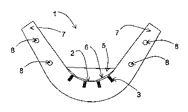
Figure 1 Cross-sectional illustration of a melt launder according to the
invention
Figure 2 Cross-sectional illustration of a melt launder according to another
embodiment of to the invention
Figure 3 Cross-section illustration of a melt launder according to a
preferred embodiment of the invention
In figure 1, there is seen a melt launder 1 according to a preferred
embodiment
of the invention, made of bent copper plate, and on the bottom 2 of said
launder there are made grooves 3. The figure is a cross-sectional illustration
showing the middle of the melt launder. The number of the grooves 3 made at .
the bottom of the copper plate can be any desired number, at least one. At the
launder bottom, the grooves are placed in an uncooled area, i.e. between the
lowest cooling channels. The grooves can be made either in connection with
casting, or by making them in the ready-made launder. According to this
preferred embodiment,. the grooves provided nearest to the edges cannot be
located nearer than 30 mm from the edge of the cooling channel 8. In shape,
the groove can represent any possible form. According to the present
embodiment, the grooves are 10 - 20 mm deep and 10 mm wide, at a distance
of 20 mm from each other. Said measures may vary depending on the size of
the melt launder. The melt launder comprises a required number of grooves in
the lengthwise direction of the launder, in addition to which both ends of the
launder are provided with transversal grooves that are not seen in the cross-
sectional illustration. Said transversal grooves are made at both ends of the
launder, and they extend from one launder edge to the other, so that a longer
working age is achieved for the launder. At both ends of the launder, the

CA 02466802 2004-04-15
WO 03/033982 PCT/FI02/00786
4
lengthwise grooves end at a transversal groove. The grooves 3 as well as the
transversal grooves are filled with fire-resistant mass that is partly 'worn
away
when tapping molten slag 5 and is autogenously replaced by solidified slag 6.
At the edges 7 of the launder, there are arranged cooling channels 8; they are
placed in an area that is not left under the melt when the melt 5 is being
tapped.
The cooling channels 8 are manufactured either in connection with slip casting
or by drilling lengthwise holes at' the edges 7 of a bent copper billet. In
the
cooling channels, there flows water that prevents excessive heating. A
required
number of channels is provided.
Figure 2 shows the end of a melt launder 9 according to another preferred
embodiment of the invention, seen in a cross-sectional illustration. It is
manufactured by compactly interconnecting two straight plates made of copper
or copper alloy, so that the edges 7 and the bottom 2 are made of said plates.
Now that area at the bottom 2 that gets into contact with the melt 5 is
provided
with grooves 3, which are then filled with fire-resistant mass. The melt
launder
is provided with a necessary amount of grooves 3, proceeding in the lengthwise
direction thereof, as well as with two transversal grooves 12 arranged at both
ends of the launder. The transversal grooves are made at both ends of the
launder, and they extend from one launder edge 7 to the other, so that a
longer
working life is achieved for the launder. At both ends of the launder, the
lengthwise grooves of the launder end in a transversal groove. Partly the
grooves .are worn away when tapping slag or when cleaning the launder, and
they are autogenously replaced by solidified slag 6. The grooves can be made
either in connection with casting or by working them in a ready-made launder.
The cooling channels 8 are placed at the edges 7 in the lengthwise direction
of
the melt launder, so that~they are not left underneath the melt surface.
Figure 3 illustrates a preferred embodiment of the invention. The bottom 11
and
the edges 7 of the melt launder 10 are manufactured of separate parts. The
bottom 11 is bent of metal and provided with grooves 3. The edges 7 made of
straight plates are connected to the bottom 11, so that a sufficient
compactness

CA 02466802 2004-04-15
WO 03/033982 PCT/FI02/00786
and heat transfer are achieved. The melt launder is provided with a required
number of grooves in the lengthwise direction thereof, in addition to which
both
ends of the launder are provided with transversal grooves that are not shown
in
the cross-sectional illustration. The transversal grooves are made at both
ends
5 of the launder, and they extend from one edge of the launder to the other,
so
that a longer working life for' the launder is achieved. At both ends of the
launder, the lengthwise grooves end in a transversal groove. The grooves 3 as
well as the transversal grooves are filled with a fire-resistant mass that is
partly
worn away when tapping molten slag 5 and is autogenously replaced by
solidified slag 6. The edges 7 are provided with cooling channels 8, located
above the melt surface 5.
For a mart skilled in the art, it is apparent that the various preferred
embodiments of the invention are not restricted to those described above, but
may vary within the scope of the appended claims.

Dessin représentatif
Une figure unique qui représente un dessin illustrant l'invention.
États administratifs

2024-08-01 : Dans le cadre de la transition vers les Brevets de nouvelle génération (BNG), la base de données sur les brevets canadiens (BDBC) contient désormais un Historique d'événement plus détaillé, qui reproduit le Journal des événements de notre nouvelle solution interne.

Veuillez noter que les événements débutant par « Inactive : » se réfèrent à des événements qui ne sont plus utilisés dans notre nouvelle solution interne.

Pour une meilleure compréhension de l'état de la demande ou brevet qui figure sur cette page, la rubrique Mise en garde , et les descriptions de Brevet , Historique d'événement , Taxes périodiques et Historique des paiements devraient être consultées.

Historique d'événement

Description Date
Demande non rétablie avant l'échéance 2007-10-09
Le délai pour l'annulation est expiré 2007-10-09
Réputée abandonnée - omission de répondre à un avis sur les taxes pour le maintien en état 2006-10-10
Inactive : CIB de MCD 2006-03-12
Inactive : Page couverture publiée 2004-06-29
Lettre envoyée 2004-06-25
Inactive : Notice - Entrée phase nat. - Pas de RE 2004-06-25
Demande reçue - PCT 2004-06-14
Exigences pour l'entrée dans la phase nationale - jugée conforme 2004-04-15
Demande publiée (accessible au public) 2003-04-23

Historique d'abandonnement

Date d'abandonnement Raison Date de rétablissement
2006-10-10

Taxes périodiques

Le dernier paiement a été reçu le 2005-10-03

Avis : Si le paiement en totalité n'a pas été reçu au plus tard à la date indiquée, une taxe supplémentaire peut être imposée, soit une des taxes suivantes :

  • taxe de rétablissement ;
  • taxe pour paiement en souffrance ; ou
  • taxe additionnelle pour le renversement d'une péremption réputée.

Veuillez vous référer à la page web des taxes sur les brevets de l'OPIC pour voir tous les montants actuels des taxes.

Historique des taxes

Type de taxes Anniversaire Échéance Date payée
Taxe nationale de base - générale 2004-04-15
Enregistrement d'un document 2004-04-15
TM (demande, 2e anniv.) - générale 02 2004-10-08 2004-04-15
TM (demande, 3e anniv.) - générale 03 2005-10-11 2005-10-03
Titulaires au dossier

Les titulaires actuels et antérieures au dossier sont affichés en ordre alphabétique.

Titulaires actuels au dossier
OUTOKUMPU OYJ
Titulaires antérieures au dossier
ARI JOKILAAKSO
ILKKA KOJO
Les propriétaires antérieurs qui ne figurent pas dans la liste des « Propriétaires au dossier » apparaîtront dans d'autres documents au dossier.
Documents

Pour visionner les fichiers sélectionnés, entrer le code reCAPTCHA :


Pour visualiser une image, cliquer sur un lien dans la colonne description du document. Pour télécharger l'image (les images), cliquer l'une ou plusieurs cases à cocher dans la première colonne et ensuite cliquer sur le bouton "Télécharger sélection en format PDF (archive Zip)" ou le bouton "Télécharger sélection (en un fichier PDF fusionné)".

Liste des documents de brevet publiés et non publiés sur la BDBC .

Si vous avez des difficultés à accéder au contenu, veuillez communiquer avec le Centre de services à la clientèle au 1-866-997-1936, ou envoyer un courriel au Centre de service à la clientèle de l'OPIC.


Description du
Document 
Date
(aaaa-mm-jj) 
Nombre de pages   Taille de l'image (Ko) 
Description 2004-04-15 5 241
Revendications 2004-04-15 2 57
Abrégé 2004-04-15 1 12
Dessins 2004-04-15 2 22
Dessin représentatif 2004-04-15 1 5
Page couverture 2004-06-29 1 26
Avis d'entree dans la phase nationale 2004-06-25 1 193
Courtoisie - Certificat d'enregistrement (document(s) connexe(s)) 2004-06-25 1 105
Courtoisie - Lettre d'abandon (taxe de maintien en état) 2006-12-05 1 175
Rappel - requête d'examen 2007-06-11 1 118
PCT 2004-04-15 14 510