Note : Les descriptions sont présentées dans la langue officielle dans laquelle elles ont été soumises.
CA 02466814 2004-05-11
1
TITLE OF THE INVENTION
Automated double saw
FIELD OF THE INVENTION
[0001] The present invention relates to saws. More specifically, the
present invention is concerned with an automated double saw.
BACKGROUND OF THE INVENTION
[0002] In the industry of door and window manufacturing for
instance, machining equipment is needed for installation, modification and
repair, and efforts are being made to automate available equipment.
[0003] It appears that conventional sawing tools fail to meet
particular needs in industry manufacturing, especially considering an ongoing
rapid evolution in the conception and fabrication processes. For example,
vinyl
extrusions now appearing on the market have dimensions outgrowing the
cutting capacity of current saws and are available with a variety of shapes
that
challenges the limit of versatility of the conventional tools. In particular,
the wide
range of thickness now available for vinyl extrusions results in repeated and
time-consuming tool adjustments, thereby jeopardizing productivity.
[0004] Therefore, there is a need for tools allowing enhanced
performances in terms of speed and dimensionality control for example, as well
as allowing a wider range of operating conditions in order to adapt to a
varied
geometry of work pieces, while remaining cost-effective.
CA 02466814 2004-05-11
2
SUMMARY OF THE INVENTION
[0005] More specifically, in accordance with the present invention,
there is provided a saw for processing a work piece conveyed by a timing belt,
comprising a cutting bench; a first saw head mounted on the cutting bench; and
a second saw head mounted on the cutting bench; the cutting bench being in
contact with a measured surface of the work piece used as a reference surface,
and each one of the first and the second saw heads comprising a saw blade.
[0006] Other objects, advantages and features of the present
invention will become more apparent upon reading of the following non-
restrictive description of embodiments thereof, given by way of example only
with reference to the accompanying drawings.
BRIEF DESCRIPTION OF THE DRAWINGS
[0007] In the appended drawings:
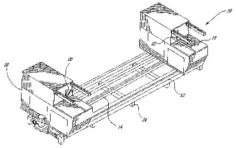
[0008] Figure 1 is a general perspective view of a tool according to
an embodiment of the present invention;
[0009] Figures 2 are close up perspective views of a saw head of the
tool of Figure 1 with a saw at an angle of 90°;
[0010] Figures 3 are close up perspective views of a saw head of the
tool of Figure 1 with a saw at an angle of 45°;
[0011] Figures 4 are close up front perspective views of a structural
support for the saw of the tool of Figure 1;
CA 02466814 2004-05-11
3
[0012] Figures 5 are close up rear perspective views of the structural
support of Figures 4; and
[0013] Figures 6 are further close up front perspective views of a
structural support for the saw of the tool of Figure 1.
DESCRIPTION OF EMBODIMENTS OF THE INVENTION
[0014] There is provided a saw that alleviates the limitation of the
prior art.
[0015] As illustrated in Figure 1 of the appended drawings, the saw
comprises a structural stand 12, a timing belt 14 extending from a first top
bench 16 and a second top bench 18, a first saw head 20 mounted on the first
top bench 16 and a second saw head 22 mounted on the second top bench 18.
[0016] The structural stand 12, which may optionally be provided
with adjustable structural support arms 24, is strong and distortion-free. The
overall length between the first top bench 16 and the second top bench 18 may
be adjusted, of up to 3.5 meters.
[0017] The first top bench 16 and the second top bench 18 provide
for a cutting bench in contact with a measured surface of a work piece to be
processed, which results in an increased precision of cut since the measured
surface is used as a reference surface, in contrast with equipment where the
work piece has a measured surface thereof upwards.
CA 02466814 2004-05-11
4
[0018] Obviously the provision of two cutting heads 20, 22 allow an
increased cutting rate. One of the two cutting heads 20, 22 is mobile on the
timing belt 18, while the other one is fixed.
[0019] The present invention comprises optimizing the structure of
the cutting head by reducing a number of components thereof and by reducing
the dimensions of the remaining components thereof, thereby allowing to strike
an optimized balance between the cutting path, the cutting height (as measured
by the rake angle) and the dimensions of the cutting bench of the saw.
[0020] Since the two saw heads 20 and 22 are essentially identical,
only the saw head 20 will be described herein for concision purposes, in
relation to Figures 2 to 6 of the appended drawings.
[0021] The saw head 20 comprises a saw housing 30 receiving a
saw blade 32.
[0022] An increased cutting path, up to 15" (381 mm) by 25" (635
mm) is obtained by using larger saw blades 32. The center of the saw blades
32 are positioned lower that the benches 16, 18, which allows a longer travel
of
the saw blades 32, referred to as the cutting length.
[0023] The advance of the saw blade 32 is performed by a
hydropneumatic arrangement adjustable by a flow-regulating valve to provide
an increased cutting rate and cutting precision by operating simultaneously on
both cutting heads.
CA 02466814 2004-05-11
[0024] A rear movement mechanism allows a movement of the
blade 32 from the rear end of the saw 10, radially under the cutting bench 16,
which permits to accommodate a blade of an increased diameter in comparison
to a diameter of 18" for the diameter of the blades that can currently be
mounted on the available tools, without requiring a larger length of the saw
housing 30. Moreover, the lowered position center of the blades permits a
higher blade diameter and an increased cutting length. Also, the lager
diameter
allows a larger cutting height.
[0025] Thus, it makes possible to determine dimensions of the
workpiece to be cut on the basis of the dimensions of the window frame instead
of on the basis of the dimensions of the windowpane, in the case of a window
application for example. Such a feature results in the elimination of lengthy
and
fastidious iterative adjustments and corrections that are usually necessary
when cutting different workpieces.
[0026] A cross-cut indexation mechanism is provided which will be
detailed hereinafter in relation to Figures 4 to 6
[0027] Both mechanisms contribute to an enhanced cutting capacity
over a widened range of shape, dimension and thickness of objects to be cut,
by allowing an increased control of the rotation speeds and of the advance of
the saw blade.
[0028] A correction mechanism is provided for adjusting and
maintaining a reference point of the saw to accommodate the shapes,
dimensions and variability in thickness of the work piece. This correction
mechanism allows maintaining the reference point of the saw with a constant
precision over the range of rake angles and over the cutting length.
CA 02466814 2004-05-11
6
[0029] The saw blade 32 may be accommodated for angle cuts
between 45° (Figure 2) and 90° (Figure 3) to either side, by an
indexation
mechanism of the blade controlled by a computer.
[0030] Within the saw housing 30, the saw blade 32 is mounted by
ball bearings on an axis 34 supported by an arm 48 extending from a support
38 mounted on a base 46. The support 48-36 is movable under the action of a
cylinder 40 having a first end connected to the base 38 and a second end
mounted on the support 42 by a rotating cog mounted on pinion bearings 54,
thereby controlling the movement of the support 48-36 around a pivot mount
44.
[0031] As can be best seen in Figures 4 and 6, a structural support
of rotation connecting the arm 36 to the support 38 comprises a plate 48
rotatable around the pivot mount 44 and transferring the indexation movement
by a rack-and-pinion arrangement 54. Moreover, a cog mechanism 50 allows a
precise control of the movement, whereas ball bearings 52 mounted o bearing
supports 53 and an arched rail 54 provide stability. The arched rail is a
profiled
rail treated against corrosion, by fluorination for example. This structural
support of rotation also allows adjustment of the cutting angle to accommodate
workpieces of varying thickness.
[0032] People in the art will appreciate that the present invention
allows a rake angle in the range comprised between 45° and 90°,
in sharp
contrast with existing mechanisms allowing either a rake angle of 45°
or a rake
angle of 90°.
[0033] From the foregoing, it should now be apparent that the saw of
the present invention has an optimized cutting head structure, including a
CA 02466814 2004-05-11
7
structural support for the rotation of the blade and a mechanism of indexation
of
the rake angle, which allows using blades of a large diameter, for example
20",
22" and 24". Moreover, the structure is adaptable to any dimension of a
workpiece and to variability in the thickness of the workpiece of 0.5 mm as
compared to 0.15 mm in the current tools.
[0034] Prior art tools are limited to use blades of a diameter of 18"
(457,2 mm), and to machine extrusions less than 4" in thickness, while
available extrusions may now have a thickness reaching 4'/2" (114,3 mm) at an
angle of 45 degrees, which requires, when considering the thickness of the
template, a cutting height of up to 5" (127 mm), i. e. blades of a diameter of
22"
(558,8 mm) or up to 24" (609,6 mm). The cutting head optimizing of the present
invention results in an increase of the cutting path and of the cutting height
without modifying the dimensions of the cutting bench, and also in an increase
the cutting path without reducing the precision of the reference point of the
saw.
[0035] The workpiece to be cut by the saw of the present invention
may be a plastic profile for a door or a window for example. People in the art
will appreciate that the present invention is suitable for cutting aluminum,
wood
and vinyl profiles and similar material.
[0036] Clearly, a multiple angle saw according to the present
invention is capable of cutting round top windows, round top sills, octagon
windows. Each saw blade may be stroke independently. Moreover, the angle of
each saw blade can be adjusted to a range of angles by replacing the cylinder
40 and the pinion bearings 42 (see Figure 5) by an electric step motor for
example.
CA 02466814 2004-05-11
[0037] The saw blade used herein may be for example carbide
tipped circular saw blade.
[0038] Interestingly, the tool of the present invention may be fully
automated and programmable, and remotely monitored from an operator
control station. Automation may be achieved according to custom needs by
using versatile electronic components.
[0039] People in the art will appreciate that the saw of the present
invention benefits from an improved structural support of rotation, of a
controlled indexation of the rake angle and of an advantageous mechanism of
the blade movement, yielding an enhanced control of the speed and of the
advance of the saw blades.
[0040] Therefore, the saw of the present invention meets a range of
varied needs related to an increasing variety of shapes and dimensions of
vinyl
extrusions for doors and windows for example, including the range of thickness
thereof, in terms of cutting capacity, cutting rate, and precision of cut.
[0041] Although the present invention has been described
hereinabove by way of embodiments thereof, it may be modified, without
departing from the nature and teachings of the subject invention as defined in
the appended claims.