Sélection de la langue

Search

Sommaire du brevet 2468141 

Énoncé de désistement de responsabilité concernant l'information provenant de tiers

Une partie des informations de ce site Web a été fournie par des sources externes. Le gouvernement du Canada n'assume aucune responsabilité concernant la précision, l'actualité ou la fiabilité des informations fournies par les sources externes. Les utilisateurs qui désirent employer cette information devraient consulter directement la source des informations. Le contenu fourni par les sources externes n'est pas assujetti aux exigences sur les langues officielles, la protection des renseignements personnels et l'accessibilité.

Disponibilité de l'Abrégé et des Revendications

L'apparition de différences dans le texte et l'image des Revendications et de l'Abrégé dépend du moment auquel le document est publié. Les textes des Revendications et de l'Abrégé sont affichés :

  • lorsque la demande peut être examinée par le public;
  • lorsque le brevet est émis (délivrance).
(12) Demande de brevet: (11) CA 2468141
(54) Titre français: DISPOSITIF D'ATTENUATION DE BRUIT
(54) Titre anglais: NOISE ATTENUATOR ARRANGEMENT
Statut: Réputée abandonnée et au-delà du délai pour le rétablissement - en attente de la réponse à l’avis de communication rejetée
Données bibliographiques
(51) Classification internationale des brevets (CIB):
  • F02K 01/34 (2006.01)
  • F01D 17/10 (2006.01)
(72) Inventeurs :
  • BRISTOW, ANDREW (Royaume-Uni)
  • YEOMANS, KEVIN (Royaume-Uni)
  • HILLYER, DARREN (Royaume-Uni)
(73) Titulaires :
  • DUNLOP AEROSPACE LIMITED
(71) Demandeurs :
  • DUNLOP AEROSPACE LIMITED (Royaume-Uni)
(74) Agent: ROBIC AGENCE PI S.E.C./ROBIC IP AGENCY LP
(74) Co-agent:
(45) Délivré:
(86) Date de dépôt PCT: 2002-11-20
(87) Mise à la disponibilité du public: 2003-06-05
Licence disponible: S.O.
Cédé au domaine public: S.O.
(25) Langue des documents déposés: Anglais

Traité de coopération en matière de brevets (PCT): Oui
(86) Numéro de la demande PCT: PCT/GB2002/005230
(87) Numéro de publication internationale PCT: GB2002005230
(85) Entrée nationale: 2004-05-19

(30) Données de priorité de la demande:
Numéro de la demande Pays / territoire Date
0127952.0 (Royaume-Uni) 2001-11-21
0209371.4 (Royaume-Uni) 2002-04-24

Abrégés

Abrégé français

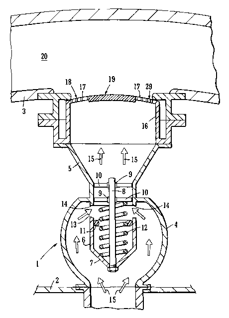
L'invention concerne un appareil de libération de fluides sous pression, comprenant une ouverture (1) à travers laquelle peuvent passer les fluides sous pression et un élément (16) d'atténuation s'étendant au-dessus de ladite ouverture. L'élément (16) d'atténuation permet de régler le débit dudit fluide et d'atténuer le bruit associé.


Abrégé anglais


Apparatus for the release of pressurised fluids comprising an opening (1)
through which pressurised fluids may pass and an attenuator member (16)
extending over said opening. The attenuator member (16) operates to control
the flow of said fluid and attenuate sound associated therewith.

Revendications

Note : Les revendications sont présentées dans la langue officielle dans laquelle elles ont été soumises.


8
CLAIMS
1. An air bleed system for a turbofan aircraft engine, the system comprising
duct means
(1, 5) for receiving air from a compressor stage of the engine and directing
said air to a
bypass duct (20) of the engine valve means (4, 8) within the duct means for
controlling
the flow of said air, and a sound attenuator member (16) extending aver the
duct
means downstream and having apertures (17, 31, 32, 33) distributed over the
member
for passing said air, characterised in that the apertures of the attenuator
member (16)
are arranged for the distribution of the air passing through the attenuator
member to be
relatively more restricted in a central region (19) of the member than in
another region
(18) outside said central region.
2. A system according to claim 1, wherein said another region is an annular
region
extending round said central region.
3. A system according to claim 1 or claim 2, wherein the valve (4) and
attenuator member ~~
are constructed for the pressure drop from the upstream to the downstream side
of the
valve member (6) to be substantially equal to the pressure drop through the
attenuator
member.
4. A system according to claim 1, 2 or 3, wherein the attenuator member is
positioned for
a high pressure stream of air from the valve to impinge upon said central
region.
5. A system according to claim 1, 2, 3 or 4 wherein the attenuator member
comprises a
substantial number of relatively small perforations (17) distributed over a
peripheral

9
region of the attenuator member and no or relatively few such apertures in the
central
region (19).
6. A system according to claim 1, 2, 3 or 4, wherein the attenuator member has
apertures
(31, 32, 33) differentially distributed over the attenuator member and porous
material
adjacent at least some of the apertures.
7. A system according to claim 6, wherein the porosity and/or thickness of the
porous
material is different in different regions of the attenuator member.
8. A system according to claim 1, 2, 3 or 4, wherein the attenuator member
comprises
porous material for defining said apertures, the porosity and/or thickness of
the porous
material being different in different regions of the attenuator member.
9. A system according to claim 6, 7 or 8, wherein the porous material is
porous metallic
foam.
10. Apparatus according to any preceding claim, wherein the valve is a bullet
valve.

Description

Note : Les descriptions sont présentées dans la langue officielle dans laquelle elles ont été soumises.


CA 02468141 2004-05-19
~~ ~~ ~~~~,ENCE SHAW ~ ASSOCIATES; 0121.4544523; 22-Apr-a4 16:57; Pa'~27~~~~~~
~,
,_
A,gent~ ref: Pd3814P(;:'l.'
ATTENUATOR ARRANGEMENT
This invention relates to an attenuator for reducing noise associated with an
air bleed system
particularly, but not exclusively, for a turbofan aircraft engine.
In an aircraft engine, particularly a large high bypass ratio turbofan, it may
be necessary for
the best operation of the engine to bleed air pressure from within the
compressor. To da
this, a servo-controlled valve can be provided in ducting leading tram the
compressor casing
to the fan by-pass duct. Normally, there would be an array of several bleed
valves spaced
1o around the axis of the engine. Also, two or more valves ar valve arrays may
be provided at
different stages of the compressor. The different valves ar valve arrays are
opened and
closed, or sometimes modulated, i.e. set to give a required flow rate between
on and off by
an engine management system. The valves are controlled by this system along
with other
engine parameters to optimise the operation of the engine far different
operating conditions.
The release of high pressure air into the fan by-pass duct can create
considerable noise and,
at least in relation to valves which may open at low altitude when the
aircraft is taxiing, taking
off or landing, sound attenuation is required.
zo Patent application number Gi32,132,269A discloses an attenuatvrfora gas
turbine engine air
.bleed valve. The attenuatar receives the plume of high pressure air from a
compressor stage
of the engine and has a large number of small holes which convert the stream
to a
multiplicity of air jets.
Patent application number EP0354151A3 discloses a muffler plate for a
refrigeration system
compressor with a few relatively large hales arranged round a check valve.
U5 patent number 5,906,25 shaves a refrigeration system expansion valve with
an elongate
attenuator member made of porous material. ,
EmFf.~eit:~~l04I~C1fJ4 17:57 ;AMENDED SHEETrfi81 P.008
... .~ .,.. ~ ,. .., ~.. ,. ,

:~~! .~~uA...-.
CA 02468141 2004-05-19
ENCE SHAW 8~ ASSOCIATES; 01214544523; 22-Apr-04 18:57; Pa Q2'l'l'7J~~~~' E~',
_ riA: ,~ :.: .
2
According tp the invention, there is provided an air bleed system far a
turbofan aircraft
engine, the system comprising duct rneans for receiving air from a compressor
stage of the
engine and directing said air to a bypass duct of the engine valve means
within the duct
means for cantrc~liing the flow of said air, and a sound attenuator member
extending over the
duct means downstream and having apertures distributed over the member for
passing said
air, characterised in that the aperkures of the attenuator member are arranged
for the
distribution of the alt passing through the attenuatar member to be
relati~rely more restricted
irz a central region of the member than in another region outside said central
region.
i0 Said another ~egian is an annular region extending round said central
region.
Preferably, the valve and attenuator member are constructed for the pressure
drop from the
upstream to the downstream tide of the value member to be substantially equal
to the
pressure drop through the attenuator member.
The attenuator member may be positioned for a high pressure stream of air from
the valve to
impinge upon said central region.
Advantageously, the attenuator member comprises a substantial number of
relatively small
2Q perforations distributed over a peripheral region of the attenuator member
and no or
relatively few such apertures in the central region.
Preferably, the attenuator member has apertures differentially distributed
over the attenuatvr
member and porous material adjacent at least some of the aperkures,
Empf.zPit:~~/O~/~C~04 17:57 ~I~M,ENDEp SH~~Ty,6u1 P.C1C1~
.,. , . .. ~ ~.. . .~.. ~... .. ~. . ..

CA 02468141 2004-05-19 ,' E,
~(~~ ~'~,7~~(~'~,~,~ENCE SHAW ~ ASSOCIATES; 01214544523; 22-Apr-04 16:58; Fa
(~~;~'~~'~~5u,~,'~ ,
3
The porosity andlor thickness of the porous material may be different in
different regions of
the aitenuator member.
The attenuator member may comprise porous material for defining said
apertures, the
porosity and/or thickness of tile porous material being different in different
regions of the
attenuator member.
The porous material rnay be porous metallic foam.
l0 The valve may be a bullet valve.
Em~~,~eit:~~104/~004 17:57 ~AIVIENDED Sf-I~ETi~81 P.O10
. .. ~ . .,.. :. ,, .. . .. " .. ~, "~;~

CA 02468141 2004-05-19
WO 03/046358 PCT/GB02/05230
4
Referring to Figures 4 to 6, there is shown a number of alternative layouts of
holes in the
cover 29 of the attenuator 16. The size, shape and positioning of the holes
31, 32, 33 may
be changed to suit different flow-rates of air. A Retimet foam layer 35 may be
provided
beneath the member 16.
In the embodiment shown in Figure 7, the cover 29 of the attenuator 16 is
omitted and
effectively replaced entirely by a self supporting layer of Retimet foam layer
35.
The metal foam 35 could incorporate different grades of foam; for example, the
centre area
32 could be of a grade more restrictive to flow than the outer area.
Foams are graded with a number system representing the number of pores/cells
per linear
inch; e.g. 80 grade has 80 cells per inch. It is expected that the range of
foams suitable for
this application would be in the range 5 to 150 grade, and preferably be in
the range 10 to 80
grade.
Changes of the grade of the layer of metal foam 35 of Figures 3 to 7 could
produce different
noise reduction characteristics. For example different grades of foam with
different porosity
would reduce different noise frequencies.
A sandwich structure of layers of foam of different grades would alternate a
wider range of
noise frequencies and provide improved noise reduction. Also, by using foams
of different
thickness one could also change the noise reduction properties by changing the
flow rate.
This.needs to be balanced against the desired flow rate from the valve 6 and
the pressure
drop across the valve 6.

CA 02468141 2004-05-19
WO 03/046358 PCT/GB02/05230
The layer of metallic foam 35 of Figures 3 to 6 may have different zones of
different porosity
aligned with selected holes 31, 32, 33 in the cover 29. Similarly, the inserts
of metallic foam
35 of Figure 7 can have a different porosity for different zones. In this way,
one can
accommodate different airflow rates or different levels of sound attenuation
for different
s applications and thus provide greater flexibility in the design of the
characteristics of the
attenuator.
It is to be understood that the layer 35 of metallic foam shown in Figures 3
to 6 may be
replaced by individual inserts of metallic foam that are secured in each of
the holes 31, 32,
33.
It may be possible to use a mat of metal or other fibres to produce a similar
effect to the
metal foam to control flow rate and pressure drop across the valve 6 to reduce
noise. Such a
mat could be a woven or non-woven fibre structure or fabric.
The cover 29 might be required or desirable in some of those applications
where a foam
metal layer is used, for example, to restrict air flow more in some areas than
in other areas.
But in other applications the cover 29 may not be needed. Where a cover 29 is
used it may
be of any support structure such as perforated metal or plastics material or
could simply
2o comprise two mutually orthogonal sets of parallel wires or wire mesh to
retain the foam metal
layer 35 in place.

Dessin représentatif
Une figure unique qui représente un dessin illustrant l'invention.
États administratifs

2024-08-01 : Dans le cadre de la transition vers les Brevets de nouvelle génération (BNG), la base de données sur les brevets canadiens (BDBC) contient désormais un Historique d'événement plus détaillé, qui reproduit le Journal des événements de notre nouvelle solution interne.

Veuillez noter que les événements débutant par « Inactive : » se réfèrent à des événements qui ne sont plus utilisés dans notre nouvelle solution interne.

Pour une meilleure compréhension de l'état de la demande ou brevet qui figure sur cette page, la rubrique Mise en garde , et les descriptions de Brevet , Historique d'événement , Taxes périodiques et Historique des paiements devraient être consultées.

Historique d'événement

Description Date
Demande non rétablie avant l'échéance 2007-11-20
Le délai pour l'annulation est expiré 2007-11-20
Réputée abandonnée - omission de répondre à un avis sur les taxes pour le maintien en état 2006-11-20
Inactive : CIB de MCD 2006-03-12
Lettre envoyée 2005-06-13
Inactive : Transfert individuel 2005-05-16
Inactive : Lettre de courtoisie - Preuve 2004-09-28
Inactive : Page couverture publiée 2004-09-23
Inactive : Notice - Entrée phase nat. - Pas de RE 2004-09-21
Demande reçue - PCT 2004-06-23
Exigences pour l'entrée dans la phase nationale - jugée conforme 2004-05-19
Demande publiée (accessible au public) 2003-06-05

Historique d'abandonnement

Date d'abandonnement Raison Date de rétablissement
2006-11-20

Taxes périodiques

Le dernier paiement a été reçu le 2005-11-01

Avis : Si le paiement en totalité n'a pas été reçu au plus tard à la date indiquée, une taxe supplémentaire peut être imposée, soit une des taxes suivantes :

  • taxe de rétablissement ;
  • taxe pour paiement en souffrance ; ou
  • taxe additionnelle pour le renversement d'une péremption réputée.

Les taxes sur les brevets sont ajustées au 1er janvier de chaque année. Les montants ci-dessus sont les montants actuels s'ils sont reçus au plus tard le 31 décembre de l'année en cours.
Veuillez vous référer à la page web des taxes sur les brevets de l'OPIC pour voir tous les montants actuels des taxes.

Historique des taxes

Type de taxes Anniversaire Échéance Date payée
Taxe nationale de base - générale 2004-05-19
TM (demande, 2e anniv.) - générale 02 2004-11-22 2004-10-29
Enregistrement d'un document 2005-05-16
TM (demande, 3e anniv.) - générale 03 2005-11-21 2005-11-01
Titulaires au dossier

Les titulaires actuels et antérieures au dossier sont affichés en ordre alphabétique.

Titulaires actuels au dossier
DUNLOP AEROSPACE LIMITED
Titulaires antérieures au dossier
ANDREW BRISTOW
DARREN HILLYER
KEVIN YEOMANS
Les propriétaires antérieurs qui ne figurent pas dans la liste des « Propriétaires au dossier » apparaîtront dans d'autres documents au dossier.
Documents

Pour visionner les fichiers sélectionnés, entrer le code reCAPTCHA :


Pour visualiser une image, cliquer sur un lien dans la colonne description du document. Pour télécharger l'image (les images), cliquer l'une ou plusieurs cases à cocher dans la première colonne et ensuite cliquer sur le bouton "Télécharger sélection en format PDF (archive Zip)" ou le bouton "Télécharger sélection (en un fichier PDF fusionné)".

Liste des documents de brevet publiés et non publiés sur la BDBC .

Si vous avez des difficultés à accéder au contenu, veuillez communiquer avec le Centre de services à la clientèle au 1-866-997-1936, ou envoyer un courriel au Centre de service à la clientèle de l'OPIC.


Description du
Document 
Date
(aaaa-mm-jj) 
Nombre de pages   Taille de l'image (Ko) 
Abrégé 2004-05-18 2 60
Dessins 2004-05-18 6 171
Revendications 2004-05-18 2 80
Description 2004-05-18 5 194
Dessin représentatif 2004-05-18 1 19
Rappel de taxe de maintien due 2004-09-20 1 110
Avis d'entree dans la phase nationale 2004-09-20 1 201
Demande de preuve ou de transfert manquant 2005-05-23 1 100
Courtoisie - Certificat d'enregistrement (document(s) connexe(s)) 2005-06-12 1 114
Courtoisie - Lettre d'abandon (taxe de maintien en état) 2007-01-14 1 176
Rappel - requête d'examen 2007-07-22 1 119
PCT 2004-05-18 14 535
Correspondance 2004-09-20 1 26
Taxes 2004-10-28 1 28
Taxes 2005-10-31 1 28