Note : Les descriptions sont présentées dans la langue officielle dans laquelle elles ont été soumises.
CA 02469411 2004-06-04
WO 03/048638 PCT/US02/38741
-1-
EVAPORATOR AND EVAPORATIVE PROCESS
FOR GENERATING SATURATED STEAM
Technical Field
This invention relates in general to steam generators and more
particularly to evaporator for a steam generator and to an evaporation
process.
Background Art
Much of the equipment for generating electrical power relies on
steam, and so do a variety of industrial processes. In either case, hot gases,
in many instances generated by combustion, pass through a generator
which converts water into superheated steam. Typical of these installations
are heat recovery steam generators (HRSGs) which are used to extract heat
from the hot gases discharged by gas turbines that drive electrical
generators. The heat extracted produces steam which passes on to a steam
turbine that powers another electrical generator.
The typical steam generator, aside from a duct through which the
hot gases pass, in its most basic form, includes three additional components
- namely, a superheater, an evaporator, and an economizer or feedwater
heater arranged in that order with respect to the flow of gases in the duct.
The water flows in the opposite direction, that is through the economizer
where it is heated, but remains a liquid, then through the evaporator where
it is converted into saturated steam, and then through the superheater where
the saturated steam becomes superheated steam.
Evaporators come in two basic configurations - the circulation type
and the once-through type - each with its own advantages and
disadvantages. Both have an array of tubes in the duct through which the
hot gases pass.
In the circulation type, the tubes reside in a circuit with a steam
drum that is above the tubes. The drum contains water which flows from
the drum, through a downcomer, and then into the tubes where some of it is
converted into steam, but the steam exists as bubbles within the water, and
is returned through a riser into the steam drum. Here the steam, which is
CA 02469411 2004-06-04
WO 03/048638 PCT/US02/38741
-2-
saturated, separates from the liquid water and passes on to the superheater.
It is replaced by feedwater which is supplied to the drum. The tubes of a
circulation evaporator remain wet all the time - that is to say, liquid water
exists against their interior surfaces throughout - and this promotes good
heat transfer. Moreover, impurities, such as dissolved salts, concentrate in
the water within the drum and the remainder of the circulation loop, leaving
the saturated steam that escapes largely free of them. A small water flow,
known as blowdown, is extracted from the drum to control the
accumulation of impurities. Most circulation evaporators rely entirely on
the variance in density between the water in the downcomer and the water-
steam mixture in the tubes to circulate the water in the evaporator, although
some have a pump assist. Furthermore, a circulation evaporator contains a
reservoir of stored water. Thus, the failure of a pump does not immediately
affect the operation of the evaporator and render it vulnerable to
1 S overheating. Also, circulation evaporators operate very well over a wide
range of load conditions. Finally, circulation evaporators predominate, and
as a consequence boiler operators are familiar with their operation.
But circulation evaporators have their detractions. Perhaps the
greatest of these is the expense attributable to steam drums, large
downcomers and headers to supply water to their tubes. Moreover, the
reservoirs of water contained in them require time to bring up the boiling
temperature, so the start-up time for a circulation evaporator is extended.
Once-through evaporators do not require downcomers or drums, so
the only stored water in them resides in the tubes themselves. This enables
a once-through evaporator to be brought to operating conditions more
rapidly than a natural circulation evaporator. However, a once-through
evaporator must completely convert the water into steam, so that only
saturated steam escapes and flows on to the superheater. No liquid water
should leave the evaporator. As a consequence, regions of the tubes run
dry, that is to say, their interiors are not wetted by liquid water. The
transfer of heat diminishes significantly in these regions, even though the
regions operate at temperatures in excess of the wetted regions. Some
CA 02469411 2006-12-04
3
manufactures of once-through evaporators resort to high alloy metals to enable
the tubes
to better withstand the elevated temperatures. Whereas, a circulation
evaporator
discharges steam that is largely free of impurities, a once-through evaporator
will
discharge steam containing all the impurities present in the feedwater that is
pumped into
it. Therefore, the feedwater needs to be treated to eliminate as many
impurities as
possible.
Thus, circulation and once-though evaporators each have advantages and
disadvantages.
Summary of the Invention
~ The present invention resides in an evaporator that possesses many of the
advantages of both a circulation evaporator and a once-through evaporator, but
few of
the disadvantages. To this end, it includes first tubes located in a flow of
hot gasses,
second tubes also located in the flow, and a vessel connected to both the
first and second
tubes such that it receives water from the first tubes and such that water
from in the
vessel circulates through the second tubes and back to the vessel. The
invention also
resides in the process embodied in the operation of the evaporator.
The present invention provides an evaporator for extracting heat from a stream
of
hot gases to convert liquid water into saturated steam, said evaporator
comprising: first
tubes located in the stream and connected to a source of liquid water, such
that the liquid
water is circulated through the first tubes at a flow rate which enables the
first tubes to
convert the water into a mixture of water and steam, with the quality of the
steam being
at least about 20% a vessel in communication with the first tubes for
receiving the liquid
water from the first tubes; second tubes located in the stream of hot gases
and being
connected to the vessel such that water from the vessel will circulate into
the second
tubes and then back into the vessel; and a discharge on the vessel for
enabling saturated
steam to escape from the vessel.
The present invention further provides in combination with a duct though which
hot gases flow and an economizer located in the duct for elevating the
temperature of
liquid water, an evaporator for converting liquid water from the economizer
into steam,
said evaporator comprising: first tubes located in the duct; second tubes
located in the
duct; a pump for forcing liquid water through the first tubes at a rate
sufficient to enable
the water to wet the interiors of the first tubes in their entireties, while
steam develops in
that water, whereby liquid water with steam entrained in it is discharged from
the first
tubes; and a drum connected with the first tubes such that it receives from
the first tubes
CA 02469411 2006-12-04
3a
the liquid water, the drum also being connected with the second tubes such
that water
from the drum circulates through the second tubes and back to the drum, with
the
water developing steam in the second tubes while the interiors of the second
tubes
remain wetted by the water in their entireties.
The present invention further provides a process for producing saturated
steam from a flow of hot gases, said process comprising: introducing liquid
water
into first tubes that are located in the flow of the gases, forcing the liquid
water
through the tubes at rate sufficient to enable the interiors of the tubes to
be fully
wetted by the water while steam develops within the water, with the steam
having a
quality of at least 20%, whereby the water upon leaving the first tubes has
steam
entrained in it; separating the entrained steam from the liquid water leaving
the first
tubes; introducing the liquid water from the first tubes into a vessel;
circulating the
liquid water from the vessel through second tubes that are located in the flow
of
gases, and then back into the vessel, with the circulation being such that the
interiors
of second tubes remain wetted in their entireties by the water, yet steam
develops in
the water so that the water entering the vessel from the second tubes has
steam
entrained in it; and in the vessel separating the entrained steam from the
water
leaving the second tubes.
Brief Description of Drawings
FIG. 1 is a schematic sectional view of a steam generator equipped with an
evaporator constructed in accordance with and embodying the present invention;
and
FIG. 2 is a schematic view of the evaporator.
Best Mode for Carrying Out the Invention
Referring now to the drawings, a steam generator A (FIG. 1 ) basically
includes a duct 2 having an inlet end 4 and a discharge end 6. The inlet end 4
is
connected to a source of hot gases, such as a gas turbine or an incinerator,
and those
gases flow through the duct 2, leaving at the discharged end 6. In addition,
the steam
generator A includes a superheater 12, an evaporator 14, and a feedwater
heater or
economizer 16 arranged in the duct 2 in that order from the inlet end 4 to the
outlet
end 6. Thus, the hot gases flow first through the superheater 12, then through
the
evaporator 14, and finally through the economizer 16. Water flows in the
opposite
CA 02469411 2004-06-04
WO 03/048638 PCT/US02/38741
-4-
direction. More specifically, the economizer 16 is connected to a feedwater
pump 18 which delivers feedwater as a liquid to the economizer 16. It
extracts heat from the hot gases and transfers that heat to the liquid water
that flows through it, thereby elevating the temperature of the water.
Leaving the economizer 16, the liquid water then flows to the evaporator 14
through which it passes. The evaporator 14 elevates the temperature of the
liquid water still higher - indeed, high enough to convert some of it to
saturated steam. The saturated steam flows into the superheater 12 which
raises its temperature, transforming it into superheated steam which may be
used to power a turbine or in some industrial process or even to heat a
building. The superheater 12 and economizer 16 are basically tube banks.
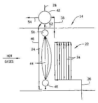
The evaporator 14 is more complex.
. The evaporator 14, to a measure, represents a combination of a
once-though evaporator and a natural circulation evaporator. As such it
includes (Fig. 2) a once-through section 22 and a natural circulation section
24. Heated water from the economizer 16, which water is in the liquid
phase, is introduced into the once-through section 22 at a feed line 26 and
in the two sections 22 and 24 is transformed into saturated steam which is
discharged from the natural circulation section 24 into a discharge line 28
which delivers it to the superheater 12.
Considering the once-through section 22 first, it includes (Fig. 2)
tubes 34 that lie within the duct 2, so that the hot gases pass over them. It
also includes a connecting line 36 that leads to the natural circulation
section 24. The economizer 16 delivers warm water to the tubes 34 of the
once-through section 22 where some of the water is converted into
saturated steam in the tubes 34. The flow is such that the outlet quality of
the steam remains low and the interiors of the tubes 34 remain wetted in
their entireties, and this flow is controlled by the feedwater pump 18. Thus,
liquid water, even though it may contain bubbles of saturated steam, exists
in the interiors of the tubes 34. In contrast to a conventional once-though
evaporator, the tubes 34 of the once-through section 22 possess no dry
walls. Indeed, the arrangement is such as to insure that the tubes 34 remain
CA 02469411 2004-06-04
WO 03/048638 PCT/US02/38741
-5-
wetted throughout, and also to insure that the quality of the steam in the
connecting line 36 ranges between 20% and 90% and preferably between
40% and 60%. "Quality" means the fraction by weight of the mixture of
water and steam that is actually steam. Thus, a flow with 40% quality
steam contains 40% steam by weight and 60% liquid water by weight.
The natural circulation section 24 includes (Fig. 2) a steam drum 42,
which is a vessel located outside and above the duct 2, and tubes 44 which
are located in the duct 2. In addition, the natural circulation section 24 has
a downcomer 46 which leads downwardly from the drum 42, outside of the
duct 2, and at its lower end opens into a distribution header 48 that extends
through the duct 2 where the lower ends of the tubes 44 are connected to it.
Also, the natural circulation section 24 has a collection header 50 into
which the upper ends of the tubes 44 open within the duct 2 and risers 52
which lead from the collection header 50 to the drum 42. Finally, the drum
42 has a blowdown line 54 connected to it.
The steam drum 42, the downcomer 46, the two headers 48 and 50,
as well as the tubes 44 between them and the risers 52, all contain liquid
water, and that water comes from the once-through section 22. To this end,
the connecting line 36 from the tubes 34 of the once-through section 22
opens into the drum 42. The once-through section 22 delivers enough
liquid water to the drum 42 to maintain the drum 42 partially filled with
liquid water all the time. The connecting line 36 opens into the drum 42,
below the water level in the drum 42 as do the risers 52. The downcomer
46 and the blowdown line 54 lead from the drum 42 below the water level
in the drum 42.
The tubes 34 and 44 of the two sections 22 and 24, respectively,
may be organized side-by-side in the duct 2, or with the tubes 34 ahead of
the tubes 44, or with the tubes 44 ahead of the tubes 34. The last is
preferred.
In the operation of the steam generator A, the feedwater pump 18
delivers relatively cool feedwater to the economizer 16, through which it
passes, and is heated as it does. The heated feedwater flows into the once-
CA 02469411 2004-06-04
WO 03/048638 PCT/US02/38741
-6-
through section 22 of the evaporator 14 where at least 20% of it and
preferably 50% is converted to saturated steam and the rest remains as
water which is circulated through the natural circulation section 24 to
become more saturated steam. The steam produced in the two sections 22
and 24 leaves the evaporator 14 through the discharge line 28 which directs
it into the superheater 12. Within the superheater 12 the saturated steam
from the evaporator 14 becomes superheated steam.
Considering the operation of the evaporator 14 more fully, the
feedwater pump 18 forces water into the tubes 34 of the once-through
section 22, and the tubes 34, being heated by the hot gases in the duct 2,
transfer heat to the water. The tubes 34 operate at a temperature somewhat
above the boiling point of the water, so some of the water in the tubes 34
transforms into saturated steam - but not all. Indeed, the flow through the
tubes 34 remains great enough to produce a steam quality between 20% and
90% preferably between 40% and 60%. Since the quality is below 100%
the interiors of the tubes 34 remain fully wetted. The steam that is
produced in the tubes 34 takes the form of bubbles entrained in the liquid
water. That water flows out of the tubes 34 and into the connecting line 36
which directs it into the steam drum 42 of the natural circulation section 24.
The natural circulation section 24 itself is filled with liquid water,
indeed to a level which partially fills the drum 42 that forms the highest
part of the evaporator 14. The connecting line 36 discharges the water -
and steam - from the once-through section 22 into the steam drum 42
below the level of the liquid water in the drum 42. Upon entering the drum
42, the entrained steam escapes into the upper portion of the drum 42 and
from there flows out of the drum 42 into the discharge line 28. The liquid
water from the once-through section 22 mixes with the water in the drum
42. It represents the sole supply of liquid water for the drum 42 and the
entire natural circulation section 24. Impurities in the water that enters
drum 42 from the once-through section 22 remain in the water in the drum
42. As in a conventional natural circulation system, few of the impurities
stay with the steam that escapes.
CA 02469411 2004-06-04
WO 03/048638 PCT/US02/38741
The water that is delivered to the drum 42 of the natural circulation
section 24 represents the source of water for that section 24. The liquid
water that collects in the drum 42 flows out of the drum 42 into the
downcomer 46 and then into the distribution header 48 where it is
distributed to the tubes 44 in the section 24. The hot gases in the duct 2
flow across the tubes 44, heating them, and accordingly, the tubes 44
transfer heat possessed by the gases to the water in the tubes 44. Some of
the water boils, but not all of it, so the interiors of the tubes 44 likewise
remain wetted in their entireties, thus, assuring efficient transfer of heat
from the gases to the water. The steam which develops as a consequence of
the boiling exists as bubbles in the water that leaves the tubes 44. That
water, with the steam entrained in it, flows out of the tubes 44 into the
header 50 and thence into the risers 52 which direct it back into the steam
drum 42. The steam escapes into the upper portion of the drum 42 and
from there leaves through the discharge line 28 in a saturated condition.
Actually, the water from the once-through section 22 and the water
delivered from the risers 52 of circulation section mix in the drum 42. The
water from both sections 22 and 24 has saturated steam entrained in it, and
that steam escapes into the upper portion of the drum 42 and flows on to the
superheater 12 through the discharge line 28. Thus, the water that flows
downwardly through the downcomer 46 represents water from two sources
- namely, from the tubes 34 of the once-through section 22 and from the
tubes 44 of the circulation section 24.
From time to time liquid water is bled from the drum 42 through the
blowdown line 54, and this limits the accumulation of impurities in the
water that circulates through the natural circulation section 24.
Since much of the saturated steam that is produced by the
evaporator 14 derives from the once through section 22, the natural
circulation section 24 may be considerably smaller than a single
conventional natural circulation evaporator of capacity equivalent to the
overall evaporator 14. The smaller size translates into a smaller
downcomer 46 and smaller headers 48 and 50, and fewer tubes 44 as well.
CA 02469411 2004-06-04
WO 03/048638 PCT/US02/38741
_g_
It also enables the circulation section 24 to reach operating conditions in
less time, thereby minimizing startup. Even so, the evaporator 14 has
stored water which gives a measure of protection against running dry. Dry
wall conditions do not exist in the evaporator 14, so the evaporator 14 does
S not suffer the heat transfer penalties associated with such conditions. The
circulation section 24 inherently avoids dry walls in its tubes 44, whereas
the excess water pumped through the tubes 34 of the once-through section
22 avoids dry wall conditions in that section 22. No special efforts are
required to remove impurities from the water entering the evaporator 14 at
its feed line 26, since the drum 42 inherently removes impurities and
prevents them from flowing out of the evaporator 14 and into the discharge
line 28.
In lieu of relying entirely on variances in density to circulate water
through the section 24, a pump may be utilized. Thus, the expression
"circulation section" means an evaporator section that relies on natural
circulation or pump-assisted circulation. Also, the steam produced in the
tubes 34 of the once-through section 22 may be separated from the liquid
water before the steam drum 42, but the liquid water from the section 22
should flow on to the steam drum 42.
In some conventional steam generators which utilize natural
circulation evaporators, the economizers have been known to overheat and
produce saturated steam. But the quality of steam produced by these
steaming economizers does not approach the quality of steam produced by
the once-through section 22 of the evaporator 14, so the evaporator 14
differs in that major respect from a natural circulation evaporator coupled
to a steaming economizer.