Sélection de la langue

Search

Sommaire du brevet 2469544 

Énoncé de désistement de responsabilité concernant l'information provenant de tiers

Une partie des informations de ce site Web a été fournie par des sources externes. Le gouvernement du Canada n'assume aucune responsabilité concernant la précision, l'actualité ou la fiabilité des informations fournies par les sources externes. Les utilisateurs qui désirent employer cette information devraient consulter directement la source des informations. Le contenu fourni par les sources externes n'est pas assujetti aux exigences sur les langues officielles, la protection des renseignements personnels et l'accessibilité.

Disponibilité de l'Abrégé et des Revendications

L'apparition de différences dans le texte et l'image des Revendications et de l'Abrégé dépend du moment auquel le document est publié. Les textes des Revendications et de l'Abrégé sont affichés :

  • lorsque la demande peut être examinée par le public;
  • lorsque le brevet est émis (délivrance).
(12) Brevet: (11) CA 2469544
(54) Titre français: SYSTEME D'ENTRAINEMENT A ELEVATION POUR TRANSPORTEUR
(54) Titre anglais: ELEVATED GRADE STATION DRIVE SYSTEM
Statut: Périmé et au-delà du délai pour l’annulation
Données bibliographiques
(51) Classification internationale des brevets (CIB):
  • B65G 43/10 (2006.01)
  • B65G 47/57 (2006.01)
(72) Inventeurs :
  • KUJAT, DARRYL IRWIN (Canada)
  • WIGHT, GEOFF DAVID (Canada)
  • APTED, EDWARD K. (Canada)
  • ROSS, DARREN A. (Canada)
  • WHITE, DANNY C. (Canada)
(73) Titulaires :
  • USNR KOCKUMS CANCAR HOLDINGS ULC
(71) Demandeurs :
  • USNR KOCKUMS CANCAR HOLDINGS ULC (Etats-Unis d'Amérique)
(74) Agent: BORDEN LADNER GERVAIS LLP
(74) Co-agent:
(45) Délivré: 2009-03-24
(22) Date de dépôt: 2004-05-31
(41) Mise à la disponibilité du public: 2004-11-30
Requête d'examen: 2005-12-12
Licence disponible: S.O.
Cédé au domaine public: S.O.
(25) Langue des documents déposés: Anglais

Traité de coopération en matière de brevets (PCT): Non

(30) Données de priorité de la demande:
Numéro de la demande Pays / territoire Date
60/474,213 (Etats-Unis d'Amérique) 2003-05-30

Abrégés

Abrégé français

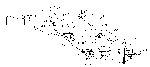
Système d'entraînement de station de triage surélevée comprenant plusieurs sections de convoyeur et servant à transporter des pièces de fabrication vers l'aval à des vitesses variables le long de plusieurs sections et entre elles, selon les instructions fournies par un système de commande. Le signal de sortie d'au moins un capteur de position de pièces de fabrication coopère avec les sections de convoyeur en amont correspondantes et fournit des données sur la position des pièces de fabrication au système de commande. Chaque section de convoyeur comporte un moyen d'entraînement à fréquence variable, et les deux entrent en prise d'entraînement à des vitesses variables. Le système de commande règle chaque moyen d'entraînement à fréquence variable de manière à interverrouiller les sections de convoyeur adjacentes pour assurer une transition douce des pièces de fabrication entre les sections de convoyeur adjacentes sans écraser ni plier les pièces de fabrication. Les différentes sections de convoyeur peuvent comprendre plusieurs convoyeurs à oreilles, qui peuvent être des convoyeurs à chaînes à oreilles.


Abrégé anglais

An elevated grade station drive system includes a plurality of conveyor sections for conveying workpieces downstream at a variable transfer speed along and between the plurality of sections according to control instructions provided by a control system. The output from at least one workpiece position sensor cooperates with corresponding upstream conveyor sections and provides workpiece position data to the control system. Each conveyor section has a corresponding variable frequency drive cooperating in variable speed driving engagement therewith. The control system controls each variable frequency drive so as to interlock adjacent conveyor sections for smooth translation of the workpieces between adjacent conveyor sections without crushing or binding the workpieces. The plurality of conveyor sections may include a plurality of lugged conveyors, which may be lugged chains.

Revendications

Note : Les revendications sont présentées dans la langue officielle dans laquelle elles ont été soumises.


WHAT IS CLAIMED IS:
1. A material handling system comprising:
a plurality of conveyor sections for conveying workpieces downstream at a
variable
transfer speed along and between said plurality of sections according to
control
instructions provided by a control system, wherein output from at least one
workpiece
position sensor cooperates with corresponding upstream conveyor sections of
said
plurality of conveyor sections and provides workpiece position data to said
control
system,
wherein each conveyor section of said plurality of conveyor sections has a
corresponding variable frequency drive cooperating in variable speed driving
engagement therewith,
said control system controlling each said variable frequency drive by said
control
instructions so as to positionally interlock adjacent conveyor sections of
said plurality
of conveyor sections to thereby control the relative position of each said
variable
frequency drive for smooth translation of the workpieces between said adjacent
conveyor sections without crushing or binding the workpieces between said
adjacent
conveyor sections,
wherein said plurality of conveyor sections include a plurality of workpiece
inspection
conveyor sections for the simultaneous inspection of workpieces fed from an
infeed
section of said plurality of conveyor sections, wherein workpiece diverting
means are
provided for diverting workpieces from said infeed section to disperse said
workpieces
for inspection along said plurality of workpiece inspection conveyor sections,
11

wherein said workpiece diverting means include a lugged inclined conveyor
section for
transporting workpieces from said infeed conveyor section to and past
selectively
actuable workpiece flow diverters for selectively diverting workpieces
according to
said control instructions to said plurality of said inspection conveyor
sections so as to
divide an infeed piece rate of said infeed conveyor section by the number of
said
inspection conveyor sections to thereby reduce the workpiece flow rate of
workpieces
on each workpiece inspection conveyor of said plurality of workpiece
inspection
conveyors.
2. The system of claim 1 wherein said workpieces are lumber to be graded and
said
plurality of workpiece inspection conveyor sections convey the lumber past
corresponding lumber grading stations.
3. The system of claim 1 wherein a workpiece collection conveyor section
downstream of
said plurality of workpiece inspection conveyors cooperates with so as to
collect the
workpieces from said inspection conveyors and delivers the workpieces to an
outfeed
conveyor section.
4. The system of claim 3 wherein said inspection conveyors are substantially
horizontal
and said collection conveyor section is inclined.
5. The system of claim 4 wherein said inspection conveyors operate in
parallel, and the
workpieces are fed in serially on said infeed conveyor section and said
inclined
conveyor section, and are collected and fed out serially from said inspection
conveyors.
6. A material handling system comprising:
a plurality of conveyor sections for conveying workpieces downstream at a
variable
transfer speed along and between said plurality of sections according to
control
12

instructions provided by a control system, wherein output from at least one
workpiece
position sensor cooperates with corresponding upstream conveyor sections of
said
plurality of conveyor sections and provides workpiece position data to said
control
system,
wherein each conveyor section of said plurality of conveyor sections has a
corresponding variable frequency drive cooperating in variable speed driving
engagement therewith,
said control system controlling each said variable frequency drive by said
control
instructions so as to positionally interlock adjacent conveyor sections of
said plurality
of conveyor sections to thereby control the relative position of each said
variable
frequency drive for smooth translation of the workpieces between said adjacent
conveyor sections without crushing or binding the workpieces between said
adjacent
conveyor sections,
wherein said at least one workpiece position sensor includes a workpiece
position
sensor for each conveyor section of said plurality of conveyor sections, and
wherein
corresponding workpiece position data is used by said control system to
control each
corresponding said variable speed drive so as to interlock said adjacent
conveyor
sections as conveyor translation speed of said plurality of conveyor sections
increases
or decreases according to said control instructions from the control system,
wherein said plurality of conveyor sections include a plurality of workpiece
inspection
conveyor sections for the simultaneous inspection of workpieces fed from an
infeed
section of said plurality of conveyor sections, wherein workpiece diverting
means are
provided for diverting workpieces from said infeed section to disperse said
workpieces
for inspection along said plurality of workpiece inspection conveyor sections,
13

wherein said workpiece diverting means include a lugged inclined conveyor
section for
transporting workpieces from said infeed conveyor section to and past
selectively
actuable workpiece flow diverters for selectively diverting workpieces
according to
said control instructions to said plurality of said inspection conveyor
sections so as to
divide an infeed piece rate of said infeed conveyor section by the number of
said
inspection conveyor sections to thereby reduce the workpiece flow rate of
workpieces
on each workpiece inspection conveyor of said plurality of workpiece
inspection
conveyors.
7. The system of claim 6 wherein said workpieces are lumber to be graded and
said
plurality of workpiece inspection conveyor sections convey the lumber past
corresponding lumber grading stations.
8. The system of claim 6 wherein a workpiece collection conveyor section
downstream of
said plurality of workpiece inspection conveyors cooperates with so as to
collect the
workpieces from said inspection conveyors and delivers the workpieces to an
outfeed
conveyor section.
9. The system of claim 8 wherein said inspection conveyors are substantially
horizontal
and said collection conveyor section is inclined.
10. The system of claim 9 wherein said inspection conveyors operate in
parallel, and the
workpieces are fed in serially on said infeed conveyor section and said
inclined
conveyor section, and are collected and fed out serially from said inspection
conveyors.
14

Description

Note : Les descriptions sont présentées dans la langue officielle dans laquelle elles ont été soumises.


CA 02469544 2004-05-31
ELEVAp EDGlZJ~DE SI'A.TI N DRIVE SY,3'1'F'M
Field of the Invention
The present invention relates gerierally to variabie frequency drives and more
specifically it relates to a material handling systern with electronic
interlock of position for
multiple variable speed drives fer contaolling the relative po!--,ition ~af
the variable speed drives
where the relative position varies, as the system speed changes.
Background of the Invention
lt can be appreciateci that variable frequency crives have been in use for
years.
Typically, variable frequency drives arL; comprised of mechanically linked
systems.
The main problem with conventional variable irequency drives is controlling
system speed changes in mec~ganically laj:rked systems. A. riother problem
with conventional
variable frequency drives are tuning of gearing between drives for each
selected speed.
another problem with conventional variable frequency drives is that
mechanically linked
systems generaliy require the purge of all material in the system prior to
changing speed to
avoid system crashes (for exaripie boards being pinched or crushed between
improperly
meshing lugs on adjacent conveyors) or errors in rnateria[ routing. Another
problem with
mechanically linlced systems is that portions of the system ca.ni-iot be
deactivated without
physicaily removing mechanical links such as sprockets, chairis, or belts.
The present invention siibstantial'.!y departs frcrn the conventional concepts
and
designs of the prior art so as to provide, an apparatus primarily developed
for the purpose of
controlling the relative position of variable speed drives where the relative
posit-ion varies as
the systern speed changes. In addition, the present invention allows the
electronic disabling of
a section o-f the system dvhile stili properly routing the entr ainec.
material to the remaining
1

CA 02469544 2004-05-31
active section of the systern as well as maintaining the correct relative
positional relationships
between adjacent conveyors and the like for proper handling of the i-,ntrained
material.
Summary of the Invention
In view of the i'oregoing disadvaptages inherent in the kTiow types of
variable
frequency drives now present in the prior art, the present invention provides
a new material
handling system with electronic interlock of position for multiple variable
speed drives
wherein the same can be utilized for controlling the relative position of
variable speed drives
where the relative position varies as the system speed cilanges.
The present indre:tition may include materia:1 position sensors on some or on
each of the variable frequency drives. The position output of the sensors is
used by a control
system to control the variable s~equency drive attached to eacll section such
that the position of
each drive correctly interlocks its conveyor and lugs with acijacent conveyors
and lugs at each
material location as the syste~r speed ramps up or down or remains constant.
The position
sensors information is also used by the control system to maintain the proper
material position
as sections of the system are disabled.
One embodiment of the invention is set out below in detail. It is to be
understood however that the invention is nol: limited in its application to
the details of
construction and to the arrangements of the components set forth in the
following description
or illustrated in the drawings. The inwention is capable of other embodiments
and of being
practiced and carried out in various ways. Also, it is to be understood that
the phraseology and
terminology employed herein are for the purpose of the description and should
not be regarded
as limiting.
2

CA 02469544 2005-12-12
It is merely one object of the present invention to provide a material
handling
system with electronic interlock of position for multiple variable speed
drives that
synchronizes grading stations with an infeed elevator and lugged incline
transfer.
Another object is to provide for one or two of the grading stations being
disabled, while enabling the system to electronically control the position of
the remaining
material handling drives such the material is properly presented to the active
sections of the
conveyance system in time or in phase.
To the accomplishment of the above and related objects, this invention may be
embodied in the form illustrated in the accompanying drawings, attention being
called to the
fact, however, that the drawings are illustrative only, and that changes may
be made in the
specific construction illustrated.
In summary, the elevated grade station drive system according to one
embodiment of the present invention may be characterized as a material
handling system
which includes a plurality of conveyor sections for conveying workpieces
downstream at a
variable transfer speed along and between the plurality of sections according
to control
instructions provided by a control system. The output from at least one
workpiece position
sensor cooperates with corresponding upstream conveyor sections and provides
workpiece
position data to the control system. Each conveyor section has a corresponding
variable
frequency drive cooperating in variable speed driving engagement therewith.
The control
system controls each variable frequency drive so as to interlock adjacent
conveyor sections for
smooth translation of the workpieces between adjacent conveyor sections
without crushing or
binding the workpieces. The plurality of conveyor sections may include a
plurality of lugged
conveyors, which may be lugged chains.
Workpiece position sensors may be provided for each conveyor section. The
corresponding workpiece position data is used by the control system to control
each
3

CA 02469544 2004-05-31
corresponding variable speed cirive so as to interlock tl-ie adjacent conveyor
sections as
conveyor translation speed increases or decreases according to the control
instructions from
ithe control system.
The plurality of conveyor sections may h;clhade a plurality of workpiece
inspection conveyor sections for the simultaneous inspection of workpieces fed
from an infeed
section. Workpiece diverting means are provided for diverting workpieces from
the infeed
section to disperse the workpieces for inspection along the plurality of
workpiece inspection
conveyor sections. The workpiece diverting means may include a lugged inclined
conveyor
section for transporting workpieces from the infeed conveyor sectior ~ to and
past selectively
actuable workpiece flow diverters for selectively diverting workpieces
according to the control
instructions of the control syutern. to the plurality of inspection conveyor
sections so as to
divide the infeed piece rate of the infeed conveyor section by the nuniber of
the inspection
conveyor sections. The workpiece flow rate of workpieces on each workpiece
inspection
conveyor is thereby reduced. A workpiece collection conveyor section downs-
;rearn of the
plurality of workpiece inspection conveyors cooperates with so as to collect
the workpieces
from the inspection conveyors and delivers t~.e workpieces to ap. outfeed
conveyor section.
In the illustrated embodimeiat, the workpieces are lumber to be graded and the
plurality of workpiece inspection conveyor sections convey the lumber past
corresponding
lumber grading stations.
The inspection corsveyors may operate in parallel. rChe workpieces may be fed
in serially on the infeed conveyor section and the inclined conveyor section.
T'hey may be
collected and fed out serially froFc~~ the inspection conveyors.
4

CA 02469544 2004-05-31
Brief Description of tbe Dra-~yi~s~~s
In the accompanying drawings like referenct characters designate the same or
similar parts throughout the several views. The present invention will be
described in detail
using the material handling system of a modern lumber R-nanufacturing planer
mill as an
exarn-ple.
Figure i is, in side elevation, partially cut away view, a series of elevated
grade
stations in a lumber manufactur?-ng planer mill configuratiori..
Figure 1 a is a schematic side elevation view os tbe present invention
installed in
a lumber manufacturing planer r-iill configuration.
Figure 2 is a diagrammatic simplified view oz=` the downstream hand off from a
grade station conveyor to an out:::eed transier corrveyor.
Figure 3 is an enlarged view of a portion of Figure 1.
Figure 4 is a diagrammatic view of incorrect positioning of the outfeed from a
grading station.
Figure 4a is an erjlarge view oi a portion of Figure 4.
Figure 5 is a diagrammatic view of correct positioning of the outfeed of
boards
from a grading station.
Figure 6 is a diagrarnrnatic 'view of the result of incorrect positioning of
lugs on
the infeed conveyor to a gradirg station 1:ransf~r resulting in a board not
beirig placed fiilly
within a iug spacing.
5

CA 02469544 2004-05-31
Figure 7 is a diagra~.rnatic view of Figure 6 showing a board being correctly
placed into the lug spacing on, agrading station transfe# .
Figure 8 is a cont, ol system block diagram.
Detailed Description of Embodiments of the lnvention
Turning now descriptiveiy to the drawings, in -whizh, as stated above, similar
reference characters denote simi:iar elerne-ats throughout the several views,
the attached figures
illustrate one embodiment of a material handling system 1 D using electronic
interlocking of
material position. Position output inforrAlation of position sensors (not
showri) is used by a
control system 12 to control variable frequency drives rrounted to
corresponding conveyor
sections 16a-16e such that the position of each drive and conveyor provides
for interlocking
hand-off of material, for example boards 18, between adjunction conveyors at
each of the
board hand-off locations 20a-20d as the system speed ramps up or clown or
remains constant.
Figure 1 is adiagranl representing the flow of material in the example of a
lumber manufacturing planer mill having in the illustrated exarr.ple, three
grading Stations
22a-22c. With ali three grading stations active, hoards 18 enter on the infeed
transfer 16a and
are divided equally to the three grade stations,. For exarrrple if 120 pÃeces
of material per
minute enter the system ther_ eac'ri grade station will get 40 pieces per
minute evenly spaced so
a grader person standing at each. grading station adjacent the corr.esponding
board turner 24a-
24c can process the pieces at a lower rate. The lugged endless eonveyor of
infeed elevator 16b
carries boards 18 on lugs 17 in direction A to the station divvrters 26a-26c.
Diverters 26a-26c
pivot on pins or shafts 28 by the actuation of cylinders 30. The diverters
route the segregated
boards in direction B past the individual grade stations on conveyors 16e,
urged by lugs 27a.
rChe material then is collected by inclined transfer 32 on lugs 34 arLd
carried in di-rection D to
the skils-a-lug transfer 36 and is kept separated and deposi_tcd in individual
locations on the
6

CA 02469544 2004-05-31
conveyance system. The graded luinber is further processed through the systeni
and finally
routed to a sorter. In particular, boards 18 are conveyed irl direcLion C from
handoff 20c to
handoff 20d by upper and lower belts 36a and 36b. Belt 380, a'ias lugs 39.
The controi of rclative position of variable speecl drives where the relative
position varies as the system speed changes has been a difficult problem to
solve with
mechanically linked systems. Such mechanically linked systems require fine
tuning of the
"gearing" between drives for each selected speed. In addition, such systems
rrtay, require the
purge of all material in the systeirt prior too changing speed to avoid system
crashes (such as
seen in Figures 4 and 4a) or er rors in material routing. This inve.titiora
provides a solution to
this problem by placing a position sensor on each drive, and using the
position output of these
sensors to control the variable frequency drive attached to each section such
that the position
of each drive correctly matches the required positions at the boards and lugs
(such as seen in
Figure 5) at each handoff location as the system speed ramps up ol- dow-ci or
remains constant.
Correct positioning of the conveyors is further xplained b" reference to -
Figures 6 and 7 for
the hand off of the boards 18 from infeed transfer 16a in Fig-tUre 1 to Grade
Transfers 16e.
Figure 7 shows the position relationship between the transfers for successful
handoff. The board must end up in the correct space for reasons of the control
system tracking
board specific grade information as the board as conveyed fro:rn th,,- infeed
through the system
and finally arriving in the correct bin in the sorter.
Another exarnpie of correci: positioning is shown in Figure 5 where the board
is
transferred from the grade transfer 16e, via transfers 38b, to the incline
transfer 32. Figure 5
shows the correct positioning for successful hand off. Figures 4 and 4a show
pinching or
crushing of the board between mis-timed lugs.
The multiple inc~lined lumber grading statio'n sysl:-.em as an e)(arnple of
the
invention invo:tves the use of ~ve variable frequency drives: one for the
sorter drive, one for
7

CA 02469544 2004-05-31
the skip a lug drive, and tlu=ee grading station drives, ihat iis, one for
each individual grading
station. The infeed elevator conveyance drive "! 4b may be nnechanically
linked to the skip-a-
lug drive 14f, or may be driven with an alternative positiori locked variable
fresluency drive.
Figure 8 shows the gea~eral =4rra.~~.gerrient of the position control loops
for each. drive. The
sorter drive 14g is controlled to a speed by the PLC control systeni 12a. The
position sensor
inforrriation from the sorter 40 is fed to the motion controller 12b and is
corn.pai=ed to the skip-
a-lug transfer position 36 to yprovide the signal that drives the skip-a-lug
variable frequency
drive 14f.
1 G A position sensox feedback is used with each of the above mentioned
drives. A
motion controller 12b uses these sensor signaas to control the speed and
position of the skip-a-
lug and grade station variable frequency drive s A 4c-14f) and their
associated lugged transfers.
The timing for the whole systerri is based on the position sensor oj^the
sorter drive. The skip-
a-lug drive synchronizes speed and position with the sorter drive. The skip.-a-
lug variable
frequency drive drives the infeed elevator translcr and the lugged incline
transfer. Each of the
grading station drives is synchronized to the speed arsd position of the skip-
a-lug drive. The
grading stations are therefore synchronized with the infeed elevator and
lugged incline
transfer. As the sorter drive, changes speed, the skip-a-lug drive changes
speed to stay
synchronized with the sorter dr~.ve. In the event that the skip-a-lag drive
needs to create an
empty lug space for a cut-in-two board, the skip-a-lug drive slows down
momentarily relative
to the sorter drive. This creates an empty iug space. T1-1_e grade station
drives follow the
position and speed of the skip-a-lug drive daxrlng this speed change so that
the system, stays
synchronized.
The infeed elevator introduces the boards into the multiple grading station
transfers. The system is designed sucb that tbis infeed rate of boa:rds is
separated equally in_to
the nurnber of grading stations that are available to accept the material. For
example, if the
infeed elevator 16b has a product rate of one hundred twenty boards per
minute, and there are
three grading station conveyors 16a-16c able to accept boards 18, each grading
station 22a-22c
8

CA 02469544 2004-05-31
will process forty boards 18 per minute. The lugged incline t-ransfer 32
removes the boards 18
from the grading station transfers 1 Sa-1 bc. The total number of grade
stations that are able to
accept boards car~ be modified tc suit operating conditions. Due to the fact
that each grading
station transfer is synchronized with the infeed elevator, the i:iming
relationship must change to
suit the total nunlber of grading stations that are accepting boards. The
motion controller uses
the position sensors mounted on each oE'the grading station transfers to set
the timing positions
and speeds for all combinations of available grading statior~s. When a grading
station is put
off-line, the motion controller parlcs its transfers so that their lugs will
not interfere with the
transport of boards on the skip-a-lug incline transfer.
The use of lugged transfers as the conveyance means is described here as a
means of describing the invention, other coaaveyance ::neans are possible and
included in the
invention. Such other conveyance means could include smooth c}iains, belts,
and others well
lcnown in the art.
With respect to the above description then, it is to be realized that the
optimum
dimensional relationships for the parts of the invention, to irtelude
variations in size, materials,
shape, form, function and manner of operation, assembly and use, are deemed
readily apparent
and obvious to one skilled in the art, and all equivalent relationships to
those illustrated in the
drawings and described in the specification are intended to be encompassed by
the present
invention.
Therefore, the foregoing is considered as illustrative only of thie principles
of
the invention. Further, since numerous rnodifications and changes will readily
occur to those
skilled in the art, it is not desired to limit the invention to the exact
construction and operation
shown and described, and accordingly, all suitable modi Fica.tions and
equivalents may be
resorted to, falling within the scope of the invention.
~

CA 02469544 2004-05-31
As will be apparenL to those skilled in the art in the light of the foregoing
disclosure, many alterations and modifications are possible in the practice of
this invention
without departing from the spirit or scope thereof. Accordingly, the scope of
the invention is
to be construe& in accordance with the substance defined by ti-ie following
claims.
?~

Dessin représentatif
Une figure unique qui représente un dessin illustrant l'invention.
États administratifs

2024-08-01 : Dans le cadre de la transition vers les Brevets de nouvelle génération (BNG), la base de données sur les brevets canadiens (BDBC) contient désormais un Historique d'événement plus détaillé, qui reproduit le Journal des événements de notre nouvelle solution interne.

Veuillez noter que les événements débutant par « Inactive : » se réfèrent à des événements qui ne sont plus utilisés dans notre nouvelle solution interne.

Pour une meilleure compréhension de l'état de la demande ou brevet qui figure sur cette page, la rubrique Mise en garde , et les descriptions de Brevet , Historique d'événement , Taxes périodiques et Historique des paiements devraient être consultées.

Historique d'événement

Description Date
Le délai pour l'annulation est expiré 2023-11-30
Lettre envoyée 2023-05-31
Lettre envoyée 2022-11-30
Requête pour le changement d'adresse ou de mode de correspondance reçue 2022-10-31
Inactive : Transferts multiples 2022-10-31
Lettre envoyée 2022-05-31
Lettre envoyée 2021-11-29
Demande visant la nomination d'un agent 2021-11-05
Inactive : Transferts multiples 2021-11-05
Demande visant la révocation de la nomination d'un agent 2021-11-05
Inactive : Transferts multiples 2021-10-25
Représentant commun nommé 2019-10-30
Inactive : Regroupement d'agents 2015-05-14
Exigences relatives à la révocation de la nomination d'un agent - jugée conforme 2012-07-31
Inactive : Lettre officielle 2012-07-31
Exigences relatives à la nomination d'un agent - jugée conforme 2012-07-31
Demande visant la révocation de la nomination d'un agent 2012-07-16
Demande visant la nomination d'un agent 2012-07-16
Accordé par délivrance 2009-03-24
Inactive : Page couverture publiée 2009-03-23
Inactive : Lettre officielle 2009-01-21
Un avis d'acceptation est envoyé 2009-01-20
Demande visant la révocation de la nomination d'un agent 2009-01-13
Demande visant la nomination d'un agent 2009-01-13
Inactive : Approuvée aux fins d'acceptation (AFA) 2008-12-08
Lettre envoyée 2008-12-04
Exigences relatives à la nomination d'un agent - jugée conforme 2008-10-10
Exigences relatives à la révocation de la nomination d'un agent - jugée conforme 2008-10-10
Inactive : Lettre officielle 2008-10-10
Demande visant la nomination d'un agent 2008-10-10
Demande visant la révocation de la nomination d'un agent 2008-10-10
Lettre envoyée 2008-10-06
Préoctroi 2008-09-16
Retirer de l'acceptation 2008-09-16
Requête en rétablissement reçue 2008-09-16
Taxe finale payée et demande rétablie 2008-09-16
Inactive : Correspondance - Transfert 2008-09-16
Réputée abandonnée - les conditions pour l'octroi - jugée non conforme 2008-09-10
Demande visant la révocation de la nomination d'un agent 2008-09-09
Demande visant la nomination d'un agent 2008-09-09
Demande visant la révocation de la nomination d'un agent 2008-07-25
Inactive : Correspondance - Transfert 2008-07-25
Demande visant la nomination d'un agent 2008-07-25
Demande visant la révocation de la nomination d'un agent 2008-07-24
Demande visant la nomination d'un agent 2008-07-24
Un avis d'acceptation est envoyé 2008-03-10
Lettre envoyée 2008-03-10
Un avis d'acceptation est envoyé 2008-03-10
Inactive : Approuvée aux fins d'acceptation (AFA) 2008-01-02
Modification reçue - modification volontaire 2007-07-13
Lettre envoyée 2007-04-03
Inactive : Dem. de l'examinateur par.30(2) Règles 2007-01-16
Lettre envoyée 2006-09-19
Lettre envoyée 2005-12-15
Requête d'examen reçue 2005-12-12
Exigences pour une requête d'examen - jugée conforme 2005-12-12
Toutes les exigences pour l'examen - jugée conforme 2005-12-12
Modification reçue - modification volontaire 2005-12-12
Inactive : Lettre officielle 2005-10-19
Lettre envoyée 2005-10-18
Inactive : Correspondance - Transfert 2005-09-06
Demande publiée (accessible au public) 2004-11-30
Inactive : Page couverture publiée 2004-11-29
Inactive : CIB en 1re position 2004-11-17
Inactive : CIB attribuée 2004-11-17
Lettre envoyée 2004-09-14
Inactive : Transfert individuel 2004-08-10
Inactive : Certificat de dépôt - Sans RE (Anglais) 2004-07-09
Demande reçue - nationale ordinaire 2004-07-08

Historique d'abandonnement

Date d'abandonnement Raison Date de rétablissement
2008-09-16
2008-09-10

Taxes périodiques

Le dernier paiement a été reçu le 2008-05-30

Avis : Si le paiement en totalité n'a pas été reçu au plus tard à la date indiquée, une taxe supplémentaire peut être imposée, soit une des taxes suivantes :

  • taxe de rétablissement ;
  • taxe pour paiement en souffrance ; ou
  • taxe additionnelle pour le renversement d'une péremption réputée.

Les taxes sur les brevets sont ajustées au 1er janvier de chaque année. Les montants ci-dessus sont les montants actuels s'ils sont reçus au plus tard le 31 décembre de l'année en cours.
Veuillez vous référer à la page web des taxes sur les brevets de l'OPIC pour voir tous les montants actuels des taxes.

Titulaires au dossier

Les titulaires actuels et antérieures au dossier sont affichés en ordre alphabétique.

Titulaires actuels au dossier
USNR KOCKUMS CANCAR HOLDINGS ULC
Titulaires antérieures au dossier
DANNY C. WHITE
DARREN A. ROSS
DARRYL IRWIN KUJAT
EDWARD K. APTED
GEOFF DAVID WIGHT
Les propriétaires antérieurs qui ne figurent pas dans la liste des « Propriétaires au dossier » apparaîtront dans d'autres documents au dossier.
Documents

Pour visionner les fichiers sélectionnés, entrer le code reCAPTCHA :


Pour visualiser une image, cliquer sur un lien dans la colonne description du document. Pour télécharger l'image (les images), cliquer l'une ou plusieurs cases à cocher dans la première colonne et ensuite cliquer sur le bouton "Télécharger sélection en format PDF (archive Zip)" ou le bouton "Télécharger sélection (en un fichier PDF fusionné)".

Liste des documents de brevet publiés et non publiés sur la BDBC .

Si vous avez des difficultés à accéder au contenu, veuillez communiquer avec le Centre de services à la clientèle au 1-866-997-1936, ou envoyer un courriel au Centre de service à la clientèle de l'OPIC.


Description du
Document 
Date
(aaaa-mm-jj) 
Nombre de pages   Taille de l'image (Ko) 
Description 2004-05-30 10 745
Abrégé 2004-05-30 1 43
Dessins 2004-05-30 7 266
Revendications 2004-05-30 4 224
Dessin représentatif 2004-11-17 1 21
Description 2005-12-11 10 724
Revendications 2005-12-11 4 178
Abrégé 2005-12-11 1 28
Revendications 2007-07-12 4 153
Dessin représentatif 2009-03-12 1 18
Certificat de dépôt (anglais) 2004-07-08 1 158
Courtoisie - Certificat d'enregistrement (document(s) connexe(s)) 2004-09-13 1 129
Accusé de réception de la requête d'examen 2005-12-14 1 176
Rappel de taxe de maintien due 2006-01-31 1 111
Avis du commissaire - Demande jugée acceptable 2008-03-09 1 164
Avis de retablissement 2008-12-03 1 170
Courtoisie - Lettre d'abandon (AA) 2008-12-02 1 166
Avis du commissaire - Non-paiement de la taxe pour le maintien en état des droits conférés par un brevet 2022-07-11 1 543
Courtoisie - Brevet réputé périmé 2023-01-10 1 537
Avis du commissaire - Non-paiement de la taxe pour le maintien en état des droits conférés par un brevet 2023-07-11 1 540
Correspondance 2005-10-18 1 14
Taxes 2006-01-29 1 38
Taxes 2007-04-18 1 37
Taxes 2008-05-29 1 36
Correspondance 2008-07-24 5 150
Correspondance 2008-07-23 6 194
Correspondance 2008-10-09 1 18
Correspondance 2008-10-09 1 20
Correspondance 2008-10-09 5 177
Correspondance 2008-09-08 5 175
Correspondance 2009-01-20 1 18
Correspondance 2009-01-12 5 191
Correspondance 2009-01-12 6 218
Taxes 2009-05-28 1 201
Correspondance 2012-07-15 6 273
Correspondance 2012-07-30 1 14
Correspondance 2012-07-30 1 22