Note : Les descriptions sont présentées dans la langue officielle dans laquelle elles ont été soumises.
CA 02472076 2004-09-23
I
- 1 -
TISSUE GRASPERISUTURE PASSER INSTRUMENT
Technical Field
The field of art to which this invention relates is surgical instruments, in
particular, surgical instruments for use in minimally invasive surgical
procedures.
Background of the Invention
Minimally invasive surgical procedures have proven to be of significant
benefit to patients. Typically, in a minimally invasive procedure, a surgical
site is
accessed using a small incision through a patient's skin and underlying
fascia. A
conventional trocar cannula may be inserted through the incision to provide a
passageway for instruments, scopes, etc. The surgeon may view the operative
site
remotely or by direct visualization. Many instruments have been developed for
minimally invasive surgical procedures including endoscopic and arthroscopic
instruments. Arthroscopic instruments that are known and used include, for
example, conventional arthroscopic scissors, arthroscopic fastener appliers,
and
arthroscopic suture passers.
Of particular importance in this art are instruments and methods for applying
surgical sutures in an arthroscopic procedure. In an open procedure, the
surgeon
typically holds a surgical needle in a needle grasper and pushes and pulls the
surgical
needle through tissue around a tissue site and releases and re-grasps the
needle
each time the needle is exits the tissue that is required to be approximated.
This type
of open suturing technique is difficult to perform successfully in an
arthroscopic
procedure because of the limited working space. Specially designed
arthroscopic
suture devices have been developed to remotely pass sutures through tissue in
arthroscopic procedures.
MIT-5002
CA 02472076 2004-09-23
2 -
Although the arthroscopic suture passers of the prior art are adequate for
their
intended purpose, there is a constant need in this art for new instruments
having
advantageous characteristics and features that are easy to use in an
arthroscopic
surgical procedure.
Summary of the Invention
Therefore, it is an object of the present invention to provide novel surgical
instruments for arthroscopic surgical instruments that advantageously pass
suture in
arthroscopic surgical procedures.
Accordingly, a novel suture passer instrument is disclosed. The suture passer
instrument has a frame having a proximal end and a distal end. The frame has a
longitudinal passage. A bottom jaw member is mounted to the distal end of the
frame.
The bottom jaw member has a top surface and a bottom surface. There is a
needle
passageway in the bottom jaw member having a distal opening out through the
top
surface of the bottom jaw and a proximal opening in communication with the
longitudinal passage of the frame. A top jaw member is pivotally mounted to
the distal
end of the frame such that the top jaw member is moveable with respect to the
bottom
jaw member. The top jaw member having a distal opening for receiving a
cartridge
member. A handle member is mounted to the proximal end of the frame. The
handle
member has a cavity. There is a jaw actuation member having a top end and a
bottom end, wherein the top end of the jaw actuation member is mounted to the
handle member. There is also a needle rod driving trigger member having a top
and a
bottom, wherein the top of the needle rod driving member is pivotally mounted
to the
handle member. A jaw actuation rod having a proximal end a distal end is
slidably
mounted in the passage of the frame. The distal end of the jaw actuation rod
operably
engages the top jaw member, and the proximal end of the actuation rod is
mounted to
the jaw actuation member. A needle driving rod is slidably mounted to the
frame. The
MIT-5002
CA 02472076 2004-09-23
3 -
needle driving member has a proximal end mounted to the needle driving trigger
and a
distal end for engaging a surgical needle mounted in the needle passageway.
Yet another aspect of the present invention is a suture passer instrument. The
suture passer instrument has a frame having a proximal end and a distal end.
The
frame has a longitudinal passage. A bottom jaw member is mounted to the distal
end
of the frame. The bottom jaw member has a top surface and a bottom surface.
There
is a needle passageway in the bottom jaw member having a distal opening out
through the top surface of the bottom jaw and a proximal opening in
communication
with the longitudinal passage of the frame. A top jaw member is pivotally
mounted to
the distal end of the frame such that the top jaw member is moveable with
respect to
the bottom jaw member. The top jaw member having a distal opening for
receiving a
cartridge member. A handle member is mounted to the proximal end of the frame.
The handle member has a cavity. There is a jaw actuation member having a top
end
and a bottom end, wherein the top end of the jaw actuation member is mounted
to the
handle member. There is also a needle rod driving trigger member having a top
and
a bottom, wherein the top of the needle rod driving member is pivotally
mounted to the
handle member. A jaw actuation rod having a proximal end a distal end is
slidably
mounted in the passage of the frame. The distal end of the jaw actuation rod
operably engages the top jaw member, and the proximal end of the actuation rod
is
mounted to the jaw actuation member. A needle driving rod is slidably mounted
to the
frame. The needle driving member has a proximal end mounted to the needle
driving
trigger and a distal end for engaging a surgical needle mounted in the needle
passageway. The instrument has a removable cartridge member mounted in the
opening of the top jaw member. The cartridge member has a cavity for receiving
and
engaging at least part of a surgical needle.
Yet another aspect of the present invention is a method of using the above-
described suture passer instruments of the present invention in a surgical
procedure to
pass a surgical needle and attached suture through tissue.
MIT-5002
CA 02472076 2010-09-02
- 3a -
In a further aspect a suture passer instrument, comprising:
a frame having a proximal end and a distal end, said frame having a
longitudinal passage;
a bottom jaw member mounted to the distal end of the frame, the bottom jaw
member having a needle passage for deceiving a surgical needle, the needle
passage having a distal opening out through the top of the bottom jaw member
and a
proximal opening in communication with the longitudinal passage of the frame;
a top jaw member pivotally mounted to the distal end of the frame such that
the
top jaw member is moveable with respect to the bottom jaw member, said top jaw
member having a distal opening for receiving a cartridge member;
a handle member mounted to the proximal end of the frame, the handle
member having a cavity;
a jaw actuation member having a top end and a bottom end, wherein the top
end of the jaw actuation member is mounted to the handle member;
a needle rod driving member having a top and a bottom;
a jaw actuation rod having a proximal end and a distal end, wherein the jaw
actuation rod is slidably mounted in the passage of the frame and wherein the
distal
end of the jaw actuation rod engages the top jaw member, and the proximal end
of
the actuation rod is mounted to the jaw actuation member; and
a needle driving rod slidably mounted to the frame, wherein the needle driving
rod has a proximal end mounted to the needle driving member and a distal end
for
engaging a needle;
wherein the needle rod driving member is a trigger member, and the top of the
needle rod driving member is pivotally mounted to the handle member; and the
instrument additionally comprises a cartridge mounted to the top jaw member,
wherein the cartridge comprises : a member having a top, a bottom and a cavity
extending there though; a top flange mounted to the cartridge having an
opening in
communication with the cavity; a bottom flange mounted to the bottom of the
member
having an opening in communication with the cavity; and, at least one needle
engagement tab member extending into the cavity.
In a further aspect use of the instrument described herein for passing suture
through
tissue.
CA 02472076 2004-09-23
4 -
These and other aspects and advantages of the present invention will become
more apparent from the following description and accompanying drawings.
Brief Description of the Drawings
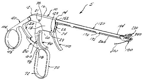
FIG. 1 is a perspective view of a grasper and needle passer instrument of the
present invention.
FIG. 2 is a side view of the tissue grasper and suture passer instrument of
FIG. 1.
FIG. 3A is a partial cross-sectional view of the proximal end of the
instrument
of FIG. 2.
FIG. 3B is a partial cross-sectional view of the distal end of the instrument
of
FIG. 2.
FIG. 4 is a magnified exploded perspective view of the distal end of the
tissue
and suture passer instrument of the present invention illustrating the upper
and lower
jaws of the instrument and a needle clip cartridge that is mounted to the
upper jaw.
FIG. 5 illustrates a surgical needle and suture prior to mounting in the lower
jaw of the instrument.
FIG. 6 illustrates the distal end of the instrument in an armed configuration
with
the needle cartridge mounted in the upper jaw and the surgical needle mounted
in the
lower jaw with the upper jaw open and ready to receive tissue.
FIG. 7 illustrates the distal end of the armed instrument in proximity to
tissue
that will be grasped and sutured.
MIT-5002
CA 02472076 2004-09-23
-
FIG. 8 is a partial side view illustrating the instrument grasping the soft
tissue
between the jaws, prior to engaging the needle.
5 FIG. 9 is a side view of the instrument illustrating the needle deployed
through
the tissue, with the distal end of the needle engaged and locked by the
cartridge in the
top jaw.
FIG. 10 is a partial transverse cross-sectional view of the instrument of FIG.
9, illustrating the needle engaged in the cartridge.
FIG. 11 is a partial longitudinal cross-sectional view of the cartridge of
FIG. 10,
illustrating the needle engaged by the cartridge.
FIG. 12 illustrates the upper jaw of the instrument rotated to the raised
position
with the needle exited from the tissue and the suture passing through the
tissue.
FIG. 13 illustrates the instrument of FIG. 12, wherein the instrument has been
pulled back away from the tissue, causing an additional length of the suture
to be
pulled or passed through the tissue.
FIG. 14. is a perspective view of the distal end of the instrument of the
present
invention after the cartridge has been removed from the upper jaw and the
needle has
been cut away from the suture.
FIG.15 illustrates the instrument of the present invention inserted into a
patient's shoulder and passing a needle and suture through the patient's
ligament
labral complex to effect a Bankart repair procedure
MIT-5002
CA 02472076 2004-09-23
6 -
FIG. 16 is a top view of an alternate embodiment of a cartridge that can be
used with the suture passer instruments of the present invention; the
cartridge has an
elongated slot for engaging a needle and a proximal opening such that the
needle can
be moved along the slot into the proximal opening and removed from the
cartridge.
FIG. 17 is a partial, cross-sectional view of the cartridge of FIG.16,
illustrating a
needle engaged in the slot.
FIG. 18 is a top view of the cartridge of FIG. 16, illustrating the distal end
of a
needle engaged in the slot.
FIG. 19 illustrates the cartridge of FIG. 18 with the needle moved along the
slot
into the proximal opening.
FIG. 20 is a cross-sectional view of the cartridge of FIG. 19 illustrating the
needle in the proximal opening in position to be removed from the cartridge.
Detailed Description of the Invention
The tissue grasper and suture passer instruments of the present invention are
preferably used in minimally invasive arthroscopic surgical procedures.
However,
these instruments may be use in other types of minimally invasive procedures
including endoscopic surgical procedures, laparoscopic surgical procedures,
etc. The
instruments may also be used in open surgical procedures. The tissue grasper
and
suture passer instruments may be constructed of conventional, biocompatible
materials that are easily cleaned and capable of being sterilized. The
materials
include but are not limited to surgical stainless steel, nitinol, titanium,
polycarbonate
and the like, and combinations thereof. The cartridges used in the tissue
grasper and
needle passer instruments of the present invention are preferably made from
conventional biocompatible polymeric materials that are readily sterilizable
including
MIT-5002
CA 02472076 2004-09-23
7 -
but not limited to polyethylene, polycarbonate, ABS and the like. The
cartridges may
also be made from the previously-mentioned metals, and combinations of metals
and
polymeric materials.
The tissue grasper and suture passer instrument 5 of the present invention is
illustrated in FIGS. 1-3. The instrument 5 is seen to have a frame member 10
having
a proximal end 12, a distal end 14, a top 16, opposed lateral sides 18 and a
bottom
20. Cavity 22 is contained within frame member 10. Cavity 22 is seen to have
distal
opening 24, bottom opening 26 and proximal opening 28. Openings 24, 26 and 28
are seen to be in communication with cavity 22. A pair of opposed trigger
pivot pin
openings 21 extend though the top of frame 10 and are in communication with
cavity
20. In addition, a pair of opposed pivot pin openings 29 extend through the
bottom of
frame 10 and are in communication with cavity 22. Frame member 10 is also seen
to
have mounting cavity 30. Extending back and angulated down from the proximal
end
12 of frame member 10 is the handle member 40. Handle member 40 is seen to
have proximal end 41 and distal end 42. Extending from proximal end 41 is the
optional finger ring 44 having opening 45. Also extending from the handle
member 40
is the locking member engagement post 50. Engagement post 50 is seen to be
preferably curved, having a proximal end 52, a distal rounded free end 54 and
a
plurality of teeth 56. The jaw actuation member 60 is seen to have upper end
62 and
lower end 64. Upper end 62 has pivot pin hole 66 extending therethrough. Lower
end
64 is seen to have pivot hole 68 extending therethrough. Extending from the
lower
end 64 of jaw actuation member 60 is the optional finger ring member 70 having
opening 72. Spring retainer cavity 74 is seen to extend into member 60 through
the
distal side 61. The jaw actuation member 60 is seen to be pivotally mounted to
frame
member 10. More specifically, upper end 62 is seen to be mounted in cavity 22
by
pivot pin 78 that extends through openings 21 in frame 10 and opening 68 in
jaw
actuation member 60.
MIT-5002
CA 02472076 2004-09-23
- 8 -
The locking member 80 is seen to be pivotally mounted to actuation member
60. The locking member 80 is seen to be an "L" shaped member having a proximal
end 82 and a distal end 88, however the member 80 may have other shapes if
desired. Extending from the top surface of the proximal end of member 80 are
the
teeth 84. Teeth 84 are engageable with teeth 56 of locking member 50. Pivot
pin
mounting hole 86 is seen to extend transversely through member 80. Mounted to
the
proximal end 88 of locking member 80 is the disengagement member 90.
Disengagement member 90 is seen to have a generally curved shape with top end
91.
bottom end 92, proximal surface 93 and distal surface 94. Disengagement member
90 is mounted to actuation member 60 by pivot mounting pin 98 that is inserted
through pivot pin mounting hole 86 and pivot pin hole 64. Helical spring 100
is seen to
be mounted in cavity 74 such that the bottom 102 of spring member 100 is in
contact
with the bottom of cavity 74, and the top 104 of spring member 100 is in
contact with
the proximal surface 93 of member 90, thus exerting a biasing force against
member
90. Also pivotally mounted in cavity 22 of frame 10 is the trigger member 110.
The
trigger member 110 is seen to have a bottom end 112, a top end 114, a proximal
surface 116 and a distal surface 118. Extending proximally from the top end
114 is
the lever member 120. Lever member 120 is seen to have second spring retention
cavity 122. Extending through the upper end 114 of trigger member 110 are the
slotted opening 125 and the pivot pin opening 127. The trigger member 110 is
seen
to be pivotally mounted in cavity 22 of frame 10 by the pivot pin 129 that
extends
through pivot pin mounting opening openings 29 in frame 10 and pivot pin
opening
127 in trigger member 110. Spring member 130 is seen to have bottom 132 and
top
134. The spring member 130 is mounted in spring retention cavity 122, and the
bottom 132 exerts a biasing force against lever member 110 through lever
member
120.
Extending from the distal end 14 of frame 10 is the elongated member 150.
Elongated member 150 is seen to have a proximal end 152, a distal end 154 and
a
longitudinal slot 156 therein extending along the length of member 150 and
having
MIT-5002
CA 02472076 2004-09-23
9 -
proximal opening 157 and distal opening 158. The elongated member 150 is seen
to
have outer surface 160 and inner surface 162, as well as top 164 and bottom
166.
The proximal end 152 of elongated member 150 is seen to be mounted in frame 10
in
cavity 30. Although it is preferred that proximal end 152 be fixedly mounted,
alternatively, the end 152 may be mounted to provide for rotational movement
or
longitudinal movement of tubular member 150. Extending downward from the outer
bottom 166 of elongated member 150 are the grommet members 170 having
longitudinal passages 172.
Referring also now to FIGS 3B and 4-15, seen to be extending from the distal
end 154 of elongated member 150 is the lower jaw member 180. The lower jaw
member 180 is seen to have proximal end 182 and distal end 184, and a pair of
opposed sides 188 and 189, top 186 and bottom 185. Lower jaw member 180 is
seen
to have cavity 190 having proximal opening 192 and top opening 194, both of
which
are in communication with cavity 190. Cavity 190 is seen to have distal end
196
adjacent to inner wall 186. The needle passage opening 187 is contained in
wall 186.
Extending transversely through jaw member 180, and in communication with
cavity
190, are the pivot pin mounting holes 188. The jaw member 180 is seen to have
top
grasping surface 200. Extending up from the surface 200 are the tissue
engagement
teeth 202 having tips 204. Surface 200 is seen to have needle opening 206.
Also
contained in the lower jaw member 180 is the needle passageway 210 having
proximal and distal ends 212 and 214, respectively. The proximal end 212 of
passageway 210 is in communication with opening 187 and the distal end 214 is
in
communication with opening 206. Preferably, the passage has an opening 218
extending out through the side 188 of jaw member 180 to facilitate the loading
and
passage of a needle and suture. The opening 218, although not preferred, may
be
located on the bottom 185 of jaw member 180. Optionally, there are multiple
openings
218. The upper jaw member 230 is seen to be pivotally mounted to lower jaw
member 180. The upper jaw member 230 is seen to have proximal end 232, distal
end 234, upper surface 236 and bottom surface 238. Extending down from the
MIT-5002
CA 02472076 2004-09-23
- 10 -
bottom surface 238 are the tissue engagement teeth 241 having tips 242.
Extending
down and proximally from distal end 232 of the upper jaw member 230 is the
camming
member 240. The camming member 240 is seen to have concave curved top
camming surface 249. Contained in surface 249 is the longitudinal retention
groove
244. The pivot hole passage 248 is seen to be contained in the bottom of the
camming member 240. The upper jaw member 230 is mounted in cavity 190 by
inserting pivot pin 235 though pivot pin openings 188 and pivot hole passage
248.
The upper jaw 230 is seen to have U-shaped slot 250 having opening 251.
Extending
up from the upper surface 236 of jaw member 230 is the cartridge retainer
member
255. Retainer member 255 is seen to have top 256 and distal ramped surface
257.
The member 255 has opposed sides 258 connected by curved ends 259.
Slidably mounted in the passages 172 of grommet member 170 is the needle
actuator rod 260. Rod 260 is seen to be an elongated rod-like member having a
proximal end 262 and a distal end 266 having a distal needle engagement nose
268.
Distal end 266 is seen to be optionally necked down and has a smaller diameter
than
that of rod 260. The proximal end 262 of rod 260 is seen to pivotally mounted
in
cavity 22 of frame 10 in slotted opening 125 in trigger member 110.
The jaw actuation rod 280 is seen to have distal end 284 and proximal end
282. The jaw actuation rod 280 is a rod-like member that is slidably mounted
in
longitudinal slot 156 of elongated member 150. The proximal end 282 of
actuation rod
282 is pivotally mounted to the top section 62 of jaw actuation member 60 by
pin
member 281 extending proximally from proximal end 282 and engaged by nub 63
extending up from the top 62 of jaw actuation member 60. Extending distally
from the
distal end 284 of actuation rod 280 is the cam member 290 having camming
surface
295. The tongue member 297 is seen to extend out from surface 295, and to be
engaged in retention groove 244 of carnming member 240.
MIT-5002
CA 02472076 2004-09-23
- 11 -
The needle cartridge 300 is seen in FIG. 4. The cartridge 300. is seen to have
member 310 having cavity 315. Although cavity 315 preferably has a circular
cross-
section as shown, the cavity 315 my have other geometric cross-sections
including but`
not limited to square, polygonal, rectangular, triangular, oval and the like
and
combinations thereof. Cartridge 300 is seen to have proximal end 302 and
distal end
304. Member 310 is seen to have top 311, bottom 312, and exterior surface 314
and
interior surface 316. Extending into the cavity 315 is the annular engagement
tab
ring member 318. Although it is preferred that the tab ring member 318 have an
annular configuration, other configurations may be used including tab
segments, or
other geometric configurations depending on the configuration of the cavity
315.
Mounted to the top 311 of cartridge 300 is the upper flange 320 having top
surface
322, bottom surface 324, proximal end 326 and distal end 329. Extending
through
flange 320 is the needle opening 327 in communication with cavity 315. Seen to
extend through the proximal end 326 of flange 320 is the retainer opening 325.
Bottom flange 330 is seen to be mounted to the bottom 312 of member 310, and
has
opening 335 in communication with cavity 315, as well as proximal end 332 and
distal
end 334. The cartridge 300 is mounted to jaw member 230 by sliding the
proximal
end 326 of flange 320 over the top surface 236 of jaw member 230 such that the
member 310 slides into slot 250, and opening 325 is engaged by retention
member
255, such that the top flange 320 is partially on top of and bottom flange 330
is
partially below upper jaw member 230.
The instrument 5 is armed for passing a needle 350 and attached suture 370
through tissue by inserting a needle 350 in needle passageway 210 of jaw
member
180. The needle 350 is seen to have distal end 354 and proximal end 352
extending
from the proximal end 352 of needle 350 is the suture 370. Extending distally
from the
distal end 354 of needle 350 is the pointed piercing end 356. Needle 356 is
seen to
have opposed undercuts 358 to facilitate locking in cavity 315 of cartridge
300. The
needle 350 is mounted in jaw member 180 such that the distal piercing end 354
extends at least partially out of passage 210 and through opening 206 and
above
MIT-5002
CA 02472076 2004-09-23
- 12 -
grasping surface 200. The needle 350 is seen to preferably have a curved
configuration to conform to the needle passageway 210, but may also be made of
a
resilient material such as spring stainless steel or a superelastic shape
memory
material such as Nitinol, and may have a substantially straight configuration.
The
cartridge 300 is then mounted to upper jaw 230 by sliding member 310 into slot
250
such that the flanges 320 and 330 are above and below the top and bottom
surfaces
of jaw member 230, and such that retainer opening 325 is engaged by retention
member 255, and thereby substantially fixed in place with respect to jaw
member 230.
The suture 370 may be mounted to needle 350 in a conventional manner,
including swaging the distal end 374 of suture in a drilled hole or channel in
the
proximal end 352 of needle 350, threading the suture 370 through an eyelet,
etc. Any
conventional sutures may be used including non-absorbable sutures made from
conventional biocompatible polymers and bio-absorbable sutures made from
conventional bio-absorbable and resorbable polymers.
When armed, the instrument 5 operates in the following manner. The surgeon
grasps the instrument 5 by the handle member 40 and places a thumb within
opening
45 of thumb ring 44. One or more of the other fingers of the hand are placed
through
opening 72 of finger loop 70. Tissue 500 is grasped between the upper jaw
member
230 and the lower jaw member 180 by pulling back on the actuation member 60
causing the actuation member 60 to pivot about pivot pin 78 causing jaw
actuation rod
280 to be displaced distally in the slot 157 of elongated member 150. This
causes the
camming member 290 of actuation rod 280 to engage the camming surface 242 of
camrning member 240, thereby causing the jaw member 230 to rotate about pivot
pin
235 toward lower jaw member 180. The opposite rotation of the jaw actuation
member 60 causes the actuation rod 280 to slide and move proximally causing
the top
jaw to rotate open. The tissue 600 is engaged by teeth 202 extending from the
upper
surface 200 of jaw member 180 and the teeth 241 extending downward from the
bottom surface 238 of jaw member 230. The tissue 500 is also partially pierced
by the
MIT-5002
CA 02472076 2004-09-23
- 13 -
piercing point 356 of needle 350. The spatial position of jaw 180 relative to
jaw 230 is
maintained by the locking member 80 and the engagement post 50 which are
engaged by the teeth 56 and 84 in a ratcheting manner. The needle 350 and
suture
370 are passed through tissue 600 by the surgeon engaging or pulling back on
trigger
member 110 thereby rotating the trigger member 110 about pivot pin 129. This
is
seen to cause the actuation rod 260 to move distally through the passages 172
of
grommet members 170. The needle engagement nose 268 of distal end 266 then
engages the distal end 352 of needle 350 pushing it through 210, and out
through
opening 206, through tissue 500 and into passage 315 of member 310 of
cartridge
300 and partially out through opening 327 such that the undercuts 358 are
engaged
by the ring tab member 318. Next the surgeon opens jaw 230 by first unlocking
the
jaw 230 by pulling back on disengagement member 90 causing locking member 80
to
disengage from engagement post 50, and then moving finger loop 70 distally to
rotate
the jaw 230 open. This causes the needle 350 to move completely through tissue
600
and move the suture 370 through tissue 500. The surgeon then cuts the suture
370
away from needle 350 and cartridge 300, completing the passage of the suture
370
through the tissue 600. If desired, the instrument 5 can be re-armed with a
new
needle 350 and attached suture 370 along with a new cartridge 300 to provide
for
multiple suture passes.
In an alternate embodiment of the cartridge 300 of the present invention is
seen in FIGS. 15-20. The cartridge 500 is seen to have a member 510 having a
cavity 515. Cavity 515 has an elongated slot section 520 communicating with a
proximal circular opening 522. Opening 522 may have other geometric
configurations as well. Tab engagement members 530 are seen to extend into
slot
section 520 to engage a surgical needle. The tab engagement members 530 are
not present in the opening 522. Cartridge 500 is seen to have proximal end 502
and distal end 504. Member 510 is seen to have top 511, bottom 512 and
exterior
surface 514 and interior surface 516. Mounted to the top 511 of cartridge 500
is the
upper flange 540 having top surface 542, bottom surface 544, proximal end 546
MIT-5002
CA 02472076 2004-09-23
r t
14 -
and distal end 549. Extending through upper flange 540 is the needle opening
547
in communication with cavity 515. Seen to extend through the proximal end 546
of
upper flange member 540 is the retainer opening 545. Bottom flange 550 is seen
to
be mounted to the bottom 512 of member 510, and has opening 555 in
communication with cavity 515, as well as proximal end 562, and distal end
564.
The cartridge 500 is mounted to upper jaw member 230 of instrument 5 by
sliding
the proximal end 546 of upper flange 540 over the top surface 236 of jaw
member
230 such that the member 510 slides into slot 250, and retainer opening 545 is
engaged by retention member 255, such that top flange 540 is substantially on
top
of bottom flange 550 is substantially below upper jawlmember 230. In use with
instrument 5 to pass a needle and suture through tissue, after surgical needle
350
is engaged in the elongated slot section 520, the distal end 354 of the needle
having the undercuts 358 can be moved or slid in slot section 520 into opening
522
where the undercuts 358 of the needle 350 are disengaged from the engagement
tab members 530. The needle 350 can then be removed from the cavity 522
(without cutting the attached suture) and reloaded into the needle receiving
passage of the lower jaw, thereby re-arming the instrument 5 for additional or
multiple suture passes using the same needle 350 and suture and cartridge. The
cartridge member 500 may be removed from upper jaw 230 prior to removing the
suture from cavity 522, and then remounted in slot 250 to rearm the instrument
5 for
additional suture passes.
The suture passer instruments of the present invention can be used in a
variety of minimally invasive procedures including arthroscopic, endoscopic,
laparoscopic and the like. One common arthroscopic procedure that the suture
passers of the present repair can be utilized is an arthroscopic Bankart
repair. An
arthroscopic surgical Bankart repair procedure is disclosed in the following
journal
article which is incorporated by reference: "Arthroscopic Bankart Repair Using
Suture Anchors", Eugene M. Wolf, M.D., Richard M. Wilk, M.D. and John C.
MIT-5002
CA 02472076 2004-09-23
- 15 -
Richmond, M.D., Operative Techniques in Orthopaedics, Vol. 1, No. 2 (April),
1999:pp. 184-191.
The following example is illustrative of the principles and practice of the
present invention, although not limited thereto.
Example
A patient is prepared for arthroscopic rotator cuff shoulder repair surgery in
io a conventional manner. The patient is anesthetized using conventional
anesthesia
and anesthesia procedures. The patient is positioned in a conventional manner
to
perform an arthroscopic Bankart procedure or to repair a torn rotator cuff.
Bankart
repair restores stability by re-attaching the labrum or capsule directly to
the anterior
glenoid cavity. Two anterior portal and tow posterior portals are then placed
in a
conventional manner using a conventional scalpel and conventional cannulas and
blunt obturators. A conventional arthroscope is inserted into a cannula and
the
shoulder is insufflated in a conventional manner with sterile saline to
provide the
surgeon with a visible field and a view of the surgical site. After examining
the site
arthroscopically, the instrument of the present invention is armed with a
surgical
needle and suture and inserted into a cannula and positioned proximate to the
surgical site. The detached inferior ligament labral complex is engaged in the
jaws
of the instrument as seen in FIG. 15, and the needle and suture are passed
through
the tissue such that the needle is engaged in the cavity of the cartridge. The
tissue
is disengaged from the jaws and the instrument is pulled out through the
cannula
where the suture is cut away from the needle that is engaged in the cartridge.
The
procedure is then completed in a conventional manner using conventional suture
anchors implanted in the glenoid rim with the suture that has been passed
through
the labral complex to anchor the tissue to the glenoid rim. The wounds for the
portals are then closed in a conventional manner after removal of the cannulas
and
the procedure is complete.
MIT-5002
CA 02472076 2004-09-23
16 -
Although this invention has been shown and described with respect to
detailed embodiments thereof, it will be understood by those skilled in the
art that
various changes in form and detail thereof may be made without departing from
the
spirit and scope of the claimed invention.
MIT-5002