Sélection de la langue

Search

Sommaire du brevet 2472251 

Énoncé de désistement de responsabilité concernant l'information provenant de tiers

Une partie des informations de ce site Web a été fournie par des sources externes. Le gouvernement du Canada n'assume aucune responsabilité concernant la précision, l'actualité ou la fiabilité des informations fournies par les sources externes. Les utilisateurs qui désirent employer cette information devraient consulter directement la source des informations. Le contenu fourni par les sources externes n'est pas assujetti aux exigences sur les langues officielles, la protection des renseignements personnels et l'accessibilité.

Disponibilité de l'Abrégé et des Revendications

L'apparition de différences dans le texte et l'image des Revendications et de l'Abrégé dépend du moment auquel le document est publié. Les textes des Revendications et de l'Abrégé sont affichés :

  • lorsque la demande peut être examinée par le public;
  • lorsque le brevet est émis (délivrance).
(12) Brevet: (11) CA 2472251
(54) Titre français: PIECES D'ACCOUPLEMENT FLEXIBLES
(54) Titre anglais: FLEXIBLE COUPLING
Statut: Durée expirée - au-delà du délai suivant l'octroi
Données bibliographiques
(51) Classification internationale des brevets (CIB):
  • F16D 3/78 (2006.01)
(72) Inventeurs :
  • BYERLY, DUANE V. (Etats-Unis d'Amérique)
  • OLSON, STEWART A. (Etats-Unis d'Amérique)
(73) Titulaires :
  • REXNORD INDUSTRIES, LLC
(71) Demandeurs :
  • REXNORD INDUSTRIES, LLC (Etats-Unis d'Amérique)
(74) Agent: MCCARTHY TETRAULT LLP
(74) Co-agent:
(45) Délivré: 2009-11-24
(86) Date de dépôt PCT: 2003-01-01
(87) Mise à la disponibilité du public: 2003-07-10
Requête d'examen: 2004-06-30
Licence disponible: S.O.
Cédé au domaine public: S.O.
(25) Langue des documents déposés: Anglais

Traité de coopération en matière de brevets (PCT): Oui
(86) Numéro de la demande PCT: PCT/IB2003/000007
(87) Numéro de publication internationale PCT: IB2003000007
(85) Entrée nationale: 2004-06-30

(30) Données de priorité de la demande:
Numéro de la demande Pays / territoire Date
0207565.3 (Royaume-Uni) 2002-04-02
10/033,794 (Etats-Unis d'Amérique) 2002-01-03

Abrégés

Abrégé français

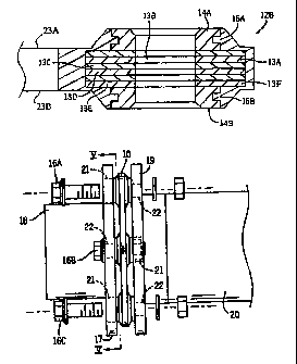
L'invention concerne une pièce d'accouplement flexible (10) qui permet de relier une collerette (17) d'arbre d'entraînement à une collerette (19) d'arbre mené. Des dispositifs d'assemblage à montage circonférentiel (12A-12F) forment dans la pièce d'accouplement des alésages qui sont traversés par des boulons (16A-16F) pour relier cette dernière en alternance à la première puis à la seconde collerette (17, 19). Des dispositifs d'assemblage adjacents (12A-12F) sont reliés ensemble par des liaisons (13A-13E), des rondelles (14A, 14B) étant disposées aux extrémités opposées de l'empilement de liaisons au niveau de chaque dispositif d'assemblage. Selon l'invention, ces rondelles (14A, 14B) sont formées par des gorges périphériques (15A, 15B) dans lesquelles vient se loger la matière plastique qui constitue le corps (11) de la pièce d'accouplement. Ceci permet de bloquer les rondelles (14A, 14B) et d'empêcher leur éjection lorsque les boulons (16A-16F) traversent les alésages.


Abrégé anglais


A flexible coupling (10) is provided to connect a flange (17) on a drive shaft
to a flange (19) on a driven shaft. Circumferentially spaced fastening means
(12A-12F) provide bores through the coupling through which bolts (16A-16F) can
be passed to connect it alternatively to the one and then the other flange
(17, 19). Adjacent fastening means (12A-12F) are interconnected by links (13A-
13E) and washers (14A, 14B) are positioned at opposite ends of the stack of
links at each fastening means. In accordance with the invention the washers
(14A, 14B) are formed with peripheral grooves (15A, 15B) which will be entered
by the plastics material forming the body (11) of the coupling, thus locking
the washers (14A, 14B) against being expelled when bolts (16A-16F) are
subsequently passed through the bores.

Revendications

Note : Les revendications sont présentées dans la langue officielle dans laquelle elles ont été soumises.


7
What is claimed is:
1. A flexible coupling for connecting a drive to a driven shaft, the coupling
comprising:
an annular body of a moldable material;
a number of parallel bores circumferentially distributed about said body, each
bore
opening to opposite sides of the body;
a plurality of link means passing around each bore, each of said link means of
said
plurality of link means having apertures at opposite ends thereof, at least
one of said link means
of said plurality of link means extending from one of said bores to an
adjacent bore in one
direction from said one of said bores, and at least one other of said link
means of said plurality of
link means extending from said one of said bores to an adjacent bore in
another direction from
said one of said bores, at least a portion of each of said bores being formed
exclusively by said
apertures of at least one of said link means; and
washer means on opposite sides of said link means defining end orifices of
each bore,
each washer means having a peripheral formation, said peripheral formation
engaging said
moldable material and locking said washer means against displacement out of
said body.
2. A flexible coupling as claimed in claim 1, in which said coupling couples a
drive
shaft having an annular flange formed with a number of circumferentially
spaced holes to a
driven shaft having an annular flange formed with a number of
circumferentially spaced holes
with a plurality of bolts passing through respective said bores, wherein at
least one of said bolts
fastens the coupling to the flange of the drive shaft and at least one other
of said bolts fastens the
flange on the driven shaft to the coupling.
3. A flexible coupling as claimed in claim 1, wherein said peripheral
formation is a
peripheral groove in each said washer means.
4. A flexible coupling as claimed in claim 1, wherein the moldable material is
a
thermosetting plastics material

8
5. A flexible coupling as claimed in claim 4, wherein the plastics material is
a
urethane polymer.
6. A flexible coupling as claimed in claim 1, wherein the washer means are of
metal.
7. A flexible coupling as claimed in claim 1, wherein the link means are of
composite material.
8. A flexible coupling as claimed in claim 1, wherein the body has parallel
faces
extending between adjacent bores from which the washer means project, the
moldable material
being shaped to surround each washer means projecting from one of said body
faces.

Description

Note : Les descriptions sont présentées dans la langue officielle dans laquelle elles ont été soumises.


CA 02472251 2006-08-08
FLEXIBLE COUPLINC
This invention relates to an improved flexible coupling for eonnecting a drive
to a driven shaft
and to a method of manufacturing the same.
Flexible couplings are known which comprise an annular body, typically of a
plastics material,
incorporating circumferentially spaced, parallel bores through which bolts can
be passed to bolt
the coupling to an annular flange on the drive shaft and to an annular flange
on the driven shat_
The body has an even number of fastening means providuig bores and alternate
bolts connect the
body to the one and then the other flange. Adjaceiit bores are linked so that
as each bolt
connected to the flange on the drive shaft moves it drags with it the bolt
upstream of it connected
to the flange on the driven shaft. The body is substantially inelastic but has
a degree of
flexibility, and this permits minor misalignment between lhe shafts without
destruction of the
coupling. The fastening means providing the bores may bt~ bushes connected by
strands passed
around and between them, but conveniently znay be constituted by, or may
comprise, apertures at
opposite ends of rnetal links. An even number of links is "stacked" with the
apertures at one of
theu respective ends in alignment and the apertures at the other of their
respective ends located
altemately at the adjacent fastening means on opposite sides of the first-
mentioned fastening
means.
Washers are located on opposite sides of each "stack" of 1 inks to provide end
orifices for the
bores.
The problem arises that when a bolt is subsequently pushi:d through a bore of
a previously
manufactured coupling it is liable to push the downstreani washer out of the
body of the
coupling, tlle bond between the washer and the plastics material of the body
being insufficient to
prevent this.
T,Pa-RED ti8323624 v. 2

CA 02472251 2009-09-04
2
The present invention intends to overcome this problem by keying the washers
to the body so
that only a force sufficient to shear the material of the body would be great
enough to allow a
washer to be expelled. In practice forces of this magnitude will not be
encountered.
According a broad aspect of the invention, there is a provided a flexible
coupling for connecting
a drive to a driven shaft, the coupling comprising: an annular body of a
moldable material; a
number of parallel bores circumferentially distributed about the body, each
bore opening to
opposite sides of the body; a plurality of link means passing around each
bore, each of the link
means of the plurality of link means having apertures at opposite ends
thereof, at least one of the
link means of the plurality of link means extending from one of the bores to
an adjacent bore in
one direction from the one of the bores, and at least one other of the link
means of the plurality
of link means extending from the one of the bores to an adjacent bore in
another direction from
the one of the bores, at least a portion of each of the bores being formed
exclusively by the
apertures of at least one of the link means; and washer means on opposite
sides of the link means
defining end orifices of each bore, each washer means having a peripheral
formation, the
peripheral formation engaging the moldable material and locking the washer
means against
displacement out of the body.
In accordance with one aspect of the present invention there is provided a
flexible coupling for
connecting a drive to a driven shaft, the coupling comprising an annular body
of a mouldable
material in which fastener means are incorporated whereby the coupling may be
fastened to the
shafts, the fastener means comprising an even number of parallel bores
circumferentially
distributed about said body, each bore opening to opposite sides of the body,
a plurality of link
means passing around each bore and extending at least one to the adjacent bore
in one direction
from said first-mentioned bore and at least one to the adjacent bore in the
other direction from
said first-mentioned bore, and washer means on opposite sides of said link
means defining end
orifices of each bore, each washer means having a peripheral formation such
that when the body
DOCS #634595 v. 2

CA 02472251 2009-09-04
2a
is moulded to incorporate the fastener means and link means each washer means
will be locked
by the moulded material against displacement out of said body.
In accordance with another aspect of the present invention there is provided
the assembly of a
flexible coupling according to the immediately preceding paragraph, a drive
shaft having an
annular flange formed with a number of circumferentially spaced holes at least
half the number
of the fastener means, a driven shaft having an annular flange formed with a
number of
circumferentially spaced holes at least half the number of the fastener means
and a plurality of
bolts passing through respective said fastener means, half of the bolts
fastening the coupling to
the flange of the drive shaft and the other half of the bolts fastening the
flange on the driven shaft
to the coupling.
Said peripheral formation is preferably a peripheral groove in each said
washer means The
mouldable material is preferably a thermosetting plastics material, such as a
urethane polymer.
DOCS 4634595 v. 2

CA 02472251 2006-08-08
3
The washer means are preferably of metal and the link means imay be of a
composite material
such as thermosetting fibreglass epoxy, each having openi ngs at its opposite
ends which will
constitute part of two adjacent said bores, an even number of links in a
stacked relationship
between a pair of washer means constituting each said bore with altemate links
extending to the
bores on opposite sides of said first-mentioned bore.
The body may have parallel faces from which the washer means project, the
moldable material
being shaped to surround each washer.
In accordance with another aspect of the present invention there is provided a
method of
manufacturing the flexible coupling of the present invention, the method
comprising locating in a
rtxould an annular array of circumferentially spaced fastening means
comprising link means
which extend between adjacent fastening means and washer means on opposite
sides of the link
means, introducing into the mould a therrrrosetting plastics material in a
liquid state so that it
incorporates the fastening means and link means and penetrates said formations
of the washer
means and curing the plastics material.
The mould may be spun while a urethane polymer is introdueed into it in a
liquid state.
A preferred embodiment of the present invention will now be described by way
of non-limitative
example with reference to the accompanying drawings, in which:
Figure 1 is a front elevation of a flexible coupling in accordance with the
present invention;
Figure 2 is an enlarged sectional elevation of one of the f.-ztening means of
the coupling, taken
on the line of Figure 1, and
Figure 3 is a side elevation of the coupling;
Figure 4 is a partly exploded side view of the coupling interposed between
flanges of a drive and
TDO-2ED #3323624 v. 2

CA 02472251 2006-08-08
4
of a driven shaft, and
Figure 5 is a front elevation of one of the flanges taken on the line V-V of
Figure 4.
DETAILED DESCRIPTION OF THE PREFERRED EMBODIMENT
The flexible coupling 10 illustrated comprises an annular body 11 of a
thermosetting plastics
material, such as a urethane polymer, in which are embedcled in an equally
circumferentially
spaced array six similar fastening means The fastening rncans 12A-12F provide
parallel bores
through the body 11 through which bolts l 6A-16F may be passed to secure the
coupling to an
annular flange 17 at one end of a drive shaft 18 and to an annular flange 19
at one end of a driven
shaft 20, alternate bolts securing the coupling first to one iuzd then the
other flange 17,19 when
the coupling is interposed between and substantially coaxially aligned with
the flanges.
Three of the bolts 16A-16C are visible in Figure 4. At the location of the
bolts 16A and 16C the
flange 17 is formed with relatively large- diameter holes biving clearance for
the shanks of the
bolts 16A and 16C but at the location of the bolt 16B it is formed with a
relatively narrower-
diameter hole substantially fitting the shank of the bolt 16B. An example of a
larger hole is
indicated at 21 in Figure 5 and a smaller one at 22.
The larger and smaller holes alternate around the flange 17_ On the
conf~onting flange 19 the
arrangeznent of holes such as 21,22 is the opposite. Thus in the assembled
condition of the
coupling it is substantially incapable Qf angular rnovement relative to the
flange 17 about half of
the bolts 16A-16F but angular movement of the other hal t' of the bolts is
possible within the
lirnits of the larger holes such as 21 in the flange 17. In the case of the
flange 19 the arrangement
is opposite.
TDO-RED #8323624 v. 2

CA 02472251 2006-08-08
The bolts which are immovable relative to the flange 17 cLin move angularly
within the larger
holes such as 21 of the flange 19 and the bolts which can inove angularly
relative to the flange
19 are iminovable relative to the flange 17.
Links 13A-13F have apertures at their opposite ends. These links are of a
composite material
such as thermosetting fibreglass epoxy. They are arra.nged in a stack with the
apertures at one of
their respective ends in alignment to form the central part of the bore of a
fastening means as
illustrated in Figure 2 in the case of the fastening means A first link 13A of
the fastening means
12B extends to the fastening means 12A adjacent to the fastening means 12B
counter-clockwise
as viewed in Figure 1, a second linlc 13B extends to the fa5tening means I2C
adjacent to the
fastening means 12B in the clockwise direction as viewed in Figure 1 and so on
in alternate
sequence. The opposite ends of the links 13A-13F are interleaved with other
similar lizdcs
extending between the fastening means 12A and 12F and between the fastening
means 12C and
12D to form the central parts of the bores of the fastening means 12A and 12C.
By this arrangement, in whichever sense the coupling 10 is rotated by the
drive shaft each
fastening means bolted to the drive shaft flange will drag after it the
adjacent fastening means
bolted to the driven shaft on its upstream side. Meanwhile a minor
misalignaxxent between the
drive and driven shafts can be tolerated by the flexibility of the coupling,
Each fastening means 12A-12F is completed by a pair of washers formed from
metal such as
indicated at 14A, 14B in Figure 2. The washers are located at opposite ends of
the associated
stack of links, such as 13A-13F and protrude from the parallel faces 23A, 23B
of the body 11.
In accordance with the present invention each washer such as 14A and 14B is
forined with a
peripheral groove such as 15A, 15B (Figure 2)_ In the manufaeture of the
flexible coupling the
linlcs and the washers are positioned in a dry mould which is then spur- as a
thermosetang
plastics material such as a urethane polymer is introduced. The plastics
material enters the
TDO-RED #8323624 Y. 2

CA 02472251 2006-08-08
6
grooves such as 15A and and, af-ter the plastics material has hardened, locks
the washers such as
14A, 14B into the body 11 of plastics materf al. This prevents the downstream
washer such as
14A or 14B from being expelled from the body 11 when a bolt is subsequently
passed through
the bore of a fastening means 12A-12F to fasten the coupl I ng either to the
flange of the drive
shaft or to the flange of the driven shaft.
It will be understood that each washer such as 14A, 14B may have a formation
instead of or
additional to the groove such as 15A, 15B which will sezve to lock it within
the moulded body
11.
In the preferred embodiment illustrated the bores of the fastening means 12A-
12F are formed
exclusively by apertures of links such as 13A-13F and a pair of washers, such
as 14A, 14B, all
coaxially aligned. However a bush may extend through the wbole or a part of
the bore, being
surrounded by the links and washers.
Links such as 13A-13F with apertures at their opposite ends are merely
exemplary of the ways in
which adjacent fastening means 12A- 12F may be interconnected. lnstead of or
in addition to the
links strands, for example, resin-impregnated strands may be wound between
bushes constituting
all or part of the bore of each fastening means.
TDO-RED k8323624 v. 2

Dessin représentatif
Une figure unique qui représente un dessin illustrant l'invention.
États administratifs

2024-08-01 : Dans le cadre de la transition vers les Brevets de nouvelle génération (BNG), la base de données sur les brevets canadiens (BDBC) contient désormais un Historique d'événement plus détaillé, qui reproduit le Journal des événements de notre nouvelle solution interne.

Veuillez noter que les événements débutant par « Inactive : » se réfèrent à des événements qui ne sont plus utilisés dans notre nouvelle solution interne.

Pour une meilleure compréhension de l'état de la demande ou brevet qui figure sur cette page, la rubrique Mise en garde , et les descriptions de Brevet , Historique d'événement , Taxes périodiques et Historique des paiements devraient être consultées.

Historique d'événement

Description Date
Inactive : Périmé (brevet - nouvelle loi) 2023-01-03
Lettre envoyée 2021-06-21
Inactive : Transferts multiples 2021-06-03
Représentant commun nommé 2019-10-30
Inactive : TME en retard traitée 2012-01-17
Lettre envoyée 2012-01-03
Accordé par délivrance 2009-11-24
Inactive : Page couverture publiée 2009-11-23
Lettre envoyée 2009-09-18
Exigences de modification après acceptation - jugée conforme 2009-09-18
Inactive : Taxe finale reçue 2009-09-04
Préoctroi 2009-09-04
Inactive : Taxe de modif. après accept. traitée 2009-09-04
Modification après acceptation reçue 2009-09-04
Un avis d'acceptation est envoyé 2009-03-04
Lettre envoyée 2009-03-04
month 2009-03-04
Un avis d'acceptation est envoyé 2009-03-04
Inactive : Approuvée aux fins d'acceptation (AFA) 2009-02-23
Modification reçue - modification volontaire 2008-10-28
Inactive : Dem. de l'examinateur par.30(2) Règles 2008-05-01
Modification reçue - modification volontaire 2008-01-17
Inactive : Dem. de l'examinateur par.30(2) Règles 2007-07-19
Modification reçue - modification volontaire 2007-04-13
Inactive : Dem. de l'examinateur par.30(2) Règles 2006-10-26
Modification reçue - modification volontaire 2006-08-08
Inactive : Correction à la modification 2006-07-25
Modification reçue - modification volontaire 2006-06-23
Lettre envoyée 2006-01-31
Exigences de rétablissement - réputé conforme pour tous les motifs d'abandon 2006-01-18
Inactive : Dem. de l'examinateur par.30(2) Règles 2006-01-03
Réputée abandonnée - omission de répondre à un avis sur les taxes pour le maintien en état 2006-01-03
Lettre envoyée 2005-02-03
Inactive : Correspondance - Formalités 2004-12-15
Inactive : Transfert individuel 2004-12-15
Inactive : Lettre officielle 2004-11-16
Inactive : Transfert individuel 2004-09-22
Inactive : Lettre de courtoisie - Preuve 2004-09-14
Inactive : Page couverture publiée 2004-09-13
Inactive : Acc. récept. de l'entrée phase nat. - RE 2004-09-09
Lettre envoyée 2004-09-09
Demande reçue - PCT 2004-08-02
Exigences pour l'entrée dans la phase nationale - jugée conforme 2004-06-30
Exigences pour une requête d'examen - jugée conforme 2004-06-30
Toutes les exigences pour l'examen - jugée conforme 2004-06-30
Demande publiée (accessible au public) 2003-07-10

Historique d'abandonnement

Date d'abandonnement Raison Date de rétablissement
2006-01-03

Taxes périodiques

Le dernier paiement a été reçu le 2008-12-30

Avis : Si le paiement en totalité n'a pas été reçu au plus tard à la date indiquée, une taxe supplémentaire peut être imposée, soit une des taxes suivantes :

  • taxe de rétablissement ;
  • taxe pour paiement en souffrance ; ou
  • taxe additionnelle pour le renversement d'une péremption réputée.

Les taxes sur les brevets sont ajustées au 1er janvier de chaque année. Les montants ci-dessus sont les montants actuels s'ils sont reçus au plus tard le 31 décembre de l'année en cours.
Veuillez vous référer à la page web des taxes sur les brevets de l'OPIC pour voir tous les montants actuels des taxes.

Titulaires au dossier

Les titulaires actuels et antérieures au dossier sont affichés en ordre alphabétique.

Titulaires actuels au dossier
REXNORD INDUSTRIES, LLC
Titulaires antérieures au dossier
DUANE V. BYERLY
STEWART A. OLSON
Les propriétaires antérieurs qui ne figurent pas dans la liste des « Propriétaires au dossier » apparaîtront dans d'autres documents au dossier.
Documents

Pour visionner les fichiers sélectionnés, entrer le code reCAPTCHA :


Pour visualiser une image, cliquer sur un lien dans la colonne description du document (Temporairement non-disponible). Pour télécharger l'image (les images), cliquer l'une ou plusieurs cases à cocher dans la première colonne et ensuite cliquer sur le bouton "Télécharger sélection en format PDF (archive Zip)" ou le bouton "Télécharger sélection (en un fichier PDF fusionné)".

Liste des documents de brevet publiés et non publiés sur la BDBC .

Si vous avez des difficultés à accéder au contenu, veuillez communiquer avec le Centre de services à la clientèle au 1-866-997-1936, ou envoyer un courriel au Centre de service à la clientèle de l'OPIC.

({010=Tous les documents, 020=Au moment du dépôt, 030=Au moment de la mise à la disponibilité du public, 040=À la délivrance, 050=Examen, 060=Correspondance reçue, 070=Divers, 080=Correspondance envoyée, 090=Paiement})


Description du
Document 
Date
(aaaa-mm-jj) 
Nombre de pages   Taille de l'image (Ko) 
Abrégé 2004-06-29 2 69
Revendications 2004-06-29 2 102
Description 2004-06-29 5 283
Dessins 2004-06-29 2 48
Dessin représentatif 2004-06-29 1 20
Dessins 2006-06-22 2 36
Description 2006-08-07 6 212
Revendications 2006-08-07 2 49
Revendications 2007-04-12 2 56
Revendications 2008-01-16 2 57
Revendications 2008-10-27 2 60
Description 2009-09-03 7 249
Dessin représentatif 2009-10-28 1 11
Accusé de réception de la requête d'examen 2004-09-08 1 185
Avis d'entree dans la phase nationale 2004-09-08 1 225
Courtoisie - Certificat d'enregistrement (document(s) connexe(s)) 2005-02-02 1 105
Courtoisie - Lettre d'abandon (taxe de maintien en état) 2006-01-30 1 174
Avis de retablissement 2006-01-30 1 165
Avis du commissaire - Demande jugée acceptable 2009-03-03 1 162
Avis concernant la taxe de maintien 2012-01-16 1 171
Quittance d'un paiement en retard 2012-01-16 1 164
PCT 2004-06-29 8 506
Correspondance 2004-09-08 1 25
Correspondance 2004-11-15 1 22
Correspondance 2004-12-14 1 37
Taxes 2006-01-17 1 34
Taxes 2006-12-27 1 23
Taxes 2007-12-26 1 25
Taxes 2008-12-29 1 33
Correspondance 2009-09-03 1 38
Taxes 2009-12-28 1 37