Note : Les descriptions sont présentées dans la langue officielle dans laquelle elles ont été soumises.
CA 02472655 2011-01-12
1
IMPLANTABLE BAND WITH NON.MECHANICAL ATTACHMENT
MECHANISM
Randal Byrum
Richard P. Nuchols
[00011
Technical Field
[0002] This present invention relates generally to a surgically implantable
band for encircling a anatomical passageway, and is particularly
directed to an adjustable gastric band for encircling the stomach for the
control of obesity. The invention will be specifically disclosed in
CA 02472655 2004-06-28
2
connection with an improved attachment mechanism for an adjustable
gastric band.
Background Of The Invention
[0003] Since the early 1980s, adjustable gastric bands have provided an
effective alternative to gastric bypass and other irreversible surgical
weight loss treatments for the morbidly obese. The gastric band is
wrapped around an upper portion of the patient's stomach, forming a
stoma that is less than the normal interior diameter of the stomach that
restricts food passing from an upper portion to a lower digestive
portion of the stomach. When the stoma is of the appropriate size,
food held in the upper portion of the stomach provides a feeling of
fullness that discourages overeating.
[0004] In addition to a latched position to set the diameter of the gastric
band,
adjustability of gastric bands is generally achieved with an inwardly
directed inflatable balloon, similar to a blood pressure cuff, into which
fluid, such as saline, is injected through a fluid injection port to achieve
a desired diameter. The balloon is typically deflated or only partially
inflated when first placed in the body to allow for body adjustments
and healing around the new band site. Since adjustable gastric bands
may remain in the patient for long periods of time, the fluid injection
port is typically installed subcutaneously to avoid infection, for
instance in front of the sternum. Following the initial implantation, the
surgeon may adjust the band by loosing or tightening depending on the
patients' needs. Adjusting the amount of fluid in the adjustable gastric
band is achieved by inserting a Huber tip needle through the skin into a
silicone septum of the injection port. Once the needle is removed, the
septum seals against the hole by virtue of compressive load generated
by the septum. A flexible conduit communicates between the injection
port and the adjustable gastric band.
CA 02472655 2004-06-28
3
[0005] An attachment mechanism for the adjustable gastric band has to
provide an initial sizing of the stoma of the stomach. One generally
known attachment is to suture ends of the adjustable gastric band.
Another generally known attachment includes one end of the gastric
band terminating in a flexible conduit that has a flared portion that is
drawn through an opening in a second end of the gastric band and then
sutured to the encircling band portion - securing the band to the
stomach. After the sutures are in place, the injection port is anchored
at a convenient location.
[0006] While these known approaches are effective in securing the gastric
band, further improvements are desired that simplify the clinical
implantation procedure, that provide long-term reliability, and that
facilitate readjustment or removal.
[0007] While sutures have been relied on as the most positive connection in
the past, it is desirable to have a secure attachment that does not
require sutures, yet does not require a large force to create the secure
attachment. Otherwise, it may be difficult to adequately grip and
perform the attachment with laparoscopic instruments. Consequently,
a significant need exists for an adjustable gastric band having an
improvement attachment mechanism.
Summary of The Invention
[0008] The present invention addresses these and other problems in the prior
art, by providing an adjustable gastric band device that is engaged with
less force, thereby facilitating implementation with laparoscopic
instruments, yet the attachment remains secure over long term use.
[0009] A general object of this invention is to provide an adjustable gastric
band having a non-mechanical attachment mechanism.
CA 02472655 2004-06-28
4
[0010] Another object of this invention is to provide a readily reversible
adjustable gastric band which can be fastened and unfastened without
reducing the holding strength of the attachment mechanism.
[0011] Another object of this invention is to provide an adjustable gastric
band having a secure fastening mechanism which can be fastened and
unfastened without minimizing the strength of the attachment
mechanism.
[0012] To achieve the foregoing and other objects, and in accordance with the
purposes of the present invention as described herein, there are described
adjustable gastric bands with non-mechanical attachment mechanisms
connecting the two ends together. The non-mechanical attachment
mechanisms include a hook and loop attachment mechanism, a magnetic
attachment mechanism, an adhesive attachment mechanism and the use
of energy bonding.
[0013] Further novel features and other objects of the present invention will
become apparent from the following detailed description, discussion
and the appended claims, taken in conjunction with the drawings.
Brief Description Of The Figures
[0014] The accompanying drawings, which are incorporated in and constitute
a part of this specification, illustrate embodiments of the invention,
and, together with the general description of the invention given above,
and the detailed description of the embodiments given below, serve to
explain the principles of the present invention.
[0015] FIG. 1 is a diagrammatic drawing showing an adjustable gastric band
wrapped around an upper part of a stomach.
[0016] FIG. 2 is a cross sectional view of the adjustable gastric band of FIG
1
taken along line 2-2.
CA 02472655 2004-06-28
[0017] FIG. 3 is a top, plan view of an adjustable gastric band constructed in
accordance with the present invention having a hook and loop
attachment mechanism.
[0018] FIG. 4 is a top, plan view of an alternate embodiment of the adjustable
gastric band shown in Fig. 3.
[0019] FIG. 5 is a top, plan view of another embodiment of an adjustable
gastric band constructed in accordance with the present invention
having a magnetic attachment mechanism.
[0020] FIG. 6 is a fragmentary, enlarged, perspective view of the two end
portions of an adjustable gastric band constructed in accordance with
the present invention having an adhesive attachment mechanism.
[0021] FIG. 7 is a fragmentary, enlarged, perspective view of the two end
portions of an adjustable gastric band constructed in accordance with
the present invention in which the two ends have been energy bonded
together.
[0022] Reference will now be made in detail to the present preferred
embodiment of the invention, an example of which is illustrated in the
accompanying drawings.
Detailed Description of Embodiments of the Invention
[0023] In the following description, like reference characters designate like
or
corresponding parts throughout the several views. Also, in the
following description, it is to be understood that terms such as front,
back, inside, outside, and the like are words of convenience and are not
to be construed as limiting terms. Terminology used in this patent is
not meant to be limiting insofar as devices described herein, or
portions thereof, may be attached or utilized in other orientations.
Referring in more detail to the drawings, the invention will now be
described.
CA 02472655 2004-06-28
6
[0024] Referring to Fig. 1, an adjustable gastric band 10 is shown wrapped
around an upper portion of a stomach 12, kept in place by attaching the
two ends together and extending a portion 14 of the stomach 12 over
the adjustable gastric band 10 by suturing portion 14 to the stomach.
Referring also to Fig. 2, the adjustable gastric band 10 includes a non-
extensible strap 16 and an inflatable balloon 18, made of a medical
grade silicone polymer or any other suitable material, is carried by the
inner surface 20 of the strap 16. The balloon 18 may be secured to the
inner surface 20 in any well known manner, or even made of unitary
construction with the strap 16, although the strap 16 may typically be
formed of a different material.
[0025] One end of a flexible conduit 22 is in fluid communication with the
internal cavity 24 of the balloon 18, with the other end being in fluid
communication with an internal cavity (not shown) of a remote
injection port 26. The remote injection port 26 includes a silicone
septum 28. At the time the adjustable gastric band 10 is implanted
around a portion of the stomach, the remote injection port 26 is also
implanted at a suitable location, usually within the rectus sheaths, for
transcutaneous access via a Huber needle.
[0026] As is well known, the internal cavity 24, the flexible conduit 22 and
the internal cavity of the remote injection port 26 are preferably at least
partially filled with a physiologically compatible fluid, such as a saline
solution. Postoperative adjustment of the perimeter enclosed by the
balloon 18, and therefore the size of the stoma, is accomplished by
addition or removal of fluid from the interior cavity 24 of the balloon
18 by inserting a Huber needle percutaneously into the silicone septum
28 of the injection port 18.
[0027] As is well known in the field the adjustable gastric band 10 may be
made from any suitable medically compatible material having
CA 02472655 2004-06-28
7
sufficient strength necessary for a particular laparoscopic surgery or
particular patient.
[0028] As mentioned above, the two ends of the adjustable gastric band 10 are
attached together (the specific attachment mechanism structure is not
illustrated in FIG. 1). The present invention is directed to various
embodiments of non-mechanical attachment mechanisms for
connecting the two ends together. The general construction of
adjustable gastric band 10 shown in FIGS. 1 and 2 and described above
is common to the embodiments illustrated in FIGS. 3-7, with the
embodiments differing by the specific attachment mechanisms. It is
noted that the practice of the present invention may be used with any
gastric band, and is not limited to use with an adjustable gastric band
having the exact features described above or below.
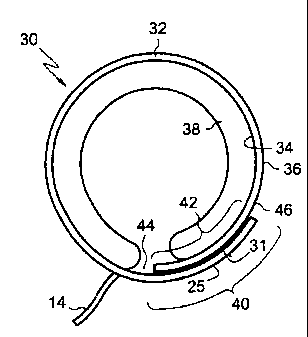
[0029] Turning now to FIG. 3, the adjustable gastric band 30 includes an
elongated strap 32 extending in what is referred to herein as the
longitudinal direction, even though when implanted the adjustable
gastric band 30 has an arcuate configuration. The strap 32 includes an
inner surface 34 and an outer surface 36, with the balloon 38 extending
inwardly from adjacent the inner surface 34. The adjustable gastric
band 30 includes a first end portion 40 which overlaps a second end
portion 42, with the inner surface 34 of the adjustable gastric band 30
at the first end portion 40 being disposed adjacent the outer surface 36
of the adjustable gastric band 30 at the second end 42 portion.
[0030] The first and second end portions 40, 42 are secured together by a non-
mechanical attachment mechanism. For the purposes of this
description, non-mechanical attachment mechanism refers to a
mechanism for latching which is not readily visible with the naked eye.
These include such elements as magnets, adhesives, material welding,
hook-and-loop, and the like. Prior art bands utilize geometry-based
features which create interferences and connections. In the
CA 02472655 2004-06-28
8
embodiment depicted in Fig. 3, the non-mechanical attachment
mechanism is a hook and loop fastener carried by the adjacent surfaces
of the first and second end portions 40, 42. The inner surface 34 of the
end portion 40 carries either the hook material or loop material,
indicated at 44, with the outer surface 36 of the second end portion 42
carrying the corresponding mating material, either the loop or hook
material, indicated at 46. The fastening characteristics of hook and
loop material is well known, with the hook material engaging the loop
material at a very small, micro level, having no specific alignment
between individual hooks and individual loops, with numerous hooks
and loops per square inch of material producing substantial load
sharing with no single hook and loop carrying a substantial portion of
the total load. Even though the operation of hook and loop material
involves hooks partially extending around loops, this attachment
mechanism is considered herein as being non-mechanical.
[0031] The hook and loop material fasteners 44, 46, are attached to the
respective surfaces of the first and second end portions 34, 36 by any
suitable method, such as for example by a physiologically compatible
adhesive. The hook and loop material 44, 46, may be made of any
medically compatible material, including for example stainless steel.
The first and second end portions 40a, 42a overlap a length which is at
least sufficient for the two end portions to be held together for the
particular non-mechanical attachment mechanism used. By way of
example, the overlap length for the hook and loop non-mechanical
attachment mechanism illustrated in FIG. 3 may be approximately 2.5
cm.
[0032] Hook and loop fastener 44, 46 allow easy and quick fastening of the
ends of adjustable gastric band with sufficient holding strength to
remain in place during post operative adjustments to balloon 18, but
which can be removed or adjusted by a surgeon when desired.
CA 02472655 2004-06-28
9
[0033] FIG. 4 illustrates an alternate embodiment of the adjustable gastric
band embodiment of FIG. 3. The adjustable gastric band 30a includes
a hook and loop non-mechanical mechanism carried by the adjacent
surfaces of the first and second end portions 40a and 42a. In this
embodiment the inner surface 34a of the adjustable gastric band 30a at
the second end portion 42a carries the corresponding mating material,
either the loop or hook material 46a to engage the hook or loop
material 44a carried by the inner surface 34a of the adjustable gastric
band 30a at first end portion 40a. In this embodiment, when the first
and second end portions 40a, 42a are secured together, the inner
surface 34a of each are opposed to each other. It is noted that the
connected first and second end portions 40a, 42a, may extend
outwardly at any angle, such as in the general radial direction depicted
in FIG. 4, generally aligned with the center of the area enclosed by the
adjustable gastric band 30a. As alternate to this alternate embodiment,
either the first or second end portion could extend through an opening
formed in the other end portion, or around an edge of the other end
portion, such that the outer surface of the end portions oppose each
other, with hook and loop material being respectively carried by the
opposing surfaces.
[0034] The embodiment shown in FIG. 5 includes a magnetic non-mechanical
attachment mechanism. The adjustable gastric band 48 includes an
elongated strap 50 which has an inner surface 52 and an outer surface
54, with the balloon 56 extending inwardly from adjacent the inner
surface 52. The adjustable gastric band 48 includes a first end portion
58 which overlaps a second end portion 60, with the inner surface 52
of the first end portion 58 being disposed adjacent the outer surface 54
of the second end portion 60.
[0035] Each of the first and second end portions 58, 60 carry a magnetic
material 62, 64, at least one of which is a magnet. As used herein,
CA 02472655 2004-06-28
magnetic material includes a magnet and any material which is
attracted to a magnet. The magnetic material 62, 64 may be any
suitable medically compatible material. When implanted, the first and
second end portions 58, 60, are held together by the magnetic force
between the magnetic material, with the magnetic material being
selected, sized and located so as to produced sufficient magnetic force
therebetween to hold the two end portions 58, 60 together.
[0036] As seen in FIG. 5, the entire first end portion 58 is magnetic material
62, secured to the strap 50 in any suitable manner, such as by heat or
pressure bonding, adhesive, or mechanical attachment such as sewing
or stapling. Alternatively, magnetic material 62 may comprise a shell
disposed around the strap 50.
[0037] The second end portion 60 is illustrated as carrying spaced apart,
discrete members of magnetic material 64, such as strips of magnetic
material extending in a transverse direction across the width of the
second end portion 60 of the strap 50. The members of magnetic
material 64 may extend across the width of the strap 50. The members
of magnetic material 64 may be attached to end portion 60 in any
suitable manner. The members of magnetic material 64 could be
embedded, being enclosed completely by the second end portion 60,
such as being disposed in a cavity formed therein or being molded in
place.
[0038] Any configuration of magnetic material carried by the first and second
end portions 58, 60 may be used. For example, both end portions 58,
60 may be strips of magnetic material. Both may carry one or more
individual magnetic material inserts. The magnetic material on both
end portions 58, 60 may each be one or more magnets (but at least one
of which of any mating pair or portion of magnetic material must be a
magnet), with the appropriate orientation and alignment of the
magnetic poles. The magnetic material may be secured to or in the end
CA 02472655 2004-06-28
11
portions 58, 60 in any suitable manner. The magnetic material may be
flexible or rigid.
[0039] Additionally, the end portions 58 and 60, and magnetic material 62, 64
may be arranged in alternate configurations as discussed above with
respect to the hook and loop attachment mechanism. For example, the
magnetic material on each end portion may be disposed such that the
inner surfaces of the end portions are disposed adjacent each other, or
such that outer surfaces of the end portions are disposed adjacent each
other.
[0040] The embodiment shown in FIG. 6 includes an adhesive non-
mechanical attachment mechanism. FIG. 6 is an enlarged,
fragmentary, perspective view of the first end portion 66 and the
second end portion 68 of the adjustable gastric band 70. At least one
of the inner surface 72 of the adjustable gastric band 70 at the first end
portion 66 and the inner surface 72 of the adjustable gastric band 70 at
second end portion 66 carries an adhesive which is suitable to secure
the two end portions 66, 68 together. As seen it FIG. 6, the inner
surface 72 at first end portion 66 and the inner surface 72 at second end
portion each carry an adhesive 74, 76. The adhesive 74, 76 may be
any adhesive which cures quickly on contact with each, is effective in
bodily fluids, and exhibits sufficient strength, including such as
bonding, impact and tensile strength, and sufficient elongation
characteristics, to secure the two end portions 66, 68 together, yet
allow a surgeon to separate them when desired. Such adhesives
include for example silicone based adhesives. Adhesive 74 may be
different than adhesive 76, but must function together to cure upon
mutual contact. If an adhesive is carried by only one end portion, the
adhesive must cure and bond upon contact with the other end portion.
[0041] Prior to implantation the adhesive may need to be activated. This may
be done chemically, or may be done by removing a protective material
CA 02472655 2004-06-28
12
which covers the adhesive 74, 76 to keep foreign material out and to
prevent accidental contact therebetween.
[0042] The adjustable gastric band 70 is not limited to the configuration
illustrated in FIG. 6. As with the previously described embodiments,
the adjustable gastric band 70 may be configured alternatively be
configured such that the end portions 66, 68 overlap longitudinally, or
such that the outer surfaces 78 of the end portions 66, 68 are disposed
opposing, adjacent each other.
[0043] The embodiment shown in FIG. 7 illustrates an adjustable gastric band
80 having a non-mechanical attachment mechanism achieved by
energy bonding of the first end portion 82 to the second end portion
84. The inner surface 86 of the adjustable gastric band 80 at first end
portion 82 is securely attached to the inner surface 86 of the adjustable
gastric band 80 at the second end portion 84 using a variety of known
energy bonding techniques, including for example silicone energy
bonding. A surgical tool specially designed for energy welding, such
as a grasper (not shown), is used by the surgeon to clamp the two end
portions 82, 84 together, and apply the vibratory bonding energy
required, as known in the art. The present invention contemplates, but
is not limited to any generally known energy bonding like RF welding,
ultrasonic welding, harmonic welding and the like.
[0044] Using the disclosure of the present invention, those skilled in the art
will recognize that other appropriate tools or other bonding processes
may be used in practicing the embodiments disclosed in FIGS. 6 and 7,
such as solvent or heat bonding.
[0045] It will become readily apparent to those skilled in the art that the
above
invention has equal applicability to other types of implantable bands.
For example, bands are used for the treatment of fecal incontinence.
One such band is described in U.S. Patent 6,461,292 which is hereby
CA 02472655 2011-01-12
13
incorporated herein by reference. Bands can also be used to treat
urinary incontinence. One such band is described in U.S. Patent
Application 2003/0105385.
Bands can also be used to treat heartburn and/or acid reflux.
One such band is described in U.S. Patent 6,470,892.
Bands can also be used to treat
impotence. One,such band is described in U.S. Patent Application
2003/0114729.
[0046] Thus, as used herein and in the claims, an implantable band is a band
which may be implanted in a position to occlude flow, such as food or
body fluids, through an anatomical passageway, such as a stomach or
lumen.
[0047] In summary, numerous benefits have been described which result from
employing the concepts of the invention. The foregoing description of
one or more embodiments of the invention has been presented for
purposes of illustration and description. It is not intended to be
exhaustive or to limit the invention to the precise form disclosed.
Obvious modifications or variations are possible in light of the above
teachings. The one or more embodiments were chosen and described
in order to best illustrate the principles of the invention and its practical
application to thereby enable one of ordinary skill in the art to best
utilize the invention in various embodiments and with various
modifications as are suited to the particular use contemplated. It is
intended that the scope of the invention be defined by the claims
appended hereto.