Note : Les descriptions sont présentées dans la langue officielle dans laquelle elles ont été soumises.
CA 02473492 2004-07-14
1
Method for monitoring the pressure in pneumatic tires on vehicles
Specification:
The invention relates to a method for monitoring and wireless signalling a
pressure or a change of pressure in pneumatic tires on vehicles.
A method of that kind, and a corresponding device, are disclosed in DE 198 56
860 A1. The device disclosed by that publication comprises wheel electronics
disposed inside the pneumatic tire and exposed to the pressure prevailing in
that tire. The wheel electronics comprise a battery as a power source, a
pressure sensor for measuring the pressure prevailing in the pneumatic tire,
an
electronic evaluation circuit for evaluating the measured pressure signals
provided by the pressure sensor, and a transmitter controlled by the
evaluation
circuit and transmitting signals, which comprise an information on the
pressure
prevailing in the tire which is derived from the pressure measurement, to a
receiver unit arranged in or on the vehicle. Commonly used pressure sensors
consist of semiconductor-based absolute-pressure sensors, which provide an
electric output signal corresponding to the respective current tire pressure.
The
ts04s055
CA 02473492 2004-07-14
2
receiver unit arranged in or on the vehicle is connected to a display device
intended for signalling to the driver of the vehicle any occurrence of a
dangerous drop in pressure and/or any other information on the condition of
the tire.
Once the wheel electronics have been installed, battery changes are possible
either not at all or only at significant cost. In order to keep energy
consumption
of the wheel electronics low, DE 198 56 86D A1 provides that the tire pressure
information is transmitted by the wheel electronics at time intervals
dependent
on the vehicle speed. At a speed of more than 25 kmlh, tire pressure data are
sent out at time intervals of 54 seconds, for example, white with the vehicle
travelling at lower speed or in stationary condition, they are sent out only
at
intervals of 15 minutes, for example. Adapting the transmission frequency in
this way permits battery service lives of approximately seven years to be
achieved.
In order to further increase the service life of the battery, DE 199 39 936 A1
teaches to provide the wheel electronics with a receiver capable of receiving
an
interrogation signal from an interrogation transmitter provided in or on the
vehicle. Every time an interrogation signal is received the unit provided for
this
purpose is then caused to transmit tire pressure data. Thus, the
energy-intensive transmission of tire pressure data will be initiated only
when
data regarding the tire pressure are actually needed. This especially permits
to
do without any transmission of pressure data white the vehicle is parked. It
is,
however, a disadvantage of that solution that in the case of a defect of the
interrogation transmitter no tire pressure monitoring will occur.
Now, it is the object of the present invention to open up a way how to achieve
reliable tire pressure monitoring in a low-cost way, while preserving long
service lives for the batteries.
ts04s055
CA 02473492 2004-07-14
3
This object is achieved by a method having the features defined in Claim 1.
Advantageous further developments of the invention are the subject matter of
the sub-claims.
The method according to the invention makes use of the advantages of a tire
pressure monitoring system having an interrogation transmitter as disclosed in
DE 199 39 936 A1 without, however, accepting the disadvantages of that
publication. As long as the interrogation transmitter is intact, the
interrogation
signals will cause the wheel electronics to send out information on the
pressure
or a change of pressure in the tire. However, once no interrogation signals
are
received - for whatever reason - the wheel electronics will at the end of a
predetermined period of time adopt a second mode of operation in which
transmission will be effected at an internally established transmission rate.
That
transmission rate either may be firmly preset, or may be variable and be
internally established using physical values measured by the wheel
electronics,
for example as a function of the pressure or of the speed at which pressure
changes take place, or as a function of the vehicle speed (speed of the wheel.
It is an especial advantage of the invention that the method according to
the invention, while making use of the advantages of the interrogation
transmitter with a view to achieving especially energy-saving operation,
does not depend on such an interrogation transmitter for achieving
reliable monitoring of the tire pressure. Thus, uninterrupted monitoring of
the tire pressure is possible with advantage even in the event of a defect of
the
interrogation transmitter. Especially, a wheel electronics unit using the
method
according to the invention can be used on both vehicles with an interrogation
transmitter and vehicles without an interrogation transmitter, without any
changes or adjustments being required. While heretofore different wheel
electronics systems were required for vehicles with an interrogation
transmitter
according to DE 199 39 936 A1 and vehicles without an interrogation
transmitter, it is now sufficient to produce a single configuration of wheel
ts04s055
CA 02473492 2004-07-14
4
electronics for both applications. Accordingly, there is no need in future to
convert the production process for adapting it to different types of wheel
electronics. Instead, production can be concentrated on a single configuration
of wheel electronics, and the production numbers can be increased. This in
turn leads to lower production costs and facilitates the logistics and
store-keeping functions. In addition, it is an advantage that workshops,
instead
of being required to keep on store different types of wheel electronics, can
concentrate on a single configuration that fits all types of vehicles, whether
with
or without an interrogation transmitter, and that can be installed blind, so
to
say.
Preferably, the pressure or change of pressure is measured according to an
internal program in a first mode of operation. Although it will of course be
sufficient to carry out a single pressure or pressure-change measurement in
response to an interrogation signal, repeated measurements provide the
advantage of allowing a more reliable information on the pressure or the
change of pressure to be obtained, for example for the purpose of deriving the
average of several values measured. Preferably, the measurements performed
in the first mode of operation are carried out independently of the
interrogation
signal, for example always at a fixed interval of 1 s, for example. This
feature
provides the advantage that the wheel electronics are always provided with
current information on the pressure or pressure changes, and are in a position
to send out such information directly after receipt of an interrogation
signal.
Preferably, the same measuring rates are employed for the first and the second
modes of operation. The energy consumption connected with the pressure or
pressure-change measurement is substantially lower than the energy
consumption connected with the transmitting operation. However, different
measuring rates for the first and the second modes of operation are of course
also possible.
ts04s055
CA 02473492 2004-07-14
An advantageous further development of the invention provides that the first
control signal is derived from the action of unlocking the vehicle. With the
vehicle in the parked condition, there is no need for permanently monitoring
the
tire pressure. It is then sufficient if information on the condition of the
tire is
signalled at the beginning of the next travel. If the wheel electronics are
then
set to the first mode of operation by a first control signal derived from the
action
of unlocking the vehicle, first information on the condition of the tire can
already
be obtained, by interrogation of the wheel electronics, during the period of
time
usually elapsing between the actions of unlocking and of starting the vehicle.
Preferably, a signal of a radio key or a signal derived therefrom is used as a
first control signal.
An advantageous further development of the invention provides that an electric
signal, causally derived from rotation of the wheel, is derived in the wheel
electronics and is used for controlling the transmission rate in the second
mode
of operation. A pressure drop in a vehicle tire is much more dangerous at high
vehicle speed than at low vehicle speed. When a vehicle is parked or is moving
at slow speed, the transmission intervals may therefor be significantly longer
than when the vehicle is moving at fast speed, so that transmission energy can
be saved in this manner. Preferably, transmission is effected at time
intervals
TO of 54 seconds, for example, when a minimum speed is exceeded, or at
longer time intervals of 15 minutes, for example, when a minimum speed is
reached or in the stationary condition of the vehicle. Although, preferably,
the
two minimum speeds are equal, they may also deviate one from the other by
hysteresis. Preferably, the signals derived from rotation of the wheel are
used
for varying the time interval T0. It is possible in this way, for example, to
increase the transmission rate as speed rises. Signals derived from rotation
of
the wheel can be obtained for this purpose for example by means of a
centrifugal sensor provided as part of the wheel electronics, whose signal is
modulated by gravity in proportion to the speed of the wheel, as disclosed in
WO 01169265 A1. A switch responsive to rotation of the wheel, which simply
ts04s055
CA 02473492 2004-07-14
6
detects the condition that a minimum speed has been reached and then causes
transmission to be effected at time intervals reduced from T1 to TO is
connected with less apparatus input.
Another advantageous further development of the invention provides that the
pressure or pressure change signals are evaluated in the wheel electronics
and that the transmission rate is adjusted in the second mode of operation in
response to the speed of the pressure changes. When the wheel electronics
determine that a rapid pressure change is taking place, where a predetermined
threshold value of the pressure change of, for example, 0.2 bar/min is
exceeded within a predetermined period of time, then the transmission rate
will
be increased. This feature provides the advantage that the transmission rate
can be comparatively lower in the case of a slow, creeping pressure drop or
when pressure remains constant, without a risk that this may lead to a loss of
safety, because a dangerous rapid pressure drop can nevertheless be
signalled to the driver of the vehicle immediately. Preferably, in a first
mode of
operation the wheel electronics will signal a pressure change when a
predetermined threshold speed value is exceeded, without waiting for an
interrogation signal. Such transmission need not necessarily occur immediately
after the first measured value indicating that the pressure is dropping
rapidly
has been received. Rather, in order to improve reliability, it is advantageous
for
this purpose to first derive an average of several measured values, for which
purpose the measuring rate is increased, for example from 1 measurement per
3 seconds to 1 measurement per 0.8 seconds. It is thus possible with
advantage to immediately signal to the driver of the vehicle any dangerous
rapid pressure drop, and this both in the first and in the second modes of
operation. Although, it would be generally sufficient in this case for the
wheel
electronics to transmit a signal once a rapid pressure drop has been
determined, without waiting for an interrogation signal, it is, however,
preferred
that in the case of a rapid pressure drop the wheel electronics will transmit
ts04s055
CA 02473492 2004-07-14
7
signals at a rapid transmission rate in both the first and the second modes of
operation.
According to another advantageous further development of the invention it is
provided that the wheel electronics can be set, by a third radio control
signal
received from outside of the wheel electronics, to a third mode of operation,
in
which it does not transmit any signals whatever until it leaves that third
mode of
operation again in response either to a first control signal or to the fact
that a
minimum vehicle speed has been reached, and adopts the first or the second
mode of operation. Preferably, pressure or pressure changes are likewise no
longer measured in that third mode of operation. The third mode of operation
is, therefore, characterised by extremely low energy consumption. Thus, it is
especially well suited for storage of the wheel electronics, for example in
workshops. fn order to permit the wheel electronics to be stored in an
especially energy-saving way, they can be set to the especially energy-saving
third mode by means of a hand-held device capable of transmitting the third
control signal. However, the third mode of operation is also suited for parked
vehicles. The third control signal can be derived with advantage from the
action
of locking the vehicle, for example. Based on the first control signal, which
preferably can be derived from the action of unlocking the vehicle, or - if no
first
control signal is received - once the minimum speed, which may be determined
for example by means of a roll switch as described above has been reached,
the wheel electronics of a parked vehicle will then leave that third mode of
operation and adopt the first or second mode of operation. Whether the wheel
electronics change from the third mode of operation to the first or to the
second
mode of operation when the minimum speed is exceeded is in fact not really
important as the wheel electronics will anyway change over from the first mode
of operation to the second mode of operation if no interrogation signal is
received.
cso~soss
CA 02473492 2004-07-14
g
Further details and advantages of the invention will be described hereafter by
way of one embodiment of the invention, with reference to the attached
drawings.
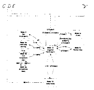
Figs. 1 to 3 show sections of a flow diagram of the method according to the
invention.
Fig. 1 shows a section illustrating a storage mode and the third mode of
operation;
Fig. 2 shows a section illustrating the second mode of operation; and
Fig. 3 shows a section illustrating the first mode of operation.
The sections of the flow diagram shown in Figs. 1, 2 and 3 should be
assembled so that the lines identified by the same capital letters A, B, C, D,
E
and F, respectively, abut each other.
Before the wheel electronics are started up for the first time, they rest in a
storage mode which is identified as mode Oa in Fig. 1. In that storage mode,
no
transmission is effected, only pressure is measured at periodically recurring
time intervals. When pressure is determined to rise above a predetermined
threshold value, for example 1.5 bar, in that storage mode, the wheel
electronics are activated and are transferred to the second mode of operation
comprising the sub-modes 1 a, 1 b and 2 as shown in Fig. 2. In that second
mode of operation, pressure is measured at time intervals t0 of, for example,
three seconds, and a signal containing information on the pressure or a change
of pressure is sent out at time intervals T0. The transmission rate TO depends
on the driving speed of the vehicle. Once a predetermined minimum speed of,
for example, 25 km/h is exceeded, the time intervals between transmission of
the pressure data of, for example, 15 minutes in sub-mode 1 a is reduced to 54
ts04s055
CA 02473492 2004-07-14
9
seconds in sub-mode 1 b. Preferably, a switch responsive to the rolling motion
serves to determine if the predetermined minimum speed has been exceeded.
The fact that the minimum speed has been exceeded results in the switch
being closed, which is indicated by RS = 1 in Fig. 2, and thus in a faster
transmission rate. When the vehicle is moving slowly, or in the stationary
condition of the vehicle, the switch is open which is indicated by RS = 0 in
Fig.
2 and which leads to a slower transmission rate.
When the wheel electronics receive the first control signal they adopt a first
mode of operation in which information on the pressure or a pressure change is
transmitted in response to an interrogation signal. The first mode of
operation
is illustrated as mode 1 c in Fig. 3, and the first control signal may be the
signal
indicated by LF code 5 or the signal indicated by LF code 0. If no such
signals
are received, the wheel electronics, at the end of a predetermined period of
time tt of, for example, 1 to 2 minutes, will return to the second mode of
operation the respective sub-mode of which is indicated as mode 1 d in Fig. 3.
This guarantees that reliable tire-pressure monitoring is ensured even if the
interrogation transmitter should be damaged. Preferably, the first control
signal
by which the wheel electronics are transferred to the first mode of operation
is
triggered by the action of unlocking the vehicle door. The first
pressure-measuring data may be obtained already in the period of time
between unlocking of the vehicle door and starting of the driving motion to
that
a warning regarding an excessively low tire pressure will be available before
the vehicle starts running.
In case a rapid pressure drop is determined by the wheel electronics
transmission is effected internally at shorter time intervals and, preferably,
the
measuring rate is increased in both the first and the second modes of
operation. If a rapid pressure drop is detected, this will lead to an
increased
transmission rate not only in the second mode of operation, but also in the
first
ts04s055
CA 02473492 2004-07-14
1
mode of operation. The corresponding sub-mode is illustrated as mode 2 in
Figs. 1 and 3.
In order to permit energy consumption to be further reduced, the wheel
electronics may be transferred, by a third external control signal indicated
as
LF code 7 in the Figures, to a third mode of operation indicated as mode 1 a
in
Figs. 1 to 3. In that third mode of operation, pressure measurements are no
longer carried out, and signals are not transmitted either. An external
control
signal, indicated as LF code 0 in the Figures, can then return the wheel
electronics from that third mode of operation, which is especially favourable
for
longer times of storage, to the mode of operation it has been in before, i.e.
to
the storage mode, the first or the second mode of operation. When the wheel
electronics had been set to the energy-saving third mode from the first or
second mode, it is preferably set back to that second mode when the switch
responds to rolling of the wheel so that reliable monitoring of the tire
pressure
is in any case ensured.
In addition to the tire pressure, the wheel electronics preferably also
permanently detect the temperature in the tire and incorporate the fatter in
their
evaluation of the measured signals. Given the fact that tire pressure
naturally
increases as temperature rises, it is possible in this way to prevent any
unnecessary warning regarding excessively high or low tire pressure values
and to improve the quality of the tire-pressure monitoring function. Trouble-
free
operation of the wheel electronics, which usually comprise an ASIC or a
microprocessor, is no longer guaranteed above a given material-dependent
threshold temperature. It is for that reason that, conveniently, the wheel
electronics get inoperative in both the first and the second modes of
operation
when a predetermined threshold temperature of, for example, 120°
Celsius is
exceeded. The respective modes are indicated as modes 3a, 3b and 3c in Figs.
2 and 3. When the temperature drops below another threshold temperature of,
for example, 100° Celsius the wheel electronics are rendered active
again, for
ts04s055
CA 02473492 2004-07-14
ll
example by a PTC thermistor provided as part of the wheel electronics. In
order
to avoid unnecessarily frequent switching operations, caused by minor
temperature variations, it is convenient to set the second threshold
temperature
at a somewhat lower level compared with the first threshold temperature.
A forth control signal, indicated as LF code 3 in Figs. 1 to 3, can set the
wheel
electronics to a test mode Ic. In that condition, repair and maintenance work
as
well as function tests to be performed as a quality control measure before
installation of the system can be carried out.
A considerable advantage of such wheel electronics operating according to the
method described with reference to Figs. 1 to 3 now resides in the fact that
although it is absolutely possible to make use of the advantages of an
interrogation transmitter with a view to achieving an especially comfortable
and
energy-saving tire-pressure monitoring system, reliable tire-pressure
monitoring is possible also in a vehicle without any such interrogation
transmitter. It is sufficient, for both vehicles with or without an
interrogation
transmitter, to produce and keep on store only one configuration of a wheel
electronics unit.
As has been described before, the wheel electronics are initially in their
storage mode (mode Oa), before they are put in operation for the first time.
Starting out from that storage mode, the wheel electronics are activated once
pressure is detected to rise above a predetermined threshold value, indicated
as a pressure of 1.5 bar in Fig. 1. In the storage mode, the wheel electronics
therefore measure the pressure at periodically recurring time intervals.
Although no signals whatever are transmitted in the storage mode, even the
energy consumption connected with the periodic pressure measurements
constitutes a drain on the battery of the wheel electronics - especially in
the
case of extended storage periods. in order to nevertheless be able to store
the
wheel electronics over extended periods of time, without reducing the service
ts04s055
CA 02473492 2004-07-14
IZ
life of the battery in subsequent operation, it is provided that the wheel
electronics can be set, via an external signal indicated as LF code 7 in Fig.
1,
from its storage mode to a third mode of operation (mode 1 e) in which there
is
no transmission and no measuring operation, either. The external control
signal, by which the wheel electronics can be set to that energy-saving third
mode of operation can be transmitted for example by means of a hand-held
device.
Now, when a wheel electronics unit in its third mode of operation is supplied
with pressure values prevailing inside a tire, it is not activated by that
fact alone
because no pressure measurements are effected in that operating mode. In
order to be activated, the wheel electronics must first be set back to their
storage mode in which pressure measurements are carried out. This may be
effected, for example, by means of a hand-held device by transmission of a
corresponding control signal, indicated as LF code 7 in Fig. 1. When the wheel
electronics leave the described third mode of operation, they always return to
their last mode they were in immediately before they were transferred to the
third mode. If, for example, the wheel electronics had been transferred to the
third mode of operation from the storage mode, they can be set back from the
third mode of operation to no other mode than the storage condition.
Normally, the wheel electronics should be activated before being installed in
a
tire on a vehicle. However, it may of course happen that a wheel electronics
unit, which had been transferred from the storage mode to the third mode of
operation, is installed on a vehicle in that condition. In order to permit
tire
pressure to be monitored in this case as well, the wheel electronics comprise
a
roll switch for setting back the wheel electronics from the third mode of
operation to their previous mode of operation, for example the storage mode,
once a predetermined minimum speed is exceeded. When a pressure above
the predetermined threshold value is then detected by the wheel electronics in
their storage mode, they adopt the sub-mode 1 a of the second mode of
ts04s055
CA 02473492 2004-07-14
13
operation. However, instead of changing over directly from the storage mode to
the second mode of operation, the wheel electronics pass through an
intermediate mode defined as mode Ob. In that intermediate mode function
tests can be carried out. In addition, intermediate mode 0b serves to prevent
activation of the wheel electronics on the basis of a single defective
measuring
result. It is for this purpose that pressure is measured repeatedly in
intermediate mode Ob. 4nly when such measurements reveal that the
predetermined threshold pressure value is exceeded for a predetermined
period of time will the wheel electronics change over from intermediate mode
Ob to sub-mode 1 a of the second mode of operation; otherwise they will return
to their storage mode.
Thus, while a vehicle without an interrogation transmitter needs to have a
roll
switch in the wheel electronics in order to permit the tire to be monitored in
any
case, this is not so for a vehicle equipped with an interrogation transmitter.
For, the interrogation transmitter is caused to send out a first control
signal by
the action of unlocking the vehicle door. In this context the term first
control
signal is meant to describe any control signal that sets the wheel electronics
to
their first mode of operation, either directly or indirectly. fn the
embodiment
illustrated in Figs. 1 to 3, a first control signal may therefore consist of
the
control signals indicated as LF code 0 and LF code 5, or may include one or
both of such control signals. In the case of the described embodiment, the
first
control signal triggered by unlocking of the vehicle door contains the signals
indicated as LF code 0 and LF code 5. When the wheel electronics were in
their third mode of operation at the time a vehicle door was unlocked, they
are
therefore transferred by the first control signal to their previous mode, i.e.
in the
described case to their storage mode. Now, when the tire pressure is found to
exceed the predetermined threshold value, the wheel electronics are then set,
by that part of the control signal which is identified as LF code 5, to the
first
ts04 s05 5
CA 02473492 2004-07-14
14
sub-mode 1 c of the first mode of operation, via intermediate mode Ob and
sub-mode 1 a of the second mode of operation.
Preferably, unlocking of a vehicle door triggers not only a single
transmission
of a first control signal, but rather repeated transmission thereof. This
generally
improves the reliability of the system. It is especially preferred in this
connection if the first control signal also includes a string indicated as LF
code
8 in Fig. 1. When such a string is received by the wheel electronics, in their
storage mode, they adopt sub-mode 1 a of the second mode of operation,
irrespective of the pressure value measured. That part of the first control
signal, which is indicated as LF code 5 in Fig. 3, causes the wheel
electronics
to then adopt their first mode of operation and to transmit data regarding the
tire pressure, or a change of tire pressure, in response to an interrogation
signal.
The advantage of an interrogation transmitter is seen, among other things, in
the fact that the measured pressure data can be inquired already during the
time between the moment a vehicle door is unlocked and the moment the
vehicle starts moving, and that a warning regarding an excessively low tire
pressure can be emitted, if necessary, already when the vehicle is being
started.
During the running period of the vehicle that follows, the wheel electronics
mounted in the tires of the vehicle are then caused at regular intervals, by
corresponding interrogation signals, to transmit information on the pressure
or
on pressure changes in the tire. Preferably, the interrogation signals are
sent
out at shorter time intervals when the vehicle is moving at fast speed than
when
it moves at slow speed. In this way, current information on the pressure, or a
change of pressure, is made available at shorter time intervals when the
vehicle moves at fast speed. At fast speed, any pressure drop in a tire would
be
much more dangerous than at slower speed. Accordingly, the interrogation
ts04s055
CA 02473492 2004-07-14
intervals, and correspondingly the transmission intervals, may be considerably
longer at slow speed than at fast speed so that transmission energy can be
saved in this way.
If the wheel electronics determine by two successive measurements that the
tire pressure has dropped by mare than a predetermined value, i.e. that a
rapid
pressure drop has occurred, the internal measuring rate will be increased. For
example, the pressure then will be no longer measured at intervals of three
seconds, but already at intervals of 0.3 seconds. If this confirms the rapid
pressure drop the wheel electronics wilt transmit a signal regarding the
pressure or the pressure variation in their first mode of operation without
waiting for the receipt of an interrogation signal. A rapid pressure drop in
movement of the vehicle is extremely dangerous and should, therefore, be
signalled to the driver of the vehicle at the earliest possible time.
When a vehicle equipped with an interrogation transmitter is parked,
interrogation signals are no longer sent out. When interrogation signals are
no
longer received by the wheel electronics they will switch over to sub-mode 1 d
of the second mode of operation at the end of a predetermined period of time
tt,
for example at the end of one to two minutes. Normally, measuring and sending
are not necessary in a parked vehicle equipped with an interrogation
transmitter since the interrogation transmitter will be reactivated before the
vehicle starts moving again, for example for transmitting the first control
signal
triggered by unlocking of a vehicle door. When interrogation signals are no
longer received, the wheel electronics could therefore normally change over
from mode 1 c of the first mode of operation to the third mode of operation in
which no measuring and no transmission occurs any more. However, in order
to achieve the best possible reliability of the tire pressure monitoring
function,
the wheel electronics will continue their measurements at time intervals t0
and
continue to send information regarding the pressure or any pressure variation
ts04s055
CA 02473492 2004-07-14
16
at time intervals TO also with the vehicle in parked condition, i.e. in sub-
mode
1 d of the second mode of operation.
In the case of a vehicle without an interrogation transmitter, the wheel
electronics will be transferred, as described above, from their storage mode
to
sub-mode 1 a of the second mode of operation. This mode of operation largely
resembles sub-mode 1 d of the second mode of operation since in sub-mode 1 a
of the second mode of operation the tire pressure is likewise measured at time
intervals t0, and a corresponding signal containing information on the
pressure
or any pressure variation is transmitted at time intervals T0. Sub-mode 1 a of
the second mode of operation is assumed by the wheel electronics of a vehicle
without an interrogation transmitter in the parked condition of the vehicle
and
when the vehicle is driving at slow speed. When a predetermined minimum
speed of, for example, 25 km/h is exceeded, the wheel electronics are set, by
response of the roll switch, to sub-mode 1 b of the second mode of operation.
In
sub-mode 1 b of the second mode of operation, the time intervals for the
transmission of pressure data of, for example, 15 minutes in sub-mode 1 a are
reduced to 54 seconds. It is thus possible with advantage to adopt the
transmission rate to the driving speed even when an interrogation transmitter
is
not present or not operative, so that transmission energy can be saved. When
the wheel electronics detect a rapid pressure drop in the second mode of
operation, then the measuring rate and the transmission rate are increased.
When a tire equipped with wheel electronics has been changed from a vehicle
equipped with an interrogation transmitter to a vehicle without such an
interrogation transmitter, then the wheel electronics will first adopt sub-
mode 1 d
of the second mode of operation. However, once the vehicle starts running and
the roll switch detects that the predetermined minimum speed is exceeded, the
wheel electronics will then change over to sub-mode 1 a of the second mode of
operation and from there, if necessary, to sub-mode 1 b of the second mode of
operation. In this way, uninterrupted monitoring of the tire pressure can be
ts04s055
CA 02473492 2004-07-14
17
guaranteed even when a tire is changed or in the event of a sudden defect of
the interrogation transmitter.
ts04s05 5