Note : Les descriptions sont présentées dans la langue officielle dans laquelle elles ont été soumises.
CA 02473692 2004-07-16
WO 03/061930 PCT/CA03/00051
- 1 -
MOLDING METHOD AND SUPPORT SYSTEM FOR
THERMOFORMABLE MATERIAL SHEET
TECHNICAL FIELD
The present invention relates to a method and
apparatus for molding thermoformable material sheet,
particularly for forming high strength fibre reinforced
composite parts, such as composites containing continuous
reinforcing filaments. More particularly, the invention
relates to a method and apparatus for supporting and
tensioning a thermoformable material sheet and to handle
this sheet during various phases of a molding process.
BACKGROUND ART
Thermoforming/stamping for continuous reinforced
thermoplastic composite materials is a process wherein a
stack of composite sheets, preheated to the melting
temperature of the resin, are installed between two rigid
mold sections. The sections define the surface contour of
the part being formed and are stamped to the desired shape
by closing the mold.
Two main techniques for high volume production of
continuous fibre reinforced thermoplastic parts
(hereinafter referred to as "CFRTP") are currently used in
the industry. These are the matched-die forming and the
rubber-forming techniques. In the matched-die technique,
the two mold sections are machined to a desired shape from
steel or aluminium. The size of each mold section is such
that, once the mold is closed, the gap between the mold
section establishes the thickness limit of the finished
part thickness to ensure quality. This molding technique
CA 02473692 2004-07-16
WO 03/061930 PCT/CA03/00051
- 2 -
allows high volume production of parts and ensures a good
surface finish.
One drawback of this technique is the risk of
premature solidification and fracture of the laminate
during mold closure due to the high thermal conductivity of
metallic molds.
A second significant drawback is that friction is
induced between the laminate and the mold cavity during
mold closure, especially for molds having small draft
. angles along lateral walls. This friction is mainly
explained by the increase of the laminate thickness caused
by the reorientation of the fibres along lateral walls of
the mold. If improper machining of the mold sections
creates cavity thickness distribution in the mold
inconsistent with the part, after reorientation of the
fibres and redistribution of the material, high-friction
zones or, conversely, unpressurized 'zones are created over
the laminate. The laminate friction along lateral walls of
the mold significantly increases the tensile in-plane
stress and shear deformations in the laminate and increases
the risk of fibre breakage, laminate premature
solidification (due to intimate thermal contact with the
mold over a large surface) and resin percolation. A
variation between the thickness of the laminate and that of
the cavity, with a laminate locally much thicker than the
cavity, can prevent mold closure or locking with subsequent
damage.
In addition to the limitations noted previously,
another drawback of the matched-die technique is the
presence of variable consolidation pressures over the part
area during mold closure. This is pronounced over the
sides of deep parts having low draft angles for which the
CA 02473692 2004-07-16
WO 03/061930 PCT/CA03/00051
- 3 -
consolidation pressure is a small fraction of the total
mold closing load. The matched-die forming technique
necessitates machining of a male section such that the mold
cavity has a variable thickness that matches closely the
final thickness distribution of the part after molding.
Such thickness must be precisely predicted prior to mold
fabrication, using modelling computer programs, to avoid
unconsolidated or poorly consolidated regions over the part
area. These procedures increase the design labour and time
and the manufacturing costs.
In respect of the rubber-forming technique this is
similar to the matched-die technique. In this methodology,
the male section of the mold is made of, for example,
rubber and molded to the desired part geometry. The
advantages of using a rubber punch are that during mold
closure the rubber deformation allows the application of a
quasi-hydrostatic pressure over the part area. This
ensures improved conformation of the laminate to the mold
geometry compared to the matched-die process and permits
more flexibility in the punch design. Further, lower
thermal conductivity of the rubber punch reduces the
cooling rate of the laminate, allowing more time to mold
the part before premature solidification arises. However,
compared to the matched-die technique, some drawbacks are
encountered, such as:
~ A molded part having a good surface finish on one side
only (the rubber punch being easily indented by the
fibres of the laminate, inducing a rough surface
finish);
~ An increased risk to induce friction between the
laminate and the mold cavity during mold closure owing
to the increased size of the rubber punch under
CA 02473692 2004-07-16
WO 03/061930 PCT/CA03/00051
- 4 -
deformation. Indeed, the membrane stress applied on
the laminate by the supporting system is transferred
to the punch which, in the case of a soft rubber
punch, will deforms and expands laterally. In such a
case, premature laminate solidification and part
defects can be induced during mold closure due to the
increase of the laminate friction over the side walls
of the mold cavity, similar to the case explained
above in relation with the matched-die forming process
and the prior art;
~ The locking of the mold closure (known as
"barrelling") induced by an excessive lateral
expansion of the punch is such that it becomes
impossible to completely close the mold;
~ The punch can collapse (or locally buckle) under
compression loads induced during mold closure for part
geometries having large depth to width (or length)
ratios. Such behaviour can be observed for the whole
punch or over local regions of the part for which the
depth to width ratio promote local buckling of the
punch;
~ An increased risk to obtain part distortions after
molding due to the unbalance of part cooling on the
punch side as compared to the cavity side (rubber
having a much lower thermal conductivity than metals);
~ The machining of two mold cavities is necessary, one
corresponding to the mold cavity and the other one
used to mold the rubber punch. This increase the
fabrication time and the overall manufacturing costs;
~ The rubber behaviour under deformation has to be well
known in order to insure a good part quality. Indeed,
CA 02473692 2004-07-16
WO 03/061930 PCT/CA03/00051
- 5 -
a good conformation of the laminate in the corners and
the reduced risk to induce the ~~barrelling" and mold
locking effects are usually achieved with hard rubbers
while a quasi-hydrostatic pressure applied over the
part area for consolidation is insured when soft
rubber are used.
~ Moreover, the high thermal expansion property of
elastomer is such that the thermal expansion of the
punch under the effect of heat can easily overpass the
volume of the mold cavity, especially for large molds.
This must be accounted for in the mold design,
increasing the design difficulties and delay.
Many other techniques have been developed to mold
CFRTP parts using rubber membranes assisted by a vacuum
and/or air pressure to conform the laminate to the mold
geometry. Some examples of these techniques include
thermoforming, as illustrated in patent publication number
FR-2696677-A1, double-diaphragm thermoforming technique, as
illustrated in patent publication number EP-0410599-A2, and
a thermoforming technique using four diaphragms, as
illustrated in Australian patent number 738958, wherein one
pair on each side of the part with hot oil flowing inside
each pair of diaphragm to reduce the cooling rate of the
laminate. The main drawback of these techniques is their
low volume capability of parts molding, due to the high
labour needed to prepare to mold prior to molding and to
the low cycle life of rubber membranes submitted to large
deformations, wear friction and large temperatures.
Finally, a general stamping technique for shaping synthetic
materials, using a male and female mold sections made of
rigid backing members mounted by facing units and defining
the contours of the mold cavity. Again, similar to the
CA 02473692 2004-07-16
WO 03/061930 PCT/CA03/00051
- 6 -
matched-die and the rubber-forming processes described
above, the risks of laminate friction along lateral walls
of the mold are present, especially for parts having small
draft angles.
No documented techniques have been developed to
support, apply tension loads and follow the movements of
the laminate in the thermoforming/stamping process for
CFRTP parts. For small parts, a blank holder similar to
what is used in the stamping process of steel sheet, can be
used to induce membrane stresses in the laminate during
mold closure. However, the system does not provide
adequate control of membrane tension and renders impossible
the application of different loads at different locations
about the periphery of the laminate. Moreover, if the
holder is made of a flat steel ring compressing the
laminate over the flat region of the mold cavity, it can
create premature cooling of the thermoplastic matrix due to
heat removed by conduction. This has an affect on the
quality of the molded part.
INDUSTRIAL APPLICABILITY
The present invention has applicability in the
manufacturing art.
DISCLOSURE OF T8E INVENTION
The present invention addresses the foregoing problems
of the prior art and is mainly directed to providing an
improved method and apparatus for molding parts made of
thermoformable sheet material, such as CFRTP composite
materials.
According to a first object of an embodiment of the
invention, this is provided a method of molding a
CA 02473692 2004-07-16
WO 03/061930 PCT/CA03/00051
thermoformable sheet material having opposed sides,
characterized in that the method comprises the steps of:
providing a mold having a first section and a
second section, the first section including a
compliant mold member, the second section including a
rigid mold base configured to releasably receive the
first section;
providing a selectively pressurizable diaphragm
in the first section for coaction with the compliant
mold member;
positioning the sheet material between the first
section and the second section and closing the mold;
and
pressurizing the diaphragm to urge the compliant
member against the sheet to mold the sheet into a
shape of the second section.
As a first variation, the invention is a molding
technique for thermoformable sheet comprising a female
section having a mold cavity to shape one side of the
sheet, a male section having a rigid base plate to stamp at
least a portion of the second side of the sheet, and one or
more inflatable elastomeric diaphragms to shape other
portions of the second side of the sheet.
A further object of one embodiment of the present
invention is to provide a method of molding a
thermoformable sheet material having opposed sides,
characterized in that the method comprises the steps of:
providing a mold having a first section and a
second section, the first section including a
compliant mold member, the second section including a
CA 02473692 2004-07-16
WO 03/061930 PCT/CA03/00051
_ g
rigid mold base configured to releasably receive the
first section;
providing a selectively pressurizable diaphragm
in the first section for coaction with the compliant
mold member;
positioning the sheet material between the first
section and the second section and closing the mold;
adjusting sheet material tension during molding
to prevent inconsistencies in the molded sheet; and
pressurizing the diaphragm to urge the compliant
member against the sheet to mold the sheet into a
shape of the second section.
It is sometimes necessary to have the elastomeric
diaphragm on the female section of the mold, depending on
which side of the part a good surface finish is desired.
In this second variation, the invention is a molding
technique for thermoformable sheet comprising a male
section having a punch block to shape one side of the
sheet, a female section having a bottom cavity plate to
stamp at least a portion of the second side of the sheet,
and one or more inflatable elastomeric diaphragms to shape
other portions of the second side of the sheet.
The molding method of the present invention comprises
the steps of stamping at least a portion of the sheet with
a rigid plate, and shaping other portions of the sheet with
one or more inflatable elastomeric diaphragms. The
diaphragms) may comprise multiple layers (plies) of the
same or different materials. This has an advantage of
enhancing strength and durability of the diaphragm under
prolonged use. Further, the diaphragm may be reinforced or
otherwise strengthened.
CA 02473692 2004-07-16
WO 03/061930 PCT/CA03/00051
- 9 -
The resulting product is a part having a good finish
on the side formed by the rigid mold and where the rigid
base plate punches on the other side of the part. The
remaining portions of the part have a rougher finish left
by the inflatable elastomeric diaphram(s). This leaves a
clear transition line between the surfaces created by the
punch and the inflatable elastomeric diaphram(s), which is
characteristic of the present method.
This invention also relates to a handling and support
system for the laminate, especially for the transfer of the
laminate from the oven to a mold. This system also applies
a membrane tension over the laminate during the action
phase of the molding process. This handling and support
system for sheet material to be shaped comprises a
plurality of clamping supports distributed at the periphery
of a support frame with a jaw at one end of each clamping
support to retain the sheet material; the clamping supports
are mounted to permit rotation and translation of the jaw
to follow the sheet material movements. The clamping
support for sheet material to be shaped comprises a jaw at
one end to retain the sheet material, a body mounted on a
joint allowing rotation on at least two axis and having a
translation system permitting controlled translation
movements of the sheet.
A still further object of one embodiment of the
present invention is to provide a method of molding a
thermoformable sheet material having opposed sides,
characterized in that the method comprises the steps of:
providing a mold having a first section and a
second section, the first section including a
compliant mold member and a selectively pressurizable
diaphragm, the second section including a rigid mold
CA 02473692 2004-07-16
WO 03/061930 PCT/CA03/00051
- 10 -
base configured to releasably receive the first
section;
positioning the thermoformable sheet material
between the first section and the second section;
stamping the first section into the second
section;
compressing, by pressurization of the diaphragm,
the compliant member to urge the sheet material
against the rigid mold base whereby the sheet material
is uniformly dimensioned throughout its molded shape;
and
depressurizing the mold to release the molded
shape.
During the formation phase (mold closure), the
clamping supports control the movement of the fibres in the
laminate by applying the desired membrane forces on the
laminate. This support system follows the sheet
translations along the X-Y-Z axes, and allows rotations
around the Y and Z axes. This freedom of movement is
necessary to follow the movements of the composite sheet,
while maintaining a membrane force on it to avoid wrinkles
formation during forming. This support system is also easy
to install and remove from the mounting steel frame. This
system also precludes the sagging of the sheet during
heating 'because of the presence of tensioning means, which
acts on the sheet with a load much larger than the load
generated by the weight of the sheet.
By the provisions noted above, it is possible to mold
complex forms while ensuring a quality result.
CA 02473692 2004-07-16
WO 03/061930 PCT/CA03/00051
- 11 -
A further object of one embodiment of the present
invention is to provide a method of supporting and
adjusting the movement of sheet material during a sheet
molding operation, characterized in that the method
comprises the steps of:
providing sheet material to be molded;
providing a frame having a plurality of
selectively movable clamp members;
clamping the sheet material with the clamp
member;
effecting a molding operation during which the
sheet material is exposed to irregular forces; and
selectively operating the clamping members to
allow movement and adjustment of the sheet material
during exposure to the forces.
A still further another object of one embodiment of
the present invention is to provide an apparatus for
supporting and adjusting the movement of sheet material
during a sheet molding operation, characterized in that the
apparatus comprises the steps of:
a frame
a plurality of selectively movable clamp means
for clamping the sheet material;
means for effecting translationai movement of the
clamping members relative to the frame for adjustment
of the sheet material relative to the frame during
exposure to forces encountered in the molding
operation; and
means for effecting rotational movement of the
clamping members about a vertical and a horizontal
CA 02473692 2004-07-16
WO 03/061930 PCT/CA03/00051
- 12 -
axis relative to the frame, whereby the sheet material
is dynamically adjusted in a plurality of directions
during molding.
Yet another object of one embodiment of the present
invention is to provide an apparatus for molding a
thermoformable sheet material having opposed sides,
characterized in that the apparatus comprises the steps of:
a mold having a first section and a second
section, the first section including a compliant mold
member, the second section including a rigid mold base
configured to releasably receive the first section,
the first section and the second section forming a
mold volume when in contact;
a selectively pressurizable diaphragm in the
first section for coaction with the compliant mold
member and operable within the mold volume; and
means for pressurizing the mold volume to move
the diaphragm whereby the sheet material is uniformly
dimensioned throughout its molded shape.
Having thus generally described the invention,
reference will now be made to the accompanying drawings.
BRIEF DESCRIPTION OF THE DRAWINGS
Figure 1a is an enlargement of a portion of the
cooperating mold sections to illustrate the stretch and
premature compression of laminate of prior art;
Figure 1b is an enlargement of a portion of the mold
sections to illustrate shearing distances for small draft
angle during the matched-die forming process of the prior
art;
CA 02473692 2004-07-16
WO 03/061930 PCT/CA03/00051
- 13 -
Figure 2 is a side view of a cross section of both
parts of the mold of the present invention with the
elastomeric diaphragm installed on the male section of the
mold;
Figure 3 is a side view of a cross section of a second
embodiment of the invention with the diaphragm installed on
the female section of the mold;
Figure 4 is a side view of a detail of a cross section
of a part made from the mold of Figure 2;
Figure 5 is a top view of the sheet handling system
over the female section of the mold;
Figure 6 is a side view of the clamping support having
the jaw closed and the telescopic tubes extended;
Figure 7 is a side view of the clamping support having
the jaw opened and the telescopic tubes retracted and body
partially cut away; and
Figure 8 is a side view of an alternative version of
the clamping support having the jaw in an intermediate
position and the telescopic tubes retracted.
Similar numerals denote similar elements.
MODES FOR CARRYING OUT THE INVENTION
The method of the present invention will now be
described in detail while referring to the accompanying
drawings.
Referring initially to the prior art, Figure la and
lb, an example of a small draft angle is depicted to
explain how these difficulties appear when using the
CA 02473692 2004-07-16
WO 03/061930 PCT/CA03/00051
- 14 -
matched-die process. The wall of the male section is
illustrated by line 501, the wall of the female section is
illustrated by line 502, the predicted thickness of the
laminate after being shaped is illustrated by dotted line
505, and the profile of the laminate before being shaped
(or during shaping, with the corresponding increase of the
laminate thickness caused by the re-orientation of the
fibres) is illustrated by phantom lines 503 and 504. It is
clear from Figure la that the wall 502 of the female
section touches the laminate 503-504 before the mold is
fully closed. Some friction occurs from this original
contact to the fully closed position. Indeed, Figure 1b
shows how the draft angle influences the distance a
laminate, thickened under the effect of intra-ply shear
deformations, have to shear between both sections of the
mold to ensure the mold to fully close before the
solidification of the laminate. The distance between the
original contact between the male section and the laminate
is expressed as the distance H. Each section of the mold
has an inward angle converging toward the bottom of the
female section, this angle 8 is expressed relatively to the
translation axis of the male section. Then the laminate
thickness before the mold is fully closed is expressed as
the distance O, and the thickness predicted after shaping
is expressed as the distance 8. The distance H depends on
the draft angle 8, the thickness of the laminate prior the
start of friction 0 and the thickness of the part ~ and
follow the relation H= (0 - 8) / sinA. For example, a mold
having a draft angle of 3°, a thickness after intra-ply
shear of 7 mm and a final part thickness of 4 mm will shear
under friction between the two mold walls over a distance
of 57.3 mm. Over such a distance, the risks to damage the
CA 02473692 2004-07-16
WO 03/061930 PCT/CA03/00051
- 15 -
fibres and the surface finish of the product, to induce
resin percolation at the bottom corner of the punch or to
solidify prematurely are important.
Referring to Figure 2, both cooperating sections of
the mold are shown, namely, the male section 1 or punch,
and the female section 20 or cavity. Section 1 has a rigid
support 2 to hold the rigid sub-structure 3 and an
elastomeric diaphragm 6 using a holding plate 13 retained
by fasteners such as nuts and bolts 11 or by proper
adhesive. A rigid base plate 7 matching the geometry of
the bottom of the female section is fastened to the rigid
sub-structure 3 with, for example, nuts and bolts 12. The
elastomeric diaphragm 6 is held firmly sandwiched between
the matching surfaces of base plate 7 and sub-structure 3.
The portion of the elastomeric diaphragm 6 between the
holding plate 13 and the rigid base plate 7 has walls
slightly longer than the corresponding walls of the rigid
sub-structure 3 (the side walls of the rigid sub-structure
are slightly recessed toward the interior of the punch) to
form a gap 5 between the rigid sub-structure 3 and the
flexible elastomeric diaphragm 6. A vacuum zone 8 is
formed by the assembly of inner surfaces of the rigid sub-
structure 3 and of the rigid support 2. Air or any other
suitable gas is blown or aspirated through the vacuum zone
8 using one or more tubes 9. Inside the vacuum zone, a
filler material 10, made for example of blocks or spheres,
reduces the volume of air needed to fill the vacuum zone 8
(or to create the vacuum in the vacuum zone 8), thus
improving the reaction time of the elastomeric diaphragm.
Holes 4 are drilled in the side walls of the sub-structure
3 to allow injection (or extraction) of air, from (or to)
the vacuum zone 8, in the gap 5 in order to pressurize (or
CA 02473692 2004-07-16
WO 03/061930 PCT/CA03/00051
- 16 -
retract) the diaphragm 6 over (from) the composite
laminate.
The female section of the mold 20 comprises a cavity
block 22 having a mold cavity 21 and a network of tubes 23
for temperature control of the mold in operation. A rigid
support plate 27 holds the cavity block 22. A vacuum zone
24 is formed by the cooperation of the walls of a recess,
at the base of the cavity block 22, and the top wall of the
rigid support plate 27. Drilled channels 25 provide
communication between the mold cavity 21 and the vacuum
zone 24, from where air can freely circulate to or from an
inlet/outlet port 26. This provides a free flow of air
through out of the cavity block 22 when the male section 1
moves toward the female section 20 and air entrapped
between the laminate and cavity 21 has difficulty to escape
when sections l, 20 are partially or fully closed. This
also assists the laminate to conform completely to the
small radius edges of the part that could be difficult to
reach by the diaphragm 6.
In operation, a CFRTP laminate preheated to the melt
temperature of the thermoplastic matrix, is first loaded
between the male and female sections of the open mold. A
clamping system (described herein after) installed at the
periphery of the laminate supports the laminate, follows
the fibre movements and applies a pre-determined tension on
the laminate during the forming process. The laminate is
considered undeformable along the direction of the fibres,
so the periphery of the laminate has to move to allow mold
closure. The formation process using this invention
follows three major steps after the preheated laminate has
been pre-positioned between the male and female sections of
the open mold.
CA 02473692 2004-07-16
WO 03/061930 PCT/CA03/00051
- 17 -
In a first step, prior to mold closure, an air vacuum
is applied in vacuum zone 8 via the air inlet/outlet port
9. Air flowing through the highly porous media 10 and
through the holes 4, forces the elastomeric diaphragm 6 to
move against the outside surface of the sub-structure 3,
increasing the space available for laminate movements along
lateral walls of the mold, between the elastomeric
diaphragm 6 and the vertical surface of the cavity 21
during closure.
In the second step, the vacuum in the vacuum zone 8 is
maintained until a portion of the piece (usually at the
bottom) to be shaped has been fully drawn by the bottom
base plate 7. The second step is completed when this
portion of the piece is formed.
In the third step, the vacuum in the vacuum zone 8 is
rapidly replaced by air or any suitable gas pressure, which
flow through the media 10 and through the holes 4, to make
the elastomeric diaphragm 6 having a geometry matching the
geometry of the mold cavity 21 to move towards the laminate
and to achieve the formation phase by applying a pressure
over the laminate via the diaphragm 6 and the inside wall
of the cavity 21. During this step, a vacuum can be
created between the laminate and the mold cavity 21, via
the vacuum zone 24 and the drilled holes 25, to facilitate
the conformation of the laminate to the exact shape of the
cavity 21. The last step is to open the mold by applying
first a vacuum in the vacuum zone 8 to pull back the
elastomeric diaphragm 6 close to the sub-structure 3, and
to provide an easier removal of the freshly molded part.
The diaphragm 6 can be "pre-molded" to conform closely the
geometry of the part, to shape the laminate during mold
closure, while still keeping the necessary space to allow
CA 02473692 2004-07-16
WO 03/061930 PCT/CA03/00051
- 18 -
free movement and free deformations of the laminate along
the side walls of the mold. Moreover, the hardness of the
elastomeric materials used to produce the diaphragm 6 can
be modified to improve the conformation of the laminate.
For example, small radius edges of the diaphragm could be
made harder to push the laminate into place, while the flat
walls of the diaphragm 6 could be kept soft enough to allow
the large deformations needed to obtain a . uniform
consolidation pressure over the part surface. The last
step is to remove the part from the mold (de-molding).
This step can be eased by applying air pressure (or any
suitable fluid or gas) in room 24 and holes 25 to push air
between the part and the surface of the cavity 21.
Referring to Figure 3 a second embodiment of the
invention is shown where the membrane is located in the
female section of the mold, for product needing a good
surface finish inside.
The male section 101 or punch has a rigid support 117
to hold a punch block 118 having a network of tubes 113 for
temperature control of the mold in operation. A vacuum
zone 114 is formed by the cooperation of the walls of a
recess 123, at the top of the punch block 118, and the
bottom wall 124 of the rigid support 117. Drilled channels
115 provide communication between the bottom of the punch
block 118 and the vacuum zone 114. From an air
inlet/outlet port 116, air or any suitable gas
vacuum/pressure can be applied through the drilled channels
115 to the external surface 122 of the punch block 118.
The female section 112 has a rigid support plate 102
to hold the cavity block 103. A bottom vacuum zone 108 is
formed by the cooperation of the walls of a recess 125, at
the bottom of the cavity block 103, and the top wall 126 of
CA 02473692 2004-07-16
WO 03/061930 PCT/CA03/00051
- 19 -
the rigid support plate 102. A bottom cavity plate 107 is
fastened to the cavity block 103 by, for example, nut and
screw 111. A portion of diaphragm 106 is held firmly
sandwiched between the cooperating surfaces of plate 107
and block 103. Rigid top plate 119 retains the periphery
of diaphragm 106 to the top periphery of block 103 using
suitable fasteners, 110. Air holes 104 drilled through the
cavity block 103 provide communication between the gap 105
and zone 108. The portions of diaphragm 106 between the
rigid top plate 119 and the bottom cavity plate 107 can be
inflated or deflated in the space corresponding to the gap
105. This can be done from an inlet/outlet port 109
through the intermediary of the air holes 104 to allow free
movement of the melted composite. laminate along the side
wall of the cavity formed by surface 122 and the inner
surface of the elastomeric diaphragm 106.
In operation, a preheated CFRTP laminate to the melt
temperature of the thermoplastic matrix, is first loaded
between the male and female sections of the open mold. A
clamping system (described later) installed at the
periphery of the laminate is used to support the laminate
and is designed such as to follow movement during the
forming process (the laminate being considered undeformable
along the fibres directions, the periphery of the laminate
must be free to move to allow mold closure). The forming
process using this invention follows three major steps
after the preheated laminate has been pre-positioned
between the male and female sections of the open mold.
In the first step, prior to the mold closure, an air
vacuum is applied in the vacuum zone 108 via air
inlet/outlet port 109. Air flowing through holes 104,
forces elastomeric diaphragm 106 to move against the
CA 02473692 2004-07-16
WO 03/061930 PCT/CA03/00051
- 20 -
surface 120 of the cavity block 103. This increases the
space available for laminate movement along side walls of
the mold, between the elastomeric diaphragm 106 and surface
122 of punch block 118 during closure.
In the second step, the vacuum in zone 108 is
maintained until a portion of the part (usually at the
bottom) to be shaped has been fully drawn by the bottom
cavity plate 107. The second step is completed when this
portion of the piece is formed. In this second step, the
laminate is free to move along the lateral walls of the
mold (simihar to the discussion of Figure 2) to preclude
premature cooling of the laminate on the relatively cooler
punch block 118, excessive friction between the moving
laminate and the side walls of the mold, and to ease re-
orientation of the fibres in the laminate by the clamping
system (discussed later). This prevents wrinkle formation
in the molded part.
In the third step, the vacuum in zone 108 is rapidly
replaced by air or any suitable gas pressure, through holes
104. This makes diaphragm 106 move toward the laminate.
To complete the forming phase, pressure is applied over the
laminate via the elastomeric diaphragm 106 and the surface
122 of the punch block 118. This third step allows the
final consolidation of the part which is greatly improved
and standardized by the use of the flexible elastomeric
diaphragm 106 compared to the matched-die forming process.
To improve conformation and consolidation of small radius
re-entrant edges of the part, a vacuum can be induced
between the laminate and the punch surface 122 via holes
115 and vacuum zone 114. Once the part is molded, an air
vacuum is created in the room 105 to retract the diaphragm
106 and ease the opening of the mold. This also protects
CA 02473692 2004-07-16
WO 03/061930 PCT/CA03/00051
- 21 -
the diaphragm from being damaged by the upward movement of
the punch. Once the mold is opened, an air pressure can be
applied in room 114 and holes 115 to assist de-molding
(removal) the part from the punch block 118.
Referring to Figure 2 and 3, this present invention
combines characteristics of matched-die, rubber forming,
thermoforming and diaphragm forming processes. Indeed, the
rigid sub-structure 3 or inner cavity surface 120 maintain
a geometry substantially similar to the part and combined
with the rigid base plate 7 or bottom cavity plate 107,
allow the fast stamping of the bottom region of the piece
(necessary for high volumes manufacture of pieces). The
flexible elastomeric diaphragm 6 or 106, molded to the
exact shape (or close to) of the part, allows the formation
and consolidation of small geometric features like small
radius corners, by allowing the application of a quasi-
hydrostatic pressure in these regions (via the use of a
flexible elastomeric diaphragm). Depending on the choice
made for the diaphragm thickness, combined with a good
choice of elastomer hardness, the deformations imposed to
the elastomeric material in these regions can make the
forming of small features to be similar to what is observed
in the rubber-forming process, that is, a uniform pressure
applied over the region owing to the quasi-hydrostatic
nature of the pressure induced when rubber is under
deformation in a confined region of the mold. Finally,
during the forming stage, a vacuum can be applied in the
sharp corners of the part (via a vacuum applied through the
drilled holes 25 or 115) to assist the forming of these
regions. This is similar to the thermoforming process of a
thermoplastic sheet, and the use of a diaphragm having a
thickness, strength and hardness adjusted to the piece
needs make the invention slightly similar to the
CA 02473692 2004-07-16
WO 03/061930 PCT/CA03/00051
- 22 -
thermoforming and diaphragm forming processes. Eventually,
the flexible elastomeric diaphragm 6 or 106 can be made of
any kind of elastomeric materials, reinforced or not.
Indeed, by pre-shaping the diaphragm to the final geometry
of the part (or close to), the presence of reinforcement
inside the diaphragm will not prevent the free movements of
the diaphragm in the gap 5 or 105 because these movements
are in the out of plane direction with respect to the plane
of the diaphragm. Any reinforcement, like continuous
fibres for example, laminated inside the diaphragm will
mainly reduce in-plane deformations of the diaphragm, but
not the out of plane deformations and movements, needed for
the forming of the part.
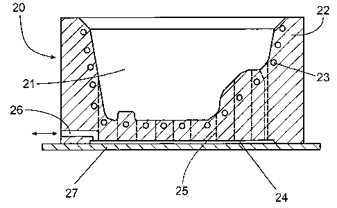
Figure 4 illustrates a detail of a part shaped
according to the present invention with a mold similar to
Figure 2. The part 150 has an external wall 151 with a
good surface finish obtained from the conformation to the
rigid wall 160 of the female section of the mold 20. The
internal wall 152, 155 has a good surface finish in a first
portion 152 corresponding to the external wall 157 of the
punch 7, and a rougher surface finish in a second portion
155, corresponding to the external wall 158 of the flexible
elastomer diaphragm 6. The seam 154 between the punch 7
and the flexible elastomer diaphragm 6 leaves a clear mark
153 between the first portion 152 and the second portion
154. These portions 152, 154 and mark 153 are indications
that this product has been made from the apparatus and
method according to the present invention.
In the example illustrated in Figure 4, all the
exterior walls 151 of the part have good surface finish.
Bottom section 152 of the internal wall of the part,
obtained by the stamping action of the stamping plate 7
CA 02473692 2004-07-16
WO 03/061930 PCT/CA03/00051
- 23 -
also has a good surface finish. The good surface finish of
the internal wall of the part can be located as needed by
changing the location of the stamping plate 157.
Preferably, the stamping plate 157 is located in order to
pull the sheet inside the female section of the mold 20 to
cause limited displacement (inflation) of the flexible
elastomer diaphragm 6. When nuts and bolts 12 are used to
fasten the stamping plate 7 and the flexible elastomer
diaphragm 6 to the rigid sub-structure 3, the presence of
the fastener head 158 at the surface of the stamping plate
157 is another distinctive mark left on a product obtained
by the apparatus and method of the present invention. The
good surface finish is inverted when the product is
obtained using the apparatus illustrated on Figure 3. In
this situation all the internal walls of the part have good
surface finish and a section of the external walls obtained
by the stamping action of the stamping plate has a good
surface finish. The mark by the fastener is then on this
external wall portion of the part.
Figure 5 shows an overall view of the mold 251, the
composite laminate 227 and the laminate clamping system
composed of the clamping supports and the support frame.
Referring to Figure 5, a support system 200 comprises a
support frame 250 and a set of clamping support 201. Each
individual clamping support 201 follows the movements of
the laminate periphery 226 during the molding phase, and
these movements depend on the geometry of the mold.
Indeed, the translation and rotation of each support
depends on the movements of the laminate fibres 227
(oriented at pre-defined angles), which are subject to the
mold 251 geometry.
CA 02473692 2004-07-16
WO 03/061930 PCT/CA03/00051
- 24 -
To optimize sheet size and permit molding of large
parts while minimizing material loss, the space occupied by
the clamping system inside the press support frame and the
clamping surface (the laminate surface inside the clamps)
must be minimized. The supports must be able to sustain
the high temperatures of the oven. The tension forces
induced on the laminate by the clamping supports have to be
adjustable to the desired intensity to allow proper re-
orientation of the fibres in the laminate during molding to
avoid wrinkles formation in the part. Also, because
wrinkle formation depends on part configuration, the force
needed from each support may be different. In other words,
the membrane forces can be adjustable on each support, and
these forces can be different from support to support
depending on the mold geometry.
Referring to Figure 6, a clamping support 201 has an
inverted L-shaped body 209 having a horizontal top portion
made of a tube section, shown in the example as a
rectangular tube section; a vertical section made of a
least one plate is also included. A plurality of
telescoping tubes, 210 and 211, are inserted in the tube
section of the body 209, to form a telescopic translation
system.
A bracket 206 attaches the clamping support 201 to the
press support frame 250. The bracket 206 is joined to the
body 209 by an universal joint 207 and 213 (Figure 7),
having pivot 213 (shown in the cut on Figure 7) to provide
rotation about a vertical axis or Y-axis, and a second
pivot axis parallel to the portion of the support frame 250
over which bracket 206 is attached, perpendicular to the
first axis.
CA 02473692 2004-07-16
WO 03/061930 PCT/CA03/00051
- 25 -
A stabilizing compression spring 216, acts as
suspension to stabilize the support 201 during the forming
step and when no external force is applied to the support.
Spring 216 stabilizes support 201 movement around the Z-
axis against abrupt changes. The compression spring 216
also precludes premature cooling of the sheet over the top
flat region around the aluminium cavity. This is achieved
by keeping the sheet upward the portion of the laminate
outside the mold during molding, while still allowing
rotation of the support around the Z and Y-axis by sliding
over the mounting bracket 206. The compression spring 216
is attached at its top portion to the body 209, and the
bottom portion slides freely over the bracket to allow the
Y-axis rotations around the pivot 213.
A jaw system of the support 201 comprises a jaw
assembly 202-205 having at the bottom a fixed jaw portion
205. The system provides a vertical frame portion 204
having attached them to the frame portion 204 is fixed to
tube 211. The fixed jaw portion 205 cooperates with a
pivoting jaw 203 to retain a peripheral portion of a
laminate 225. The pneumatic piston 202 and the pivoting
jaw 203 allows composite sheet loading on the supports.
The rotation of these components about their respective
pivot, increases the clearance necessary to easily install
the sheet from the top of the supports, with the open
version depicted in Figure 7.
Cylinder 202 and the jaw assembly 205 are movable in
the X direction via tubes 210-211. Tube 211 is fixed at
one end to the jaw assembly 204-205 and is slidable inside
tube 210, which in turn is slidable in the tube portion of
body 209. During formation, support 201 follows the
laminate translation along the X-axis via the tubes 210-211
CA 02473692 2004-07-16
WO 03/061930 PCT/CA03/00051
- 26 -
sliding one into the other and into the tube section of the
body 209.
A tensioning system 220-221 includes a cable 221 and a
winding device 220. A braking system 224 is provided to
control abrupt changes in tension or to increase tension.
In Figure 6 and 7, the tensioning system shown is a
constant force spring made of a flat steel strip enrolled
on itself and commercially available under different sizes
and forces. Tensioning springs inside the winding device
220 provide application of a constant force during the
formation phase and during the return of the support to its
initial position. These actions are conducted without any
external control, except for the action of the pneumatic
piston 202. This makes the system work very efficiently
and easily, even at high oven temperatures. The tensioning
springs 220-221 can be interchanged or combined with
springs of different forces, on the same support or on
different supports distributed around the composite sheet
to allow adjustment of the membrane tension over the
composite sheet necessary to insure a good conformation
during the forming phase. This means that the supports
located along the sides of the composite sheet can be
mounted with different tension springs. In the event that
larger membrane forces are needed to stretch the composite
sheet or if smooth variations of the loads are needed
during supports translations along the X-axis, braking
system 224 installed between the plates of the body 209 in
front of the spring and on each side of the strip can be
designed and installed on the support. Such a system could
be externally controlled by a computer (not shown) or made
simple via the use of friction pads mounted with adjustable
compression springs.
CA 02473692 2004-07-16
WO 03/061930 PCT/CA03/00051
- 27 -
A locking conical head screw (not shown) installed in
one of the holes 222 facilitates limited translation
movements along the X-axis. This type of stop avoids
damage to the mold and supports during mold closure. The
provision of several holes permits adjustment of
translation distance.
Referring back to Figure 6, in operation, the first
step is to clamp the laminate to a set of supports 201. To
clamp the laminate, the pneumatic cylinder 202 activates
the jaw 203 rotating around a pivot point 217 located at
the base of the jaw-assembly. When all supports are
closed, the whole clamping system and the laminate are
moved inside an oven (not shown) for the heating of the
laminate and the melting of the thermoplastic matrix of the
laminate.
The second step is to preheat the laminate to the
desired temperature in the oven, and then position the
preheated laminate over the mold, ready for forming. The
third step is the formation process, which may be a known
formation technique or the formation technique developed in
the present invention. During the formation step, supports
201 follow the laminate using the tubes 210 and 211 for
translation movements and the universal joint 207 and 213
for rotation movement. The support system 200 also
maintains a pre-determined tension on the laminate, using
the tension springs 220 and 221. Once the part is formed,
the mold is re-opened. At this point, the tension from the
support system 200 assists the de-molding or removal step
and the molded part is discharged from the mold. As soon
as the part is unclamped, tension springs 220 and 221 of
each clamping support 201 force the sliding tubes 210 and
211, to retract into one another and into body 209. This
CA 02473692 2004-07-16
WO 03/061930 PCT/CA03/00051
- 28 -
places the clamps near the sides of the press frame, ready
to begin another molding cycle.
Referring to Figure 8, an alternative solution of the
support can be used when there is a concern about an
obstruction caused by the jaw assembly 202-205. This is
particularly important to reduce the obstruction when the
press frame moves from the oven to the top of the mold with
the inherent risk of collision with adjacent equipment. It
is also possible, with this system, to minimize the space
occupied by the jaw-assembly 202-205 of the preceding
support system inside the press-support frame 250 and thus
maximize the size of the part that can be molded. The
system is based on the use of the same kind of constant
force springs to apply the membrane force on the composite
sheet but with a much smaller clamping device.
The clamping device has an L-shaped clamp 304 rotating
around a pivot point located at the corner of the L shape
and inside a quarter-cylinder metallic enclosure 301.
Inside the enclosure 301, an inflatable diaphragm 302
mounted with an inlet valve at the rear of the enclosure
301 is installed with an air inlet tubing 303 allowing the
diaphragm to inflate under pressure and deflate under
vacuum. The extremity of the strip of the constant force
spring, mounted at the rear and inside the outer tube, is
clamped near the base of the enclosure 301 with a small
clamping plate 305. A reinforcing plate 306, mounted under
the inner sliding tube below the clamping device, serves
also as a stopper to the moving sliding tubes (after
unclamping the part) when contacting the extremity of the
outer tube 312. It also serves as a mounting plate for
torsion springs 308 located on both sides of the clamp,304.
These springs, combined with a simultaneous vacuum applied
CA 02473692 2004-07-16
WO 03/061930 PCT/CA03/00051
- 29 -
inside the diaphragm 302, are used to unclamp the composite
sheet 307 by rotation of the clamp 304 inside the enclosure
301. Similar to the first embodiment shown in Figure 6, a
free space 309, located in front of the constant force
spring 311 and inside the outer tube 312, can be used to
mount a braking system for the steel strip of the constant
force spring in order to increase the membrane force on the
composite sheet 307.
Operation of the system involves application of a
vacuum inside the diaphragm 302 via the flexible tubing
303. The deflation of the diaphragm 302, combined with the
action of the torsion springs 308 forces the L-shaped clamp
304 to open. The composite sheet in then installed over
the supports arrangement, in similar fashion as shown in
Figure 5. Once the composite sheet is in place, the vacuum
inside the diaphragm 302 is pressurized, to rotate the
clamp 304 and clamp the composite sheet. The press support
frame is then moved into the oven for the melting of the
composite sheet. To avoid damaging the clamping support,
air inlet tubing 303 must be made of a flexible steel
pneumatic cable. Also, the cylindrical enclosure 301 can
be made of aluminium or steel in order to avoid damages to
the diaphragm by the infrared heating system of the oven.
During molding, the constant force spring applies a
membrane force on the composite sheet 307, similar to the
system of Figure 6. Once the part is formed, the pressure
inside the diaphragm is relieved to a vacuum to unclamp the
part. Once unclamped, the constant force spring forces the
sliding tubes to enter one into the other, placing the
clamps near the sides of the press frame, ready to begin
another molding cycle.
CA 02473692 2004-07-16
WO 03/061930 PCT/CA03/00051
- 30 -
The main advantage of this system is its compactness,
allowing the maximum space inside the press frame to
support a maximum size composite sheet. The excess space
over and under the press frame taken by the clamping system
is also minimized, thus minimizing any obstruction of the
support with the surrounding equipments and the tooling.
This advantage is important since material lost is
minimized.
It will be understood that the invention may be used
with any thermoformable material sheet and that the
continuous fibre reinforced thermoplastic is illustrated
herein only as an example. The present invention is not
limited to the sole embodiment described above, but
encompasses any and all embodiments within the scope of the
following claims.