Sélection de la langue

Search

Sommaire du brevet 2473764 

Énoncé de désistement de responsabilité concernant l'information provenant de tiers

Une partie des informations de ce site Web a été fournie par des sources externes. Le gouvernement du Canada n'assume aucune responsabilité concernant la précision, l'actualité ou la fiabilité des informations fournies par les sources externes. Les utilisateurs qui désirent employer cette information devraient consulter directement la source des informations. Le contenu fourni par les sources externes n'est pas assujetti aux exigences sur les langues officielles, la protection des renseignements personnels et l'accessibilité.

Disponibilité de l'Abrégé et des Revendications

L'apparition de différences dans le texte et l'image des Revendications et de l'Abrégé dépend du moment auquel le document est publié. Les textes des Revendications et de l'Abrégé sont affichés :

  • lorsque la demande peut être examinée par le public;
  • lorsque le brevet est émis (délivrance).
(12) Demande de brevet: (11) CA 2473764
(54) Titre français: METHODE ET DISPOSITIF DE REGLAGE DE HAUTEUR D'UN COUVRE-FENETRE PAR ROTOR MOBILE
(54) Titre anglais: WINDOW COVERING HEIGHT ADJUSTMENT METHOD AND APPARATUS USING TRAVELING ROTOR
Statut: Réputée abandonnée et au-delà du délai pour le rétablissement - en attente de la réponse à l’avis de communication rejetée
Données bibliographiques
(51) Classification internationale des brevets (CIB):
  • E06B 9/322 (2006.01)
  • E06B 9/262 (2006.01)
(72) Inventeurs :
  • CHENG, LI-MING (Chine)
  • WU, LAWRENCE S. (Etats-Unis d'Amérique)
(73) Titulaires :
  • ZIPSHADE INDUSTRIAL (B.V.I.) CORP.
(71) Demandeurs :
  • ZIPSHADE INDUSTRIAL (B.V.I.) CORP. (Etats-Unis d'Amérique)
(74) Agent: SMART & BIGGAR LP
(74) Co-agent:
(45) Délivré:
(22) Date de dépôt: 2004-07-12
(41) Mise à la disponibilité du public: 2006-01-12
Licence disponible: S.O.
Cédé au domaine public: S.O.
(25) Langue des documents déposés: Anglais

Traité de coopération en matière de brevets (PCT): Non

(30) Données de priorité de la demande: S.O.

Abrégés

Abrégé anglais


A method of controlling the vertical height of
a window shade having a top and bottom, which includes
providing shade upper support structure at or proximate
the shade top; providing at least one substantially
vertically elongated shade support line extending
downwardly from the upper support structure, and
providing shade lower support structure at or proximate
the shade bottom; elevating or lowering the shade lower
support structure relative to one or more support lines;
and securing the shade lower support structure to the
line or lines at a selected height position relative to
the line length above the lower support structure,
whereby the height of the shade bottom can be quickly
manually adjusted by adjustment of the height of the
shade lower support structure effective securement to
line or lines.

Revendications

Note : Les revendications sont présentées dans la langue officielle dans laquelle elles ont été soumises.


WE CLAIM:
1. The method of controlling the vertical
height of a window shade having a top and bottom, which
includes the steps
a) providing shade upper support structure
at or proximate the shade top,
b) providing at least one substantially
vertically elongated shade support line extending
downwardly from said upper support structure,
c) and providing shade lower support
structure at or proximate the shade bottom,
d) elevating or lowering said shade lower
support structure relative to said one or more support
lines,
e) and effectively securing said shade lower
support structure to the line or lines at a selected
height position relative to the line length above said
lower support structure,
f) said securing including effecting
adjustable wrapping of the line or lines about a rotary
drum or drums provided and positioned at said lower
support structure,
11

g) said shade lower support structure being
a vertically relatively thin slat having at least one
vertical through opening to pass said at least one shade
support line.
h) the entirety or entireties of said drum
or drums located below and substantially adjacent said
slat.
i) whereby the height of the shade bottom can
be quickly manually adjusted by adjustment of the height
of the shade lower support structure.
2. The method of claim 1 wherein said shade
is provided in the form of a sequence of pleats, and
said line or lines is or are located adjacent said
pleats.
3. The method of claim 1 wherein the weight
of the lowermost extent of the shade is carried by said
shade lower support structure as said lower support
12

structure is elevated to shorten the height of the
shade.
4. The method of claim 1 including encasing
said drum or drums in a housing or housings, and
supporting said shade lower support structure on said
housing or housings, the overall heights of each drum
housing or housings exceeding the vertical thickness of
the slat.
5. The method of claim 4 including locating
said housings at laterally spaced locations each
directly beneath said lower support structure.
6. The method of claim 5 including providing
a spring or springs associated with said drum or drums,
and acting to urge said drum or drums in rotary
direction to wind said line or lines.
13

7. The method of claim 4 including providing
support shoulders on upper extents of said housing or
housings to engage lowermost surfaces of said lower
support structure, and acting to orient said housings
relative to said shade support structure.
8. The method of claim 4 including attaching
said housing or housings to said shade lowermost support:
structure.
9. The method of claim 8 including providing
a manipulable line gripping stop in association with
each housing, to grip the line in shade height adjusted
position, and to loosen the line for winding or
unwinding as the shade height is adjusted.
10. The method of controlling the vertical
height of a window shade having a top and bottom, and
pleats therebetween which includes the steps
a) providing shade upper support structure
at or proximate the shade top,
14

b) providing at least one substantially
vertically elongated shade support line extending
downwardly from said upper support structure,
c) and providing shade lower support
structure in the form of a substantially horizontally
extending slat for supporting pleats gathered or
gathering at or proximate the shade bottom,
d) elevating or lowering said shade lower
support structure relative to said one or more support
lines,
e) and effectively securing said shade lower
support structure to the line or lines at a selected
height position relative to the line length above said
lower support structure, by providing a holder or
holders entirely below said slat or and by which said
line or lines are adjustably held, below said slat,
f) whereby the height of the shade bottom
can be quickly manually adjusted by adjustment of the
height of the shade lower support structure.
11. The method of claim 10 wherein said shade
is provided in the form of a sequence of said pleats,
and said line or lines is or are located adjacent said

pleats and passing through said pleats at locations in
vertical alignment with said stop or stops.
12. The method of claim 10 wherein weight
imposed by the lowermost pleats of the shade is carried
by said shade lower support structure as said lower
support structure is elevated to shorten the height of
the shade.
13. The method of claim 10 wherein lowermost
extent of the line or lines is or are extended below
said lower support structures and including supporting
said lowermost extent of the line or lines at a location
or locations characterized in that said lowermost extent
of the line or lines remains extended below said slat.
14. The method of claim 10 wherein said
holder or holders have slidable engagement with and
being adjustable along the line length in response to
manual manipulation of said holder or holders.
16

15. The method of controlling the vertical
height of a window shade having a top and bottom, which
includes the steps
a) providing shade upper support structure
at or proximate the shade top,
b) providing at least one substantially
vertically elongated shade support line extending
downwardly from said upper support structure,
c) and providing shade lower support
structure at or proximate the shade bottom,
d) elevating or lowering said shade lower
support structure relative to said one or more support
lines,
e) and effectively securing said shade lower
support structure to the line or lines at a selected
height position relative to the line length above said
lower support structure,
f) said securing including effecting
attachment of the line or lines to a support or support
entirely below a slat defined by said lower support
structure,
g) whereby the height of the shade bottom
can be quickly manually adjusted by adjustment of the
height of the shade lower support structure.
17

16. The method of claim 15 wherein said shade
is provided in the form of a sequence of pleats, and
said line or lines is or are located adjacent said
pleats.
17. The method of claim 15 wherein the weight
of the lowermost extent of the shade is carried by said
shade lower support structure as sand lower support
structure is elevated to shorten the height of the
shade.
18. The method of claim 15 including
employing multiple lines to support the shade lowermost
support structure, said lines transferring loading to
said supports.
19. The method of claim 15 including
providing a spring associated with said support or
supports.
18

20. The method of claim 15 wherein there are
two of said supports, each defining holding mechanism.
21. Apparatus for controlling the vertical
height of a window shade having a tap and bottom, which
includes
a) shade upper support structure at or
proximate the shade top,
b) at least one substantially vertically
elongated shade support line extending downwardly from
said upper support structure,
c) and shade lower support structure at or
proximate the shade bottom,
d) said apparatus adapted for elevating or
lowering said shade lower support structure relative to
said one or more support line,
e) a securing device for effectively
securing said shade lower support structure to the line
or lines at a selected height position relative to the
line length above said lower support structure, said
securing device effecting attachment of the line at a
support below the level of said lower support structure,
19

g) whereby the height of the shade bottom
can be quickly manually adjusted by adjustment of the
height of the shade lower support structure effective
securement to said line or lines.
20

Description

Note : Les descriptions sont présentées dans la langue officielle dans laquelle elles ont été soumises.

CA 02473764 2004-07-12
BACKGROUNb OF THE INVENTION
This invention relates generally to control or
adjustment of window coverings, and more particularly to
ease and efficiency of window covering height
adjustment. Such window coverings are referred to as
shades, or blinds, or window coverings generally, and
may be formed by pleats of a single piece of material,
o.r by other configuration.
There is need for improvements in
adjustability of such coverings or shades, as for
example where the effective window covering height of
the shade is to be adjusted. zn the past, pleated
shades were suspended by their own material, i.e. were
allowed to hang, causing the weight of the shade to
expand the pleats. It was then difficult to accurately
adjust shade height, since over time the shade weight
could expand the pleats, changing the overall height of
the shade. Such pleated shades typically consisted of
paper. Also venetian blinds and all window coverings
require raising and lowering functions.
2

~
CA 02473764 2004-07-12
SUMMARY OF THE INVENTTON
It is a major object of the invention to
provide an easily adjustable means al).owing shade height
adjustment, and where only a minimum number of shade
supporting lines are required.
Basically, the improvement comprisEs
aj upper support structure at or proximate
the shade top,
b) at least one substanti<311y vertically
elongated shade support line extending downwardly from
said upper support structure,
c) shade Lower support structure at or
proximate the shade bottom,
and shade adjustment includes:
d) elevating or lowering the shade lower
support structure relative to the one or more support
lines,
e) and effectively securing the shade lower
support structure to the line or lines at a selected
height position relative to the line length,
f) said securing including effecting
adjustable wrapping of the line or lines about a rotary
3

CA 02473764 2004-07-12
drum or drums provided and positioned at said lower
support structure, to travel therewith,
g) whereby the height of the shade bottom
can be quickly manually adjusted by adjustment of the
height of the shade lower support structure,
As will appear, the shade is typically
provided in the form of a sequence of pleats, and the
line or lines is or are located adjacent such pleats.
Another object includes prouisian for weight
of the lowermost extent of the shade to be carried by
the shade lower support structure as that lower support
structure is elevated to shorten the height of the
shade. As the shade lower support structure is adjusted
upwardly, the line below that support structure is
typically wound automatically by a traveling drum or
drums associated with and below the lowermost support
structure..
A further object i.s to pravidP fir Rncasing
the drum or drums in a housing or housings, and
supporting the shade lower support structure on the
housing ar housings.
The housings are typically located at
laterally spaced locations and directly beneath or
inside the 7owPr suppn.rt structure.

CA 02473764 2004-07-12
Another object includes pravia ion of a spring
or springs associated with th.e drum or drums, and acting
to urge the drum ar drums in rotary direct.ian to
automatically wind the line or lines.
A further object includes provision of a
support shnu'lder an upper extent of, said housing or
housings to engage lowermost surfaces of the lower
support structure, and acting to orient said housing or
housings relative tn said shade support strur_ture td
20 enable line winding.
An additional object includes provision of a
manipulahlP line gripping stop, in aysor_iatinn with aarh
housing, to grip the line in shade height adjusted
position, and to loosen the Line for winding or
7 .5 unwi nc3i ng as the shade hPi ght i s adjiasred .
These and other objects and advantages of the
invention, as well as the details of an illustrative
embodiment, will be more fully under:>tood from the'
following specification and drawings" in which:
DRAWING DESCRIPTION
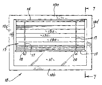
Fig. 1 is an elevation shooting an adjustably
supported window shade;
5

i.
CA 02473764 2004-07-12
Fig. 2 is an enlarged elevational view,
showing use of a line wrapping device below the shade
lowermost suppoxt portion;
Fig. 3 is a view showing line wrapping drum
and spring structure;
Fig_ a is an enlarged diagrammatic view
showing shade lowering;
Fig. 5 is a view like Fig. ~ showing shade
raising;
1o Figs. 6 and 6a_ are elevational view showing
shade full lowering and shade partial raising;
Fig_ 7 is an end elevation taken on lines 7-7
of Fig. 1; and
Fig. 8 shows a line providing drum in a case,
with a finger control to engage a lina_.
DETAILED DESCRIPTION
In Fig. 1, shade upper support structure is
shown at 10, as in the form of a horizontal upper part
~.oa of a window frame. ThP frame also includes frame
lower part lOb, and verticals at 1oc and 10d. The
window may for example include a glass pane 12.
6

CA 02473764 2004-07-12
A window shade or cover is shown at 13, and
may include pleats 13a, which expand apart to extend
diagonally back and forth, when the shade is hung. An
upper shade support structure is located at or proximate
the shade top. See far example horizontal slat 1~ the
uppex side of which may ba attached to the frame part
loo, as for example by tape having adhesive at its
opposite sides.
At least one, and prefErably twn support line.
or cords 1? are suspended from slat 3.4, the two
illustrated lines 1? being spaced about horiaantally.
Those 7inec pass dawnwardly through holes in the pleats,
as seen in Fig_ ?, and they also pass downwaxdly loosely
through holes or openings 18 in a shade lower support
strur_t~a.re located at or proximate the shade bottom. As
shown, the lower support structure comprises a
horizontally elongated lower slat 19. The uppermost
pleat l3aa may be attached to the underside of the upper
slat 1~; and the lowermost pleat l3bb may be attached to
the upper side of the lower slat 19_ The attachments
may be made by use of dual adhesive sided tape.
The shade height may therefore be adjusted by
manually elevating or lowering the lower slat 19,
7

CA 02473764 2004-07-12
relative to the line or lines 17, and securing it in
adjusted position.
such securing is preferably made by travP7ing
line wrapping adjusting device or devices 20, whereby
the lower slat 19 is held in selected elevated position
by those devices 20. As shown in Fig.. 2, the plat 19
seats on device 20, and the cord lower. extent 17c is
automatically wrapped on a drum 21 in a case 32, of
device 20. See Fig. 3, The preferred methad of ass
includes:
d) elevating or lowering the shade lower
support structure relative to one or more cuppnrt lines,
e) and effectively securing the shade lower
support structure to the line or lines at a selected
height position relative to the line length above that
lower support structure,
f) such securing including effecting
adjustable wrapping of the line or lines about a .rotary
drum or drums provided and positioned at that lower
support structure to travel therewith,
whereby the height of the shade bottom
can be quickly manually adjusted by adjustment of the
height of the shade lower support structure.
8

CA 02473764 2004-07-12
Figs. 2 and 3 show a rotary drum 21 on a shaft
31 carried inside a case or housing 32. The latter is
located adjacent the slat 19, so that line 17 enters the
housing at 33, and winds on the drum. The case is
typically located just below slat 19, and is carried by
the slat. An abutment 34 may be carried by the cace, t~
have its upper flat side 34a in engagement with the
lower side 19a of the slat 19.
A spring 35 in the case urg~_s drum in a .rotary
1o direction tending to wind up the line 17 on the drum.
Accordingly as the slat 19 is raised, as by hand, the
case 32 moves up, and the drum winds up the line that:
would otherwise dangle. Note coil spring turned ends
35a and 35b connected to the case and to the drum.
Likewise, as slot 19 is pulled down, or lowered, the
drum 21 rotates to spool off the amount of line 17, to
accommodate such lowering.
If need be, a line gripping stop or control 40
may be provided, as shown in fig. 8, to grip the drum,
in adjusted position of the slat 19. See for example
Sever 4o urged by a spring 41 to grip the drum flange
21a, and released by finger pressure to allow drum
rotation.
9

CA 02473764 2004-07-12
Fig. 4 schematically shows the operation of
shade lowering; and Fig. 5 schematically shows the
operation of shade raising to gather pleats. Fig. 6
shows two casings 20 spaced apart laterally below such
lower slot 19, to support the shade in lowered position.
Lines 17 extending above the drums wind up on drums
within the casings as the shade lower slat l9 is raised.
Fig. 6a shows the two casings, during raising of the
shade.
15

Dessin représentatif
Une figure unique qui représente un dessin illustrant l'invention.
États administratifs

2024-08-01 : Dans le cadre de la transition vers les Brevets de nouvelle génération (BNG), la base de données sur les brevets canadiens (BDBC) contient désormais un Historique d'événement plus détaillé, qui reproduit le Journal des événements de notre nouvelle solution interne.

Veuillez noter que les événements débutant par « Inactive : » se réfèrent à des événements qui ne sont plus utilisés dans notre nouvelle solution interne.

Pour une meilleure compréhension de l'état de la demande ou brevet qui figure sur cette page, la rubrique Mise en garde , et les descriptions de Brevet , Historique d'événement , Taxes périodiques et Historique des paiements devraient être consultées.

Historique d'événement

Description Date
Le délai pour l'annulation est expiré 2010-07-12
Demande non rétablie avant l'échéance 2010-07-12
Inactive : Abandon.-RE+surtaxe impayées-Corr envoyée 2009-07-13
Réputée abandonnée - omission de répondre à un avis sur les taxes pour le maintien en état 2009-07-13
Lettre envoyée 2008-08-25
Demande publiée (accessible au public) 2006-01-12
Inactive : Page couverture publiée 2006-01-11
Lettre envoyée 2004-10-01
Inactive : CIB en 1re position 2004-09-29
Inactive : CIB attribuée 2004-09-29
Inactive : Transfert individuel 2004-08-30
Inactive : Lettre de courtoisie - Preuve 2004-08-24
Demande reçue - nationale ordinaire 2004-08-19
Exigences de dépôt - jugé conforme 2004-08-19
Inactive : Certificat de dépôt - Sans RE (Anglais) 2004-08-19

Historique d'abandonnement

Date d'abandonnement Raison Date de rétablissement
2009-07-13

Taxes périodiques

Le dernier paiement a été reçu le 2008-07-14

Avis : Si le paiement en totalité n'a pas été reçu au plus tard à la date indiquée, une taxe supplémentaire peut être imposée, soit une des taxes suivantes :

  • taxe de rétablissement ;
  • taxe pour paiement en souffrance ; ou
  • taxe additionnelle pour le renversement d'une péremption réputée.

Veuillez vous référer à la page web des taxes sur les brevets de l'OPIC pour voir tous les montants actuels des taxes.

Historique des taxes

Type de taxes Anniversaire Échéance Date payée
Taxe pour le dépôt - générale 2004-07-12
Enregistrement d'un document 2004-08-30
TM (demande, 2e anniv.) - générale 02 2006-07-12 2006-07-10
TM (demande, 3e anniv.) - générale 03 2007-07-12 2007-07-04
2008-07-04
TM (demande, 4e anniv.) - générale 04 2008-07-14 2008-07-14
Titulaires au dossier

Les titulaires actuels et antérieures au dossier sont affichés en ordre alphabétique.

Titulaires actuels au dossier
ZIPSHADE INDUSTRIAL (B.V.I.) CORP.
Titulaires antérieures au dossier
LAWRENCE S. WU
LI-MING CHENG
Les propriétaires antérieurs qui ne figurent pas dans la liste des « Propriétaires au dossier » apparaîtront dans d'autres documents au dossier.
Documents

Pour visionner les fichiers sélectionnés, entrer le code reCAPTCHA :


Pour visualiser une image, cliquer sur un lien dans la colonne description du document. Pour télécharger l'image (les images), cliquer l'une ou plusieurs cases à cocher dans la première colonne et ensuite cliquer sur le bouton "Télécharger sélection en format PDF (archive Zip)" ou le bouton "Télécharger sélection (en un fichier PDF fusionné)".

Liste des documents de brevet publiés et non publiés sur la BDBC .

Si vous avez des difficultés à accéder au contenu, veuillez communiquer avec le Centre de services à la clientèle au 1-866-997-1936, ou envoyer un courriel au Centre de service à la clientèle de l'OPIC.


Description du
Document 
Date
(aaaa-mm-jj) 
Nombre de pages   Taille de l'image (Ko) 
Abrégé 2004-07-12 1 26
Description 2004-07-12 9 257
Revendications 2004-07-12 10 240
Dessins 2004-07-12 5 129
Dessin représentatif 2005-12-15 1 16
Page couverture 2005-12-22 1 48
Certificat de dépôt (anglais) 2004-08-19 1 158
Courtoisie - Certificat d'enregistrement (document(s) connexe(s)) 2004-10-01 1 129
Rappel de taxe de maintien due 2006-03-14 1 111
Rappel - requête d'examen 2009-03-16 1 117
Courtoisie - Lettre d'abandon (taxe de maintien en état) 2009-09-08 1 172
Courtoisie - Lettre d'abandon (requête d'examen) 2009-10-19 1 165
Correspondance 2004-08-19 1 27
Taxes 2006-07-10 1 37
Taxes 2007-07-04 1 36
Correspondance 2008-08-25 1 23
Taxes 2008-07-14 1 37
Taxes 2008-07-04 1 29