Sélection de la langue

Search

Sommaire du brevet 2473777 

Énoncé de désistement de responsabilité concernant l'information provenant de tiers

Une partie des informations de ce site Web a été fournie par des sources externes. Le gouvernement du Canada n'assume aucune responsabilité concernant la précision, l'actualité ou la fiabilité des informations fournies par les sources externes. Les utilisateurs qui désirent employer cette information devraient consulter directement la source des informations. Le contenu fourni par les sources externes n'est pas assujetti aux exigences sur les langues officielles, la protection des renseignements personnels et l'accessibilité.

Disponibilité de l'Abrégé et des Revendications

L'apparition de différences dans le texte et l'image des Revendications et de l'Abrégé dépend du moment auquel le document est publié. Les textes des Revendications et de l'Abrégé sont affichés :

  • lorsque la demande peut être examinée par le public;
  • lorsque le brevet est émis (délivrance).
(12) Brevet: (11) CA 2473777
(54) Titre français: PROCEDE ET DISPOSITIFS DE FABRICATION DE PIECES RENFORCEES PAR DES FIBRES
(54) Titre anglais: METHOD AND DEVICES FOR PRODUCING FIBRE-REINFORCED COMPONENTS
Statut: Durée expirée - au-delà du délai suivant l'octroi
Données bibliographiques
(51) Classification internationale des brevets (CIB):
  • B29C 70/54 (2006.01)
  • B29C 70/44 (2006.01)
(72) Inventeurs :
  • LIPPERT, THOMAS (Allemagne)
  • SCHROEDER, HANS-WOLFGANG (Allemagne)
  • STADLER, FRANZ (Allemagne)
  • UTECHT, STEFAN (Allemagne)
(73) Titulaires :
  • AIRBUS DEFENCE AND SPACE GMBH
(71) Demandeurs :
  • AIRBUS DEFENCE AND SPACE GMBH (Allemagne)
(74) Agent: BORDEN LADNER GERVAIS LLP
(74) Co-agent:
(45) Délivré: 2010-07-27
(86) Date de dépôt PCT: 2003-01-23
(87) Mise à la disponibilité du public: 2003-08-07
Requête d'examen: 2007-06-15
Licence disponible: S.O.
Cédé au domaine public: S.O.
(25) Langue des documents déposés: Anglais

Traité de coopération en matière de brevets (PCT): Oui
(86) Numéro de la demande PCT: PCT/DE2003/000177
(87) Numéro de publication internationale PCT: DE2003000177
(85) Entrée nationale: 2004-07-20

(30) Données de priorité de la demande:
Numéro de la demande Pays / territoire Date
102 03 975.5 (Allemagne) 2002-01-31

Abrégés

Abrégé français

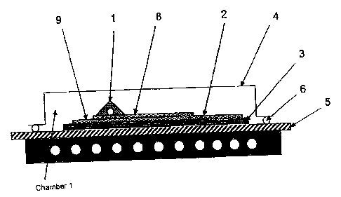
Structure d'injection contenant un produit semi-fini (3) renforcé par des fibres pour la fabrication d'une pièce renforcée par des fibres, qui comporte un dispositif d'injection (1) destinée à l'introduction de matière matrice, une toile de répartition (8) et une couche barrière (9) imperméable à la matière matrice. La toile de répartition (8) est placée entre le dispositif d'injection (1) et le produit semi-fini (3) renforcé par des fibres et la couche barrière (9) est placée entre la toile de répartition (8) et le produit semi-fini (3) renforcé par des fibres. La présente invention concerne également un dispositif de fabrication d'une pièce renforcée par des fibres à l'aide de cette structure d'injection.


Abrégé anglais


The invention relates to an injection-structure containing a fibre reinforced
semi-finished product (3) in order to produce a fibre reinforced component,
which comprises an injection device (1) used to introduce matrix material, a
distributing fabric (8) and an impermeable blocking layer (9) for the matrix
material. The distributing fabric (8) is disposed between the injection device
(1) and the fibre-reinforced semi-finished product (3), and the blocking layer
(9) is disposed between the distributing fabric (8) and the fibre-reinforced
semi-finished product (3). The invention also relates to a device for
producing a fibre-reinforced component by means of said injection structure.

Revendications

Note : Les revendications sont présentées dans la langue officielle dans laquelle elles ont été soumises.


8
Claims
1. Injection structure with a fiber-composite semifinished product (3) for
manufacturing a fiber-composite component, having a gate device (1) for
feeding matrix material, a distribution fabric (8), and a barrier layer (9)
that
is impermeable to the matrix material, characterized in that the distribution
fabric (8) is arranged between the gate device (1) and the fiber-composite
semifinished product (3), and the barrier layer (9) is arranged between the
distribution fabric (8) and the fiber-composite semifinished product (3).
2. Injection structure with a fiber-composite semifinished product (3) for
manufacturing a fiber-composite component in accordance with claim 1,
characterized in that the distribution fabric (8) projects beyond the barrier
layer on at least one side.
3. Injection structure with a fiber-composite semifinished product (3) for
manufacturing a fiber-composite component in accordance with claim 1 or
2, characterized in that the barrier layer (9) is gas-permeable and matrix-
material-impermeable.
4. Injection structure with a fiber-composite semifinished product (3) for
manufacturing a fiber-composite component in accordance with one of the
preceding claims, characterized in that the barrier layer (9) is a film or
panel.
5. Injection structure with a fiber-composite semifinished product (3) for
manufacturing a fiber-composite component in accordance with one of the
preceding claims, characterized in that the barrier layer (9) is realized with

9
a PTFE film, an adhesive, and/or a backing fabric, or in the form of a
sandwich construction made from these materials.
6. Method for manufacturing a fiber-composite component from a fiber-
composite semifinished product (3), wherein matrix material is fed to a
structure in accordance with one of claims 1 to 4, the matrix material is
distributed through a distribution fabric (8) above the barrier layer (9) and
in the part of the distribution fabric projecting beyond the barrier layer so
that the matrix material arrives from the part of the distribution fabric
projecting beyond the barrier layer at the fiber-composite semifinished
product (3) and infiltrates it.

Description

Note : Les descriptions sont présentées dans la langue officielle dans laquelle elles ont été soumises.


CA 02473777 2004-07-20
1
Method and Devices for Producing Fiber-Reinforced Components
The invention relates to an injection structure in accordance with the
preamble to claim 1 and a method for producing fiber-reinforced plastic
components.
In the manufacture of fiber-composite components, hereinafter called FC
components, using resin injection methods, pores may be formed as a result of
gas bubbles, dissolved gases and other volatile constituents contained in the
matrix material. As a result, the quality of the components is reduced, to the
point
of unusability.
From German patent DE 100 13 409 C1 is a device and a process for
manufacturing fiber-reinforced plastic components from dry fiber-composite
semifinished products using an injection method for injecting matrix material
with
a gas-permeable and matrix-material-impermeable membrane, which is arranged
around the semifinished product on at least one side and forms a first space
and
into which matrix material can be introduced, having a flow promoter arranged
on
a surface of the semifinished product,. having a second space, sealed with
respect .to a tool, adjacent to the first space, which is delimited ~ from the
surroundings by means of a gas-impermeable and matrix-material-impermeable
film, wherein when air is removed from the second space by suction, matrix
material is drawn from the reservoir into the evacuated first space and the
flow
promoter causes distribution of the matrix material over the surtace of the
semifinished product facing it and penetration thereof vertically into the
semifinished product.
In this process, the matrix material is distributed by means of a flow
promoter over the fiber-composite semifinished product, and from there
penetrates the semifinished product. The flow promoter is delimited on one
side
by the gas-permeable and matrix-material-impermeable membrane. During

f',:~.
CA 02473777 2004-07-20
2
transport of the matrix material in the thin flow promoter, degassing of the
matrix
material takes place. The degassing takes place through the membrane
adjoining the flow promoter into the evacuated second chamber. For efficacious
degassing, it is necessary for the matrix material to first be able to travel
an
adequately long distance through the flow promoter before it enters the
semifinished product.
In the frequently used gate arrangements for introducing the matrix
material into the flow promoter, such film degassing does not occur directly
beneath the gates, and occurs only incompletely in the areas directly adjacent
thereto. Accordingly, the probability is greater beneath the gates and in the
areas
adjacent thereto that pore formation will take place there.
Another disadvantage of this process resides in that the use of two
chambers requires greater expenditure of auxiliary materials for 'the membrane
as compared to the single-chamber principle likewise known in fiber composite
technology.
In addition, degassing of the matrix material can take plaoe.according to a
method known from the general prior art wherein the matrix material is
remelted
into a thin layer (film) in an evacuated space. In general, the thinner the
matrix
material layer to be degassed, the more effective such a degassing process is.
This process for degassing the matrix material, which is also . called film
degassing, has the following disadvantages, for example:
- The additional degassing step is unfavorable with regard to costs and
additional inputs.
- The matrix material must be heated for the degassing step. This
causes aging processes to occur.

CA 02473777 2004-07-20
3
- The matrix material can again absorb volatile constituents, such as
water vapor from the air, prior to later processing to produce fiber-
composite components.
- The matrix material can react with auxiliary materials during the course
of the injection process, with the formation of gas. Thus, reactions with
low-cost, flexible silicone profiles for gates have been observed.
It is the object of the invention to provide a method and an injection
structure for manufacturing FC components in which or with which advantageous
degassing of matrix material occurs during the manufacture of FC components.
This object is attained with the features of the independent claims.
Additional embodiments are given in the subordinate claims.
In accordance with the invention, an injection structure with a fiber-
composite semifinished product is provided for manufacturing a fiber-composite
component, which has a gate device for feeding matrix material, a distribution
fabric, and a barrier layer that is impermeable to the matrix material,
wherein the
distribution fabric is arranged between the gate device and the fiber-
composite
semifinished product, and the barrier layer is arranged between the
distribution
fabric and the fiber-composite semifinished product.
In accordance with the invention, degassing is provided with the aid of a
matrix-material-impermeable auxiliary material or distribution fabric in
combination with a barrier layer placed between tile latter and the fiber-
composite semifinished product. Such a barrier layer can be realized with a
PTFE film, an adhesive, andlor a backing fabric, or in the form of a sandwich
construction made from these materials.
By this means, the probability of the occurrence of pores can be reduced
and, as a result, the ruggedness of the fabrication increased.

CA 02473777 2004-07-20
i...
4
The invention may be implemented in combination with the device andlor
the method from German patent DE 100 13 409 C1 or with other devices or
methods from the prior art. The invention may be used in combination with a
single-chamber structure and in combination with a dual-chamber structure.
The invention is explained below on the basis of the attached figures,
which shows:
- an exemplary injection structure with an embodiment of the
degassing device in accordance with the invention, wherein only a
first chamber of a dual-chamber structure of the injection structure
is shown in the frgure.
in accordance with the invention, a degassing device far the matrix
material used in the manufacture of FC components is provided. In one
embodiment of the invention, prior to entry or penetration into the nonwoven
textile fabric of fibers or reinforcing fibers to be infiltrated, the matrix
material is
degassed by means of at least one resin-impermeable film or barrier film in
combination with a distribution fabric or a flow promoter. This involves a
single-
layer or multi-layer film that do not allow the matrix material to pass. The
film may
allow gaseous constituents of the matrix material to pass or may be gas-
impermeable. This embodiment is in a structure with the fiber-composite
nonwoven fabric or a component production device with the nonwoven textile
fabric, i.e. it is integrated spatially in the structure with the fiber-
composite
nonwoven fabric.
In this context, material referred to as textile fabric is understood to be a
dry or pretreated fiber-composite fabric or nonwoven fabric from which a fiber-
composite component can be manufactured after resin infiltration and
aftertreatment in an autoclave.

CA 02473777 2004-07-20
S
In the embodiment shown in Figure 1 of the degassing device integrated
in a structure with the fiber-composite nonwoven fabric or a component
production device, the structure consists of at least two chambers wherein
only
one of the hero chambers, which is identified with reference symbol K1, is
shown
in Figure 1. Chamber K1 is separated from another chamber by a semi-
permeable film 4, which is gas-permeable and impermeable to resin or matrix
material. In this way, air can be withdrawn through the second chamber after
the
infiltration of resin into the first chamber K1. The invention may also be
used for a
single-chamber structure (not shown).
The structure shown in Fig. 1 with the fiber-composite nonwoven fabric or
injection structure comprises a gate device 1 or a feeder channel for resin,
an
additional degassing area distribution fabric or gate distribution fabric 8
and a
layer or barrier layer 9 - impermeable to the matrix material - in the form of
a film
or panel. The barrier layer 9 may be gas-permeable or gas-impermeable. The
gate distribution fabric 8 is located between the gate device 1 and the fiber
composite semifinished product 3. The barrier layer 9 is arranged between the
gate distribution fabric 8 and. the fiber-composite semifinished product 3.
The fiber-composite semifinished product 3 is placed on a mold 5 or
support device 5. A mold may be provided to form an outside of the fiber-
composite ' component to be manufactured. A support device 5 Can be a
supporting plate, for example. Preferably there is placed between the barrier
film
9 and the fiber-composite semifinished product 3 another distribution fabric,
which can be provided according to the prior art in order to distribute the
resin
over the fiber-composite semifinished product 3. The first chamber of the
structure from Figure 1 is formed by the film 4, which is sealed with respect
to the
mold or the support device 5 by means of a sealing strip 6.

6
The distribution fabric 8 preferably projects beyond the barrier layer 9 in
one direction (for example .direction L) or in multiple directions. In this
way, the
resin coming from the gate runner 1 and to be degassed can flow through the
distribution fabric 8 faang the latter, and because of the barrier layer 9 is
at first
not allowed to the fiber-composite nonwoven fabric. The distribufion fabric 8
is
placed in the region of the gate device 1. Not until the resin has reached the
region B, which overhangs rela4ve to the barrier layer 9, of the gate
distribution
fabric 8 can it arrive from there at the fiber-composite semifinished product
3 in
order to infiltrate it.
Such a barrier layer 9 can be realized with a PTFE film, an adhesive,
andlor a backing fabric, or in the form of a sandwich construction made from
these materials.
The flow promoter or the distribution fabric 2 between the fiber-composite
semifinished product 3 and the barrier layer 9 can be omitted in the structure
with
the fiber-composite semifinished product. The barrier layer 9 can be a film or
a
panel. As a panel, it can be composed of a metal sheet or another elastic or
rigid
tool.
During injection, the matrix material first flows through the gate device 1
into a degassing region located around the latter. Gas bubbles, dissolved
gases
and other volatile cons4tuents entrained by the matrix material can exit
through
the semi-permeable film 4 into the evacuated region (chamber 2 of the VAP
process).
The barrier layer 9 can, in particular, concern a semi-permeable film, i.e.
the film that is permeable to gases and impermeable to matrix material. Such a
semi-permeable film would. achieve additional degassing in the region of the
chamber 1 at the start of the injection process. ft is likewise possible to
use a
CA 02473777 2004-07-20

CA 02473777 2004-07-20
7
pressure plate as the barrier layer 9, as is required in any case in the
manufacture of some fiber-composite components.
The degassing distribution fabric 8 can, in special applications, also be
placed over the barrier layer 9 overlapping on both sides. However, this can
have
the result.that two matrix material fronts meet beneath the barrier layer 9.
Such a
flow line situation should be avoided if possible, since residual air from
'the never
entirely perfect technical vacuum can be entrapped in the flow line region.
This,
in tum, can lead to pores in the flow line region. The fdrmation of flow lines
beneath the barrier layer 9 is avoided in that the degassing distribution
fabric 8 is
conducted onto the distribution fabric 2 only on one side.
In the degassing region, the matrix material stands in contact with a resin-
impermeable barrier layer on one or both sides. Through the latter, degassing
can take place into an evacuated space. Because of the barrier layer in the
degassing region, the matrix material , cannot enter the fiber nonwoven fabric
before its degassing.
In the method according to the invention, the fiber-composite semifinished
product 3 is placed on a support device 5. On the fiber-composite semifinished
product 3 is placed at least the barrier layer 9, and on that the gate
distribution
fabric 8. Then matrix material Is let through the the gate device ~ into the
chamber K1 formed by the frlm 4, subsequently spreads therein through the
distribution fabric 2 over the barrier layer 9 and from there around the
barrier
layer to reach the fiber-composite semifinished product 3, In a subsequent
process, infiltration of the fiber-composite semifinished product 3 and curing
of
the same takes place.

Dessin représentatif
Une figure unique qui représente un dessin illustrant l'invention.
États administratifs

2024-08-01 : Dans le cadre de la transition vers les Brevets de nouvelle génération (BNG), la base de données sur les brevets canadiens (BDBC) contient désormais un Historique d'événement plus détaillé, qui reproduit le Journal des événements de notre nouvelle solution interne.

Veuillez noter que les événements débutant par « Inactive : » se réfèrent à des événements qui ne sont plus utilisés dans notre nouvelle solution interne.

Pour une meilleure compréhension de l'état de la demande ou brevet qui figure sur cette page, la rubrique Mise en garde , et les descriptions de Brevet , Historique d'événement , Taxes périodiques et Historique des paiements devraient être consultées.

Historique d'événement

Description Date
Inactive : Périmé (brevet - nouvelle loi) 2023-01-23
Exigences relatives à la révocation de la nomination d'un agent - jugée conforme 2020-12-22
Exigences relatives à la nomination d'un agent - jugée conforme 2020-12-22
Demande visant la révocation de la nomination d'un agent 2020-10-23
Demande visant la nomination d'un agent 2020-10-23
Représentant commun nommé 2019-10-30
Lettre envoyée 2018-02-15
Inactive : Transferts multiples 2018-01-31
Accordé par délivrance 2010-07-27
Inactive : Page couverture publiée 2010-07-26
Préoctroi 2010-05-11
Inactive : Taxe finale reçue 2010-05-11
Un avis d'acceptation est envoyé 2010-03-31
Lettre envoyée 2010-03-31
Inactive : Approuvée aux fins d'acceptation (AFA) 2010-03-25
Modification reçue - modification volontaire 2009-09-29
Inactive : Dem. de l'examinateur par.30(2) Règles 2009-04-03
Lettre envoyée 2007-08-07
Requête d'examen reçue 2007-06-15
Exigences pour une requête d'examen - jugée conforme 2007-06-15
Toutes les exigences pour l'examen - jugée conforme 2007-06-15
Inactive : CIB de MCD 2006-03-12
Inactive : Page couverture publiée 2004-09-27
Inactive : Notice - Entrée phase nat. - Pas de RE 2004-09-21
Lettre envoyée 2004-09-21
Demande reçue - PCT 2004-08-19
Exigences pour l'entrée dans la phase nationale - jugée conforme 2004-07-20
Demande publiée (accessible au public) 2003-08-07

Historique d'abandonnement

Il n'y a pas d'historique d'abandonnement

Taxes périodiques

Le dernier paiement a été reçu le 2009-12-22

Avis : Si le paiement en totalité n'a pas été reçu au plus tard à la date indiquée, une taxe supplémentaire peut être imposée, soit une des taxes suivantes :

  • taxe de rétablissement ;
  • taxe pour paiement en souffrance ; ou
  • taxe additionnelle pour le renversement d'une péremption réputée.

Les taxes sur les brevets sont ajustées au 1er janvier de chaque année. Les montants ci-dessus sont les montants actuels s'ils sont reçus au plus tard le 31 décembre de l'année en cours.
Veuillez vous référer à la page web des taxes sur les brevets de l'OPIC pour voir tous les montants actuels des taxes.

Titulaires au dossier

Les titulaires actuels et antérieures au dossier sont affichés en ordre alphabétique.

Titulaires actuels au dossier
AIRBUS DEFENCE AND SPACE GMBH
Titulaires antérieures au dossier
FRANZ STADLER
HANS-WOLFGANG SCHROEDER
STEFAN UTECHT
THOMAS LIPPERT
Les propriétaires antérieurs qui ne figurent pas dans la liste des « Propriétaires au dossier » apparaîtront dans d'autres documents au dossier.
Documents

Pour visionner les fichiers sélectionnés, entrer le code reCAPTCHA :


Pour visualiser une image, cliquer sur un lien dans la colonne description du document. Pour télécharger l'image (les images), cliquer l'une ou plusieurs cases à cocher dans la première colonne et ensuite cliquer sur le bouton "Télécharger sélection en format PDF (archive Zip)" ou le bouton "Télécharger sélection (en un fichier PDF fusionné)".

Liste des documents de brevet publiés et non publiés sur la BDBC .

Si vous avez des difficultés à accéder au contenu, veuillez communiquer avec le Centre de services à la clientèle au 1-866-997-1936, ou envoyer un courriel au Centre de service à la clientèle de l'OPIC.


Description du
Document 
Date
(aaaa-mm-jj) 
Nombre de pages   Taille de l'image (Ko) 
Description 2004-07-19 7 308
Revendications 2004-07-19 2 57
Abrégé 2004-07-19 1 17
Dessins 2004-07-19 1 13
Dessin représentatif 2004-09-23 1 10
Description 2009-09-28 8 337
Revendications 2009-09-28 2 66
Abrégé 2010-03-29 1 17
Avis d'entree dans la phase nationale 2004-09-20 1 201
Courtoisie - Certificat d'enregistrement (document(s) connexe(s)) 2004-09-20 1 129
Accusé de réception de la requête d'examen 2007-08-06 1 177
Avis du commissaire - Demande jugée acceptable 2010-03-30 1 166
PCT 2004-07-19 4 153
Correspondance 2010-05-10 1 31