Note : Les descriptions sont présentées dans la langue officielle dans laquelle elles ont été soumises.
CA 02475706 2004-07-23
itCC:ba I7853b'
Ct~j1_,b-RT~T~N~ -T1~ bl~P .NS C~C1~OSURF AND ACI~AGE
The present invention is directed to hinged flip-top dispensing closures and
packages, and more particularly to provision of a child-resistance feature on
such a closure and
package.
B' ~8tnd and Sumt~ s r of the lt~~ n on
U.S. patectts 4,638,916 and 5,489,035 disclose dispensing closures of one-
piece
integrally molded plastic construction. 'these closures include a base With a
dispensing opening
and an internally threaded skiff for secucenaent to a container finish, A lid
is integrally connected
by a hinge to the periphery of the base. It is a general object of the present
invention to provide
a dispensing closure of this type having a feateire that resists opening by a
child.
lU A child-resistant dispensing closure in accordance with a lust aspect of
the present
invention includes a base having a deck wittx a dispensing opening and a
peripheral skirt. A lid
is integrally molded with the base and coupled by a hinge to the base so as to
be pivotable
between closed and open positions. One of the base and the lid has a latch atm
resiliently
exroending from its periphery diametrically opposite the hinge. The latch arm
has a pair of
oppositely extending tabs adjacent to a free e>ad of the arm. 'the other of
the base and the lid has
an axial passage for receiving the latch arm, and a pair of laterally spaced
ledges in the passage
for engagement by the tabs to look the lid in the closed position. The latch
arm is directly
manually engageable by a user from a radial direction external to the closure
to pivot the latch
arm radially inwardly within the passage and release the tabs from the ledges
so that the lid cmt
be pivoted to the open position.
CA 02475706 2004-07-23
Sri f bg~,~rjp of ~Ihe ra~ngs
The invention, together with additional objects, features and advantages
thereof,
will be best understood from the following description, the appended claims
and the
accompanying drawings in which:
S FIG.1 is a fragmentary perspective view of a child-resistant closure and
container
package in accordance with ono pz'esently preferred embodiment of the
invention;
FIG. 2 is a fragmentary perspective view of the closure in the package of
FIt'r. l;
FIG. 3 is a top plan view of the closure in the package of FIG, 1;
FIG. 4 is a sectional view taken substantially along the line 4-4 in FIG. 3;
FIGS. 5 and G are end elevational views of the closure taken from the
respective
directions 5 and 8 in FIG. 4;
FIG. 7 is a fragmentary sectional view on an enlarged scale of the portion of
F1G.
4 within the area 7;
FIG. 8 is an enlargement of a portion of FIG. 7;
1 S F1G. 9 is a top plan view of a closure is accardance with a modified
embodiment
of the invention;
FIGS, 10,11 and 12 are sectional views taken substantially along the
respective
lines 10-10, 11-11 and 12-12 in FIG. 9;
FIG.13 is a fragmentary sectional view on arc enlarged scale of the portion of
FIG.
10 with'sn the area 13;
FIG.14 is a perspective view of a child resistant dispensing closure in
accordance
with another embodiment of the invention; acrd
FIGS. IS and 16 are respective fragmentary perspective views oftlae base and
lid
portions of the closure in FIG.14.
2
CA 02475706 2004-07-23
Detaile bescri 'on g~ refe g d~ Emba ' eats
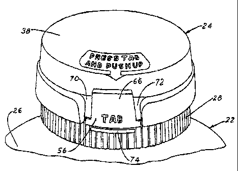
FIG.1 illustrates a child resistant closure and container package 20 in
accordance
with one presently preferred embodiment of the invention as comprising, a
container 22 and a
dispensing closure 24 secured to the container finish. Container 22 has a body
26 of flexible
resilient construction, preferably molded plastic construction, that may be
squeezed by a user to
dispense product through closure 24 from within the container. Referring to
FIGS.1-8, closure
24 includes a base 28 having a deck 30 and a peripheral skirt 32, Skirt 32 has
one or more
internal threads or beads 34 for securement over one or more external thztads
or beads on the
finish of container 22. A discharge or dispensing opening 36 is formed in deck
30, preferably
although not necessarily by an annular upwardly extending wall. (Directional
words such as
"upward" and "downward" are employed by way of description and not limitation
whit respect
to the upright orientation of the package and closure illustrated, for
example, in FIGS.1-2 and
4-6. Directional words such as 'radial," "axial" and "lateral" are employed by
way of description
and not limitation with respect to the central axis of the closure Skirt.) A
cover or lid 38 is
coupled to base 30 by a hinge 40 that extends beriveen lid 38 and base 28,
preferably but cot
necessarily between the periphery of lid 38 and the periphery of base 28.
Closure 24, including
base 28 and lid 38, preferably is of integrally molded plastic construction,
In the embodiment
of closure 24 illustrated in FIGS. 3- 8, an annular vvatl 42 extends ftom the
base wall 44 of lid
38 for plug-sealing ensageznent within dispensing opening 32 in the closed
position of lid 38
overlying deck 30 of base 28.
in the particular embodiment of closure 24 illustrated in FIGS. I-8, lid 38
has a
base wall 44 and a peripheral skirt 46. A bead 48 extends around the inside
surface of lid skirt
46 for sealing engagement with a radially outwardly facing Surface 50 otl base
28, which forms
an axially facing ledge 52 recessed beneath the upper surface of deck 30.
Where preferably is a
CA 02475706 2004-07-23
segmented bead 53 (FIGS. 5-6} on surface SU that cooperates with brad 48 on
lid 38 to hold the
lid closed by snap fit, with the axial edge of skirt 46 in abutment with ledge
52: Hiuga 40
preferably is of the type illusfirated in U.S. Fatent 6,041,477. hinge 40
alternatively, but less
preferably, may be of the type illustrated in LT.S. patents 4,638,916 and
5,489,035 noted above,
or any other suitable single-element or multiple-element type. An array of
internal teeth 41
preferably, although not necessarily, extends around the inside of skirt 36
adjacent to the free end
of the skirt for cooptrating with samilar teeth on the container to make the
closure non-
removable.
In accardanca with the embodiment of the invention illustrated in FIGS. I-$, a
Latch area 56 extends fram the periphery of lid 38 at a position diametrically
opposed to hinge 40.
Latcb arm 56 preferably is T shaped as viewed foam the radial direction (FIG.
6), having a center
leg 5$ coupled to and extending axially from the &ee edge of lid skirt 46 in
this embodiment,
and having a pair of tabs 60, 62 extending laterally from the free end of Leg
58. Tabs 60, 6a are
formed in the ilhasOrated embodiment at opposed ends of a bar 64 that extends
across the free end
of latch leg 5$ in a direction parallel to lid base wall 44. Tabs 60, 62
alternatively rxaay extend
from the side edges of leg 58, although use of a thickened bar 64 is preferred
to strengthen the
end of the latch arm. Latch arm 5b is flexibly and resiliently coupled to Lid
38 by reason of the
flexibility of lid shirt 46. An external bead 6b (FIGS. 3, 6 and 8) extends
across ieg 58 of latch
arm 56 adjacent to the edge of s8ort 46 in the preferred embodiments of the
invention fos
engagement by a user's thumb to open the closure, as will be described. ,As
best seen in FIG. 3,
Latch area 56, including leg 58 and bar 64, are arcuate as viewed from the
axial direction in this
embodiment of the invention, following the perlpherai contour of Iid 3 $. Tabs
60, 62 thus extend
circumfcrentially in this embodiment of the invention, in which base 28 and
lid 38 have circular
geometries. Base 2 $ and lid 3 $ may have other peripheral geometties, such as
oval or polygonal.
4
CA 02475706 2004-07-23
A rib 67 preferably extends axially along the inside surface of lid skirt 46
and latch arm leg 58,
circumferentially centered on arm S6 as best seen in FIG. 3, to strengthen
tile resilient coupling
of the latch arm to the Iid.
An axial passage 68 e~rtends along the outer surface of base skirt 32 at a
position
diametrically opposite hinge 40. Passage 6$ opens to deck 30 at its upper end,
and opens to the
radial outer surface of skirt 32. Passage 68 thus in essence comprises a
pocket or recess in the
outer surface of skirt 32 in this embodiment of the invention, which opens at
its upper end to
deck 30 of bast 28. As best seen in FIG. 3, passage b8 is arcuate as viewed
from the axial
direction, being contoured to receive latch arm 56 as will be described. A
pair of laterally spaced
ledges 70, 72 are provided at the laterally or circumferentially opposed edges
of passage 68,
Each Iedge 70, 72 has an associated tlat undersurface 71, 73, and a radialiy
outer surface that
slopes radially outwardly and axially downwardly in the orientation ofFIGS. ~1-
5. Passage 68
is open behind ledges 70, 72 to permit passage of latch arm 56, as will be
desexabed.
As lid 38 is pivoted about hinge 40 from the open position illustrated in
FIGS. 3-6
toward the closed position illustrated in F'iGS.1-2, tabs 60, 82 of latch arm
56 engage and slide
along the radially outwardly facing surfaces of ledges ?0, 72. These outer
surfaces, being
anguiated with respect to the axis of the closure skirt, cam the free end of
the latch arm radially
outwardly as the lid is closed, resiliently flexing latch arm 56 radially
outwardly with respect to
the body of lid 38. When tabs 60, 62 reach the lower ends of ledges 70, 72,
resiliency ofthe latch
arm and the lid connection snaps tabs 60, 62 radisIly inwardly beneath
undersuxfaces 71, 73 of
ledges 70, 72 to the fully closed position of the lid illustrated in FIGS.1
and 2. In this position,
leg 58 of latch artn 56 is received between Ledges 70, 72 in passage 68, and
tabs 60, 62 are
captured beneath ledges 70, 72. Lid 38 cannot be opened by simply pulling
upwardly on the lid
because tabs 60, 62 of latch arm 56 cooperate with ledges 70, 72 in passage 68
to lock the lid in
CA 02475706 2004-07-23
the closed position. A rib 74 preferably, although not necessarily, is
provided on the outer
surface of skirt 32 immediately beneath passage 68 to help prevent opening of
the closure by
insertion of a pry tool such as a screwdriver beneath latch arch 56.
When it is desired to open the lid, a user pushes radially inwardly against
the outer
surface of latch arm 56, which is exposed betvvecn ledges 70, 72 of passage
68. lndicia may be
provided on the closuxe to assist the user, as shorn in FIGS.1, 2 and 6.
Arrowhead indioia may
also be provided on the upper surface of lid 38, as shown in FIG. 1, to direct
a user to the latch
arm. When latch arm 56 is pushed radially inwardly into passage 68 to a
su$icient extent that
tabs 60, 62 clear undersurfaces 71, 73 of ledges 70, 72, the lid may be pushed
and pivoted
upwardly about hinge 40 to open the closure to dispense product, The back or
radially umer
surfaces of ledges 70, 72 are spaced from the back ar radially inner wall of
passage 68 to permit
free axial passage of Iatch arm tabs 60, 62. Release of the latch mechanism
and pivotal motion
of the lid in: this embodiment is a Continuous motion that facilitates use by
a person who
understands operation of the mechanism, but resists opening by a child. Eead
66 an the outer
surface of latch arm 56 facilitates upward pushing on the lid when latch arm
56 is depressed.
FIGS. 9-13 illustrate a child-resistant dispensing closure 76 in accordance
with
a modified embodiment of the invention. Elements in FIGS. 9-13 (and FIGS. 14-
16) that are
identified by reference numerals identical to those employed in FIGS,1-8
indicate identical or
similar components, and related components are designated with a letter
sufFix. . Closure base
ZO 28a in FIGS. 9-13 includes a raised rib 84 adjacent to hinge 40 to help
prevent entry of moisture
between baso 28a and lid 38a ins the closed position of the lid Dispensing
opening 36a in FIGS:
8-13 is fornned by an amnular wall having an angulated upper edge that helps
control dispensing
of Liquid product from within the package. A bead 53a (FIGS. 9 and 12) extends
part-way around
CA 02475706 2004-07-23
wall 50 of base 28 and cooperates with bead 48 on skirt 46 of lid 38a to snap
lid 38a in the closed
position over base 28a.
FIGrS. I4-16 illustrate a ono-piece child-resistant dispensing closure 90 in
accordance with another embodiment of the invention as including a base 28b
integrally molded
and connected to a lid 38b by means of a hinge 40. A latch arm 56b in this
embodiment is
resiliently coupled to skirt 32b of base 28b adjacent to the tiee edge of the
skirt 32b. Latch arm
56b again is T-shaped, having a leg 58b coupled to skirt 32b, and a pair of
laterally extending
tabs 60b, 62b formed by a bar 64b that extends across the free edge of leg
58b: A passage 68b
extends axially through the periphery of lid 38b at a position diametrically
opposite hinge 40.
Passage 68b has a pair of ledges 70b, 72b for engagement by tabs 60b, 62b of
latch arm 56b.
Passage 68b in lid 38b is radially outwardly enclosed by skirt 46b of lid 38b,
and is radially
inwardly enclosed by a wall 96 that limits inward movement of latch arm 56b.
The radially
outwardly directed surface of latch arm bar 64b iz~ the embodiment of FIGS, 14-
16 is disposed
at an angle to the axis of the closure base. Likewise, the axially facing
surfaces of ledges 70b,
I S 72b are disposed at an angle so as to cooperate with the angulated surface
of latch axon bar 64b
resiliently to cam the latch azm radially inwardly as lid 38b is closed over
base 28b. When tabs
60b, 62b clear ledges 70b, 72b, the resilient connection between latch arm ~6b
and skirt 32b
snaps tho latch arm radially outwardly so that tabs 60b, 62b overlie opposing
flat upper surfaces
on; ledges 70b, 72b to lock the lid in the closed position. To open the lid,
latoh arm S6b is pushed
radiaily inwardly until tabs 60b, 62b clear ledges 70b, 72b, at which point
lid 38b may be pivoted
from the closed position toward the open position for dispensing product from
within the
package. Base skirt 32b has an open pocket98 behind latch arm 56b to permit
such inward
flexing of the latch arm.
CA 02475706 2004-07-23
There have thus been disclosed a child-resistant claaure, and a child-
resistant
closure and container package that fully satisfy all of the objects and aims
previously set forth,
The closure has been disclosed in conjunction with three presently preferred
embodimeyzts
thereofw and a number of modifications and variarions have been discussed.
Other modifications
and variations will readily suggest themselves to pexsons of ordinary skill in
the art. The
invention is intended to embrace all such nnodi.fications and variations as
fall within the spirit and
broad scope of the appended claims.