Sélection de la langue

Search

Sommaire du brevet 2476644 

Énoncé de désistement de responsabilité concernant l'information provenant de tiers

Une partie des informations de ce site Web a été fournie par des sources externes. Le gouvernement du Canada n'assume aucune responsabilité concernant la précision, l'actualité ou la fiabilité des informations fournies par les sources externes. Les utilisateurs qui désirent employer cette information devraient consulter directement la source des informations. Le contenu fourni par les sources externes n'est pas assujetti aux exigences sur les langues officielles, la protection des renseignements personnels et l'accessibilité.

Disponibilité de l'Abrégé et des Revendications

L'apparition de différences dans le texte et l'image des Revendications et de l'Abrégé dépend du moment auquel le document est publié. Les textes des Revendications et de l'Abrégé sont affichés :

  • lorsque la demande peut être examinée par le public;
  • lorsque le brevet est émis (délivrance).
(12) Brevet: (11) CA 2476644
(54) Titre français: DIODE ELECTROLUMINESCENTE A INDICATEURS D'ETAT D'EMISSION LATERALE
(54) Titre anglais: LED SIGNAL WITH SIDE EMITTING STATUS INDICATORS
Statut: Accordé et délivré
Données bibliographiques
(51) Classification internationale des brevets (CIB):
  • F21S 08/00 (2006.01)
  • B61L 15/02 (2006.01)
  • F21V 01/00 (2006.01)
  • F21V 13/04 (2006.01)
(72) Inventeurs :
  • YOU, CHENHUA (Etats-Unis d'Amérique)
  • ADINOLFI, JOHN T. (Etats-Unis d'Amérique)
  • KULBERG, KURT A. (Etats-Unis d'Amérique)
  • PICCIOTTI, MICHAEL F. (Etats-Unis d'Amérique)
(73) Titulaires :
  • DIALIGHT CORPORATION
(71) Demandeurs :
  • DIALIGHT CORPORATION (Etats-Unis d'Amérique)
(74) Agent: ROBIC AGENCE PI S.E.C./ROBIC IP AGENCY LP
(74) Co-agent:
(45) Délivré: 2011-05-31
(22) Date de dépôt: 2004-08-05
(41) Mise à la disponibilité du public: 2005-03-29
Requête d'examen: 2009-07-31
Licence disponible: S.O.
Cédé au domaine public: S.O.
(25) Langue des documents déposés: Anglais

Traité de coopération en matière de brevets (PCT): Non

(30) Données de priorité de la demande:
Numéro de la demande Pays / territoire Date
10/671,505 (Etats-Unis d'Amérique) 2003-09-29

Abrégés

Abrégé français

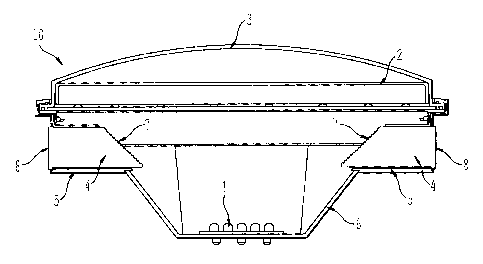
Dispositif d'éclairage comprenant des indicateurs d'état d'émission latérale qui donne une indication réelle quant à savoir si de la lumière est émise dans une direction principale. Le dispositif d'éclairage comprend une source lumineuse d'au moins une DEL, configurée de façon à émettre de la lumière dans une direction principale. La lumière émise par au moins une DEL traverse une lentille, qui peut également réfléchir une partie de la lumière émise par la DEL. Des éléments optiques de captage sont prévus pour capter une partie de la lumière émise et/ou la partie réfléchie de la même lumière provenant de la source lumineuse; ces éléments sont configurés de façon à transmettre la lumière captée et/ou réfléchie dans une direction autre que la direction principale, c'est-à-dire vers les indicateurs d'état d'émission latérale.


Abrégé anglais

A light device including side emitting status indicators that provide a true indication of whether light is being output in a primary output direction. The light device includes a light source of at least one LED configured to generate light in the primary output direction. The light generated by the at least one LEDs passes through a. lens device, that may also reflect a portion of the light generated from the at least one LED. Collection optics are provided to capture a portion of the generated light and/or the reflected portion of the light generated from the light source, and are configured to output the captured generated and/or reflected light in a direction other than the primary direction, i.e., in a direction for the side emitting status indicators.

Revendications

Note : Les revendications sont présentées dans la langue officielle dans laquelle elles ont été soumises.


WHAT IS CLAIMED IS:
1. A light device comprising:
(a) a light source comprising at least one light emitting diode (LED), and to
generate a majority of output light in a primary direction toward a front of
the light
device;
(b) a lens device through which the light generated from said light source
passes; and
(c) a collection optical unit to capture a portion of the light generated from
said light source and having a light output surface at a side of the light
device, and
to output the captured light in a direction other than the primary direction
toward the
side of the light device,
wherein said lens further reflects a portion of the light generated from said
light
source, and said collection optical unit further captures the reflected
portion of the
light generated from said light source, and outputs that captured reflected
light in
the direction other than the primary direction.
2. A light device according to claim 1, wherein said collection optical unit
(c)
comprises (c1) a light pipe with (c2) a collecting surface and (c3) the light
output
surface.
3. A light device according to claim 2, wherein the collecting surface (c2) of
the
light pipe comprises a plurality of prism elements.
4. A light device according to claim 2, further comprising:
(d) a sleeve configured to hold said light pipe, and
wherein an air gap is provided between said sleeve and said light pipe.
5. A light device according to claim 1, wherein said lens device (b) comprises
(b1) an inner lens and (b2) an outer lens.
6

6. A light device comprising:
(a) light source means for generating a majority of light in a primary
direction
toward a front of the light device;
(b) lens means through which the light generated from said light source
means passes; and
(c) collection means for capturing a portion of the light generated from said
light source means and having a light output surface at a side of the light
device,
and for outputting the captured light in a direction other than the primary
direction
toward the side of the light device;
wherein said lens means further reflects a portion of the light generated from
said
light source means, and said collection means further captures the reflected
portion
of the light generated from said light source means, and outputs that captured
reflected light in the direction other than the primary direction.
7. A light device according to claim 6, wherein said collection means (c)
comprises (c1) light pipe means with (c2) a collecting surface means and (c3)
the
light output surface.
8. A light device according to claim 7, wherein said collecting surface means
(c2) of the light pipe means comprises a plurality of prism means.
9. A light device according to claim 7, further comprising:
(d) holding means for holding said light pipe means with an air gap provided
between said holding means and said light pipe means.
10. A light device according to claim 6, wherein said lens means (b) comprises
(b1) an inner lens means and (b2) an outer lens means.
11. A light device comprising:
7

(a) a light source comprising at least one light emitting diode (LED), and to
generate light in a primary direction toward a front of the light device;
(b) a lens device through which the light generated from said light source
passes, and said lens device further reflecting a portion of the light
generated from
said light source; and
(c) a collection optical unit to capture the reflected portion of the light
generated from said light source and having a light output surface at a side
of the
light device, and to output the captured reflected light in a direction other
than the
primary direction toward the side of the light device.
12. A light device according to claim 11, wherein said collection optical unit
(c)
comprises (c1) a light pipe with (c2) a collecting surface and (c3) the light
output
surface.
13. A light device according to claim 12, wherein said collecting surface (c2)
of
the light pipe comprises a plurality of prism elements.
14. A light device according to claim 12, further comprising:
(d) a sleeve configured to hold said light pipe, and
wherein an air gap is provided between said sleeve and said light pipe.
15. A light device according to claim 11, wherein said lens device (b)
comprises
(b1) an inner lens and (b2) an outer lens.
16. A light device comprising:
(a) light source means for generating light in a primary direction toward a
front of the light device;
(b) lens means through which the light generated from said light source
means passes, and said lens means for further reflecting a portion of the
light
generated from said light source means; and
8

(c) collection means for capturing the reflected portion of the light
generated
from said light source means and having a light output surface at a side of
the light
device, and for outputting the captured reflected light in a direction other
than the
primary direction toward the side of the light device.
17. A light device according to claim 16, wherein said collection means (c)
comprises (c1) light pipe means with (c2) a collecting surface means and (c3)
the
light output surface.
18. A light device according to claim 17, wherein said collecting surface
means
(c2) of the light pipe means comprises a plurality of prism means.
19. A light device according to claim 17, further comprising:
(d) holding means for holding said light pipe means with an air gap provided
between said holding means and said light pipe means.
20. Alight device according to claim 16, wherein said lens means (b) comprises
(b1) an inner lens means and (b2) an outer lens means
9

Description

Note : Les descriptions sont présentées dans la langue officielle dans laquelle elles ont été soumises.


CA 02476644 2004-08-05
TITLE OF THE INVENTION
LED SIGNAL WITH SIDE EMITTING STATUS INDICATORS
BACKGROUND OF THE INVENTION
FIELD OF THE INVENTION
The present invention relates to a signal that includes side emitting status
indicators,
and in particular in which the signal includes an LED light source. Such a
signal can find
application, for example, as a railway indicating signal.
DISCUSSION OF THE BACKGROUND
A typical railway indicating signal utilizes an incandescent light bulb as a
light source.
Such a railway signal may be employed at a railway crossing. In that type of
signal the light
emitted from the incandescent light bulb passes through at least one red lens
to provide a
primary red signal to an oncoming motorist crossing the rail tracks. Also, two
additional light
ports, one on each side, maybe provided to provide objective evidence to a
train operator that
the light bulb is properly outputting light to the oncoming motorist. That is,
an operator on
the train can view light output from the additional light ports to confirm
that the light bulb in
the railway crossing light is properly operating. In that operation the light
provided to the
additional light ports is directly collected from the light source, i.e., the
incandescent light
bulb, by an optical window that utilizes prism features, and which refracts
light in the desired
direction.
SUMMARY OF THE INVENTION
One object of the present invention is to provide a novel signal, such as a
railway
indicating signal that utilizes an LED light source and that provides an
accurate side emitting
status indication.
The present inventors have recognized that as LED light sources become more
and
more available, LED light sources may be utilized in signal applications.
However, most
LEDs provide substantially directional light. In the context of a railway
signal, the light
-I-

CA 02476644 2009-09-22
output by an LED light source may pass through a lens or lenses providing
signals to
oncoming motorists. In such a case, since the LEDs provide substantially
directional light, in
a device such as a railway light with side emitting status indicators, there
is typically
insufficient light reaching the side emitting status indicators for a train
operator to view
because of the directional nature of the LEDs.
One way to solve that problem is to add additional LEDs to be directed to the
side
emitting status indicators. However, that approach does not provide a failsafe
indication to a
train operator since those additional LEDs may not always operate the same as
the primary
LEDs providing the light signal in a primary direction to an oncoming
motorist. That is, the
situation may arise that the LEDs providing a light signal in a primary
direction to an
oncoming motorist are not properly working, but different side facing LEDs
providing light in
a secondary direction to side emitting status indicators are properly working.
In that instance,
the train operator would not be given on accurate indication.
Accordingly, a more specific object of the present invention is to provide a
novel LED
signal with side emitting status indicators that provides a true indication of
the light provided
in a primary light output direction.
To achieve the above and other objects, the present invention in one aspect
sets forth a light device comprising:
(a) a light source comprising at least one light emitting diode (LED), and to
generate a majority of output light in a primary direction toward a front of
the light
device;
(b) a lens device through which the light generated from said light source
passes;
and
(c) a collection optical unit to capture a portion of the light generated from
said light
source and having a light output surface at a side of the light device, and to
output
the captured light in a direction other than the primary direction toward the
side of
the light device,
wherein said lens further reflects a portion of the light generated from said
light
2

CA 02476644 2009-09-22
source, and said collection optical unit further captures the reflected
portion of the
light generated from said light source, and outputs that captured reflected
light in
the direction other than the primary direction.
Another aspect of this invention sets forth a light device comprising:
(a) light source means for generating a majority of light in a primary
direction toward
a front of the light device;
(b) lens means through which the light generated from said light source means
passes; and
(c) collection means for capturing a portion of the light generated from said
light
source means and having a light output surface at a side of the light device,
and for
outputting the captured light in a direction other than the primary direction
toward
the side of the light device;
wherein said lens means further reflects a portion of the light generated from
said
light source means, and said collection means further captures the reflected
portion
of the light generated from said light source means, and outputs that captured
reflected light in the direction other than the primary direction.
Yet another aspect of this invention sets forth a light device comprising:
(a) a light source comprising at least one light emitting diode (LED), and to
generate light in a primary direction toward a front of the light device;
(b) a lens device through which the light generated from said light source
passes,
and said lens device further reflecting a portion of the light generated from
said light
source; and
(c) a collection optical unit to capture the reflected portion of the light
generated
from said light source and having a light output surface at a side of the
light device,
and to output the captured reflected light in a direction other than the
primary
direction toward the side of the light device.
Still another aspect of this invention sets forth a light device comprising:
(a) light source means for generating light in a primary direction toward a
front of
the light device;
2a

CA 02476644 2009-09-22
(b) lens means through which the light generated from said light source means
passes, and said lens means for further reflecting a portion of the light
generated
from said light source means; and
(c) collection means for capturing the reflected portion of the light
generated from
said light source means and having a light output surface at a side of the
light
device, and for outputting the captured reflected light in a direction other
than the
primary direction toward the side of the light device.
BRIEF DESCRIPTION OF THE DRAWINGS
A more complete appreciation of the present invention and many of the
attendant
advantages thereof will be readily obtained as the same becomes better
understood by
reference to the following detailed description when considered in connection
to the
accompanying drawings, wherein:
Fig. 1 shows a side view of the internal structure of the novel light device
of the
2b

CA 02476644 2004-08-05
present invention;
Fig. 2 shows a perspective view of the novel light device of the present
invention with
certain elements in an exploded view;
Fig. 3 shows a side view of the internal structure of the light device of the
present
invention that additionally indicates various light paths;
Fig. 4 shows a side internal view of specific collection optics for a side
emitting status
indicator in the novel light device of the present invention; and
Fig. 5 shows a perspective view of the collection optics for the side emitting
status
indicator of the present invention.
DESCRIPTION OF THE PREFERRED EMBODIMENTS
Referring now to the drawings, wherein like reference numerals identify
identical or
corresponding parts throughout the several views, and more particularly to
Figs. 1 and 2
thereof, views of a light device 10 of the present invention are shown. Fig. 1
shows an
internal view of the dialight device 10, and Fig. 2 shows the light device 10
from a
perspective view with certain elements exploded out.
As shown in Figs. 1 and 2, the light device 10 includes an overall housing 6
that
serves to house each of elements of the light device 10. The housing 6 can be
formed of any
suitable metal or plastic material. The light device 10 also includes a
plurality of light
emitting diode (LED) light sources 1. The number of LEDs 1 can vary based on
the specific
type of LEDs utilized.
The light device 10 also includes two lenses of an inner lens 2 and an outer
lens 3.
Light output from the LEDs 1 predominantly passes through the inner lens 2 and
the outer
lens 3 in a primary direction to provide a light indication signal. In the
context of a railway
indicator an oncoming motorist will view the light output from the LEDs 1 and
passing
through the inner lens 2 and the outer lens 3.
The light device 10 also includes additional side emitting status indicators
formed of
elements 4-8. The side emitting status indicators provide an indication signal
in a direction
other than the primary direction from which light from the LEDs is output.
Element 4 is a
light pipe that directs light collected at a collecting surface 7 to an exit
surface 8. The exit
surface 8 can be frosted to provide a diffused uniform illumination. The light
pipe 4 may be
-3-

CA 02476644 2004-08-05
made from plastics or glass or other optical materials. The light pipe 4 is
held in place by a
sleeve 5. In the context of a railway indicator, a train operator will be able
to view light
output from the exit surface 8 to have an indication whether the LEDs 1 are
properly
operating, and to thereby give an indication whether an oncoming motorist is
receiving a
proper indication signal.
The operation of the output of light from the LEDs 1 is shown in further
detail in Fig.
3, which shows the light device 10 with generated light beams,
With reference to Fig. 3, the LEDs 1 output primary light beams 11 to be
output in a
primary direction, i.e., the majority of the light beams 11 pass through the
inner lens 2 and the
outer lens 3 and then become viewable by, for example, an oncoming motorist.
While the
primary light beams 11 pass through the inner lens 2 and the outer lens 3, a
portion of the
primary light beams 11 are reflected at the surfaces of the inner lens 2 and
the outer lens 3
based on Fresnel losses, and those reflected light beams result in Fresnel
loss beams 12.
Those Fresnel loss beams 12 are collected by the collecting surfaces 7 of the
light pipes 4,
which are formed on each side of the light device 10, although Fig. 3 only
shows the
collection of the Fresnel loss beams 12 at one of the light pipes 4. The
collecting surfaces 7
of the light pipes 4 are formed with a plurality of prism elements 16 that
refract light into the
respective light pipes 4. The prisms elements can have any type of design such
that most
light reaching the sides of the light pipes 4 get total internal reflection.
The light collected at
the collecting surfaces 7 then travels through the respective light pipes 4 by
total internal
reflection, and then the collected light is output from the exit surfaces 8,
to thereby provide
output side emitting beams 14. The output side emitting beams 14 are visible
to, for
example, a train operator.
It is also the case that some light beams 13 output from the LEDs 1 will
directly
impinge on the collecting surfaces 7 of the light pipes 4 and also travel
through the light pipes
4 and result in the side emitting beams 14. In fact, it may be adequate for
only these light
beams 13 to be collected if those light beams 13 provide enough illumination
in the side
emitting beams 14. In that instance the reflected Fresnel loss beams 12 need
not be collected,
although in an embodiment both the Fresnel loss beams 12 and direct light
beams 13 are
collected.
Further details of the side emitting status indicator light collecting devices
of elements
-4-

CA 02476644 2004-08-05
4-8 is shown in Figs. 4 and 5. As shown in Fig. 4, the collecting surface 7 of
the light pipe 4
includes prism elements 16 integrally formed on the collecting surface 7.
Further, the sleeve
holds the light pipe 4 with a small air gap 15 therebetween. That is, a small
air gap 15 is
provided between the light pipe 4 and the sleeve 5, and that air gap 5 ensures
the total internal
reflection of the light beams passing through the light pipe 4.
Further, since the collecting surfaces 7 of the light pipe 4 are placed near
the edge of
the housing 6, as shown in Fig. 3, the main light beams 11 output by the LEDs
1 are not
interfered with by the collecting surfaces 7, and thereby no shadowing is
produced in the
main output light beams 11.
Such a structure of the light device 10 provides side emitting signal
indicators that
provide a true indication of the light output from the same LEDs 1 providing
light in a main
light output direction. Thereby an enhanced safety operation is achieved.
The light device 10 as described above has been mainly described in the
context of a
railway indicator signal. However, it is apparent to those of ordinary skill
in the art that the
light device 10 can be used in other contexts in which a side indication
whether a light signal
is being output in a primary direction is desirable.
Obviously, numerous additional modifications and variations of the present
invention
are possible in light of the above teachings. It is therefore to be understood
that within the
scope of the appended claims, the present invention may be practiced otherwise
than as
specifically described herein.
-5-

Dessin représentatif
Une figure unique qui représente un dessin illustrant l'invention.
États administratifs

2024-08-01 : Dans le cadre de la transition vers les Brevets de nouvelle génération (BNG), la base de données sur les brevets canadiens (BDBC) contient désormais un Historique d'événement plus détaillé, qui reproduit le Journal des événements de notre nouvelle solution interne.

Veuillez noter que les événements débutant par « Inactive : » se réfèrent à des événements qui ne sont plus utilisés dans notre nouvelle solution interne.

Pour une meilleure compréhension de l'état de la demande ou brevet qui figure sur cette page, la rubrique Mise en garde , et les descriptions de Brevet , Historique d'événement , Taxes périodiques et Historique des paiements devraient être consultées.

Historique d'événement

Description Date
Représentant commun nommé 2019-10-30
Requête pour le changement d'adresse ou de mode de correspondance reçue 2018-12-04
Accordé par délivrance 2011-05-31
Inactive : Page couverture publiée 2011-05-30
Inactive : Taxe finale reçue 2011-03-16
Préoctroi 2011-03-16
Un avis d'acceptation est envoyé 2010-10-08
Lettre envoyée 2010-10-08
Un avis d'acceptation est envoyé 2010-10-08
Inactive : Approuvée aux fins d'acceptation (AFA) 2010-10-05
Inactive : Correspondance - TME 2010-08-10
Modification reçue - modification volontaire 2009-09-22
Lettre envoyée 2009-09-09
Requête d'examen reçue 2009-07-31
Exigences pour une requête d'examen - jugée conforme 2009-07-31
Toutes les exigences pour l'examen - jugée conforme 2009-07-31
Lettre envoyée 2007-01-03
Inactive : Lettre officielle 2006-12-21
Exigences relatives à la nomination d'un agent - jugée conforme 2006-12-21
Exigences relatives à la révocation de la nomination d'un agent - jugée conforme 2006-12-21
Inactive : Lettre officielle 2006-12-21
Demande visant la révocation de la nomination d'un agent 2006-12-05
Demande visant la nomination d'un agent 2006-12-05
Inactive : Lettre officielle 2006-08-07
Lettre envoyée 2006-06-28
Inactive : Transfert individuel 2006-05-30
Inactive : CIB de MCD 2006-03-12
Lettre envoyée 2005-11-16
Exigences de prorogation de délai pour l'accomplissement d'un acte - jugée conforme 2005-11-16
Inactive : Prorogation de délai lié aux transferts 2005-11-04
Demande publiée (accessible au public) 2005-03-29
Inactive : Page couverture publiée 2005-03-28
Inactive : CIB attribuée 2004-11-03
Inactive : CIB attribuée 2004-10-18
Inactive : CIB en 1re position 2004-10-18
Inactive : Lettre de courtoisie - Preuve 2004-09-21
Inactive : Certificat de dépôt - Sans RE (Anglais) 2004-09-16
Demande reçue - nationale ordinaire 2004-09-16

Historique d'abandonnement

Il n'y a pas d'historique d'abandonnement

Taxes périodiques

Le dernier paiement a été reçu le 2010-07-16

Avis : Si le paiement en totalité n'a pas été reçu au plus tard à la date indiquée, une taxe supplémentaire peut être imposée, soit une des taxes suivantes :

  • taxe de rétablissement ;
  • taxe pour paiement en souffrance ; ou
  • taxe additionnelle pour le renversement d'une péremption réputée.

Les taxes sur les brevets sont ajustées au 1er janvier de chaque année. Les montants ci-dessus sont les montants actuels s'ils sont reçus au plus tard le 31 décembre de l'année en cours.
Veuillez vous référer à la page web des taxes sur les brevets de l'OPIC pour voir tous les montants actuels des taxes.

Titulaires au dossier

Les titulaires actuels et antérieures au dossier sont affichés en ordre alphabétique.

Titulaires actuels au dossier
DIALIGHT CORPORATION
Titulaires antérieures au dossier
CHENHUA YOU
JOHN T. ADINOLFI
KURT A. KULBERG
MICHAEL F. PICCIOTTI
Les propriétaires antérieurs qui ne figurent pas dans la liste des « Propriétaires au dossier » apparaîtront dans d'autres documents au dossier.
Documents

Pour visionner les fichiers sélectionnés, entrer le code reCAPTCHA :


Pour visualiser une image, cliquer sur un lien dans la colonne description du document. Pour télécharger l'image (les images), cliquer l'une ou plusieurs cases à cocher dans la première colonne et ensuite cliquer sur le bouton "Télécharger sélection en format PDF (archive Zip)" ou le bouton "Télécharger sélection (en un fichier PDF fusionné)".

Liste des documents de brevet publiés et non publiés sur la BDBC .

Si vous avez des difficultés à accéder au contenu, veuillez communiquer avec le Centre de services à la clientèle au 1-866-997-1936, ou envoyer un courriel au Centre de service à la clientèle de l'OPIC.


Description du
Document 
Date
(aaaa-mm-jj) 
Nombre de pages   Taille de l'image (Ko) 
Abrégé 2004-08-04 1 22
Description 2004-08-04 5 293
Revendications 2004-08-04 3 141
Dessins 2004-08-04 2 60
Dessin représentatif 2005-02-28 1 12
Description 2009-09-21 7 342
Revendications 2009-09-21 4 129
Certificat de dépôt (anglais) 2004-09-15 1 168
Demande de preuve ou de transfert manquant 2005-08-07 1 101
Rappel de taxe de maintien due 2006-04-05 1 112
Courtoisie - Certificat d'enregistrement (document(s) connexe(s)) 2006-06-27 1 105
Rappel - requête d'examen 2009-04-06 1 122
Accusé de réception de la requête d'examen 2009-09-08 1 175
Avis du commissaire - Demande jugée acceptable 2010-10-07 1 163
Correspondance 2004-09-15 1 26
Correspondance 2005-11-03 2 48
Correspondance 2005-11-15 1 16
Correspondance 2006-08-06 1 25
Taxes 2006-07-18 1 35
Correspondance 2006-12-04 3 67
Correspondance 2006-12-20 1 14
Correspondance 2006-12-20 1 17
Correspondance 2007-01-02 1 14
Taxes 2006-07-18 1 34
Correspondance 2006-12-05 2 41
Correspondance 2010-08-09 1 47
Correspondance 2010-10-07 1 77
Correspondance 2011-03-15 2 55