Sélection de la langue

Search

Sommaire du brevet 2477798 

Énoncé de désistement de responsabilité concernant l'information provenant de tiers

Une partie des informations de ce site Web a été fournie par des sources externes. Le gouvernement du Canada n'assume aucune responsabilité concernant la précision, l'actualité ou la fiabilité des informations fournies par les sources externes. Les utilisateurs qui désirent employer cette information devraient consulter directement la source des informations. Le contenu fourni par les sources externes n'est pas assujetti aux exigences sur les langues officielles, la protection des renseignements personnels et l'accessibilité.

Disponibilité de l'Abrégé et des Revendications

L'apparition de différences dans le texte et l'image des Revendications et de l'Abrégé dépend du moment auquel le document est publié. Les textes des Revendications et de l'Abrégé sont affichés :

  • lorsque la demande peut être examinée par le public;
  • lorsque le brevet est émis (délivrance).
(12) Demande de brevet: (11) CA 2477798
(54) Titre français: DEBITMETRE MASSIQUE DE CORIOLIS DE MESURE DE CONCENTRATION
(54) Titre anglais: CORIOLIS MASS FLOW METER FOR MEASURING CONCENTRATION
Statut: Réputée abandonnée et au-delà du délai pour le rétablissement - en attente de la réponse à l’avis de communication rejetée
Données bibliographiques
(51) Classification internationale des brevets (CIB):
  • G01F 1/84 (2006.01)
  • G01N 9/00 (2006.01)
(72) Inventeurs :
  • MATT, CHRISTIAN (Suisse)
(73) Titulaires :
  • ENDRESS + HAUSER FLOWTEC AG
(71) Demandeurs :
  • ENDRESS + HAUSER FLOWTEC AG (Suisse)
(74) Agent: SMART & BIGGAR LP
(74) Co-agent:
(45) Délivré:
(86) Date de dépôt PCT: 2003-02-26
(87) Mise à la disponibilité du public: 2003-09-18
Requête d'examen: 2004-08-31
Licence disponible: S.O.
Cédé au domaine public: S.O.
(25) Langue des documents déposés: Anglais

Traité de coopération en matière de brevets (PCT): Oui
(86) Numéro de la demande PCT: PCT/EP2003/001957
(87) Numéro de publication internationale PCT: WO 2003076879
(85) Entrée nationale: 2004-08-31

(30) Données de priorité de la demande:
Numéro de la demande Pays / territoire Date
102 10 061.6 (Allemagne) 2002-03-08

Abrégés

Abrégé français

L'invention concerne un débitmètre massique de Coriolis permettant de déterminer des concentrations, pour lequel une fonction quelconque de concentration est stockée en mémoire dans une unité d'évaluation de concentration (210). L'utilisateur a ainsi la possibilité de produire une valeur de concentration adaptée à l'utilisation voulue, pour une température et une masse volumique prédéterminées.


Abrégé anglais


The invention relates to a coriolis mass flowmeter for determining a
concentration, wherein a concentration function is stored in a concentration
evaluation unit (210). As a result, the user can produce a concentration value
correlating to the use thereof at a predetermined temperature and thickness of
the medium.

Revendications

Note : Les revendications sont présentées dans la langue officielle dans laquelle elles ont été soumises.


5
CLAIMS
1. Coriolis mass flow meter for determining concentration, comprising a
digital signal
processor (DSP), which determines from the sensor signals and the temperature
signals of a transducer the density of the flowing fluid, and a concentration
evaluating
unit (210) connected thereafter, in which a concentration curve is stored.
2. Coriolis mass flow meter as claimed in claim 1, characterized in that the
concentration curve is stored in the form of a two-dimensional polynomial.
3. Coriolis mass flow meter as claimed in claim 2, characterized in that the
degree of the
density polynomial is 4 and the degree of the temperature polynomial is 3.

Description

Note : Les descriptions sont présentées dans la langue officielle dans laquelle elles ont été soumises.

CA 02477798 2004-08-31
FL0158-US
CORIOLIS MASS FLOW METER FOR MEASURING CONCENTRATION
The invention relates to a Coriolis mass flow meter for measuring
concentration.
Coriolis mass flow meters are used in many cases for determining mass flow of
a fluid in
a section of a pipeline. In this, the fluid flows through at least one
oscillating measuring
tube. In most Coriolis mass flow meters, one oscillation exciter and two
oscillation
sensors are arranged on the measuring tube. Measuring tube and fluid form,
together, an
oscillatable system, which is normally excited to its resonance frequency. The
resonance
frequency depends on, among other things, the material and the dimensions of
the
measuring tube. It varies, additionally, with the density of the flowing
fluid. In some
cases, the measuring tube is not excited to the resonance frequency, but,
instead, to a
neighboring frequency. The two oscillation sensors register the oscillatory
motion of the
measuring tube at two locations spaced from one another in the direction of
flow and
convert the oscillatory movements of the measuring tube to sensor signals.
Both sensor
signals have the same frequency as the oscillatory movement of the measuring
tube, but
they are shifted in phase relative to one another. The phase shift between
these two
sensor signals is a measure of the mass flow rate.
The sensor signals are evaluated in a signal processing unit and converted
into a signal
proportional to the mass flow rate. Besides the mass flow rate, other
properties of the
fluid can also be determined, for example its density. For this purpose, the
frequency of
the oscillatory motion of the measuring tube is evaluated and, if need be, the
temperature
of the flowing fluid is determined.
Such a Coriolis mass flow meter is known from the commonly-owned patent
application
DE 100 45 537.
Often in industrial processes, the concentration of a solution is a measured
quantity of
interest. This is true for mass- and volume-concentrations, as well as for
various industry-
specific concentration specifications, such as °Oechsle in wine-
production or °Plato in
beer brewing. A basic ingredient for the measurement of concentration in most
cases is
the density of the fluid. Correspondingly, various density functions, for
example °Brix,
°Plato, °Balling, °API, are already implemented in the
Coriolis mass flow meters Promass
63 and Promass 83 of the firm Endress + Hauser~.
Various concentration measures are, however, not defined unequivocally in the
literature.
Different users apply different definitions, which then lead to different
concentration
values.
In the case of conventional Coriolis mass flow meters, the output of different
concentration values is only conditionally possible.
1

CA 02477798 2004-08-31
2 FL0158-US
It is an object of the invention to provide a Coriolis mass flow meter for
concentration
measurement, which is simple and economical to manufacture.
This object is achieved by a Coriolis mass flow meter for concentration
measurement as
defined in claim 1.
Advantageous further developments of the invention are given in the dependent
claims.
An essential idea of the invention is the providing in the Coriolis mass flow
meter for
measuring concentration a unit, in which a predeterminable concentration curve
is stored.
There follows a more detailed explanation of the invention on the basis of an
example of
an embodiment, as illustrated in the drawings, which show as follows:
Fig. 1 a schematic drawing of the transducer of a Coriolis mass flow meter;
and
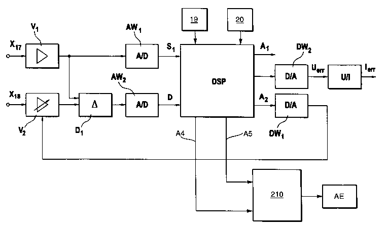
Fig. 2 a block diagram of a signal processing unit for a Coriolis mass flow
meter having a
concentration determining unit.
Fig. 1 is a schematic drawing of a transducer 1 for a Coriolis mass flow
meter. The
transducer 1 is arranged in a pipeline, which is not shown in further detail.
A fluid F flows
in the pipeline. The mass flow rate of the fluid is one of the parameters of
interest. The
connection with the pipeline is by way of the two flanges 2, 3.
The transducer 1 includes a single, straight measuring tube 4, which is
secured at its inlet
end at the flange 2 by an end-plate 13 and at its outlet end at flange 3 by an
end-plate 14.
The flanges 2, 3 and the end-plates are secured on or in a support tube 15.
For causing the measuring tube to oscillate, an oscillation exciter 16 is
arranged at the
middle of the measuring tube 4 between the two end-plates 13, 14. The
oscillation
exciter 16 can be, for example, an electromagnetic drive composed of a
permanent
magnet 161 and a coil 162. The coil 162 is secured to the tube 15 and the
permanent
magnet to the measuring tube 4. The amplitude and the frequency of the bending
oscillation of the measuring tube 4, which occurs in the plane of the drawing,
are
controlled by the electrical current flowing in the coil 162.
Coriolis forces arise in the plane of the drawing, when a fluid F flows
through the
measuring tube 4. A result of these forces is that all points of the measuring
tube 4 no
longer oscillate in phase.
The oscillatory motion of the measuring tube 4 is registered with the help of
two oscillation
sensors 17, 18, which are arranged likewise on the support tube, about
symmetrically on
either side of the oscillation exciter 16. The oscillation sensors 17, 18 can
be, for
2

CA 02477798 2004-08-31
3 Ft_0158-US
example, electromagnetic converters, which are constructed similarly to the
oscillation
exciter 16.
The two permanent magnets 171, 181 thereof are secured to the measuring tube 4
and
the two coils 172, 182 are secured to the support tube 15. The motion of the
measuring
tube 4 causes the magnets 171, 181 to induce voltages in the associated coils
171, 181,
and these voltages are tapped as analog sensor signals X17, respectively X~B.
Two temperature sensors 20, 19 serve for registering the temperature of the
fluid.
Temperature sensor 19 is located on end-plate 13 and temperature sensor 20 is
on
support tube 15.
Transducer 1 is connected to a digital signal processing unit DSP. The signal
processing
unit DSP delivers at its outputs the measurements mass flow rate, density and
temperature of the flowing fluid F.
Fig. 2 is a block diagram of the signal processing unit associated with the
transducer 1.
Among other things, it evaluates the sensor signals X,~, X~s and it regulates
the oscillation
excitations of the measuring tube 4. The two sensor signals X~~ and X~8 are
fed,
respectively, to a first amplifier V~ and a second amplifier V2. The
amplification of the
amplifier V2 is variable via an adjustable amplification factor.
The amplifier V~ is connected to an AID converter AWE and to a difference
stage D~ in
parallel therewith. The amplifier V2 is connected to a second input of the
difference stage
D,. The output of the difference stage D~ is connected to a second AlD
converter AW2.
The two outputs of the A/D converters AWE and AW2 provide, respectively, the
sensor
signal S~ and the difference signal D, both in digital form. Both outputs are
connected to
respective inputs of the digital signal processing unit DSP.
The two temperature sensors 19 and 20 are likewise connected to respective
inputs of
the signal processing unit DSP.
The signal processing unit delivers, in known manner, on plural outputs A~,
A4, A5 the
values of the mass flow rate, the density and the temperature, respectively,
of the fluid F.
Additionally, the signal processing unit DSP controls the exciter current,
which drives the
oscillation excitation of the measuring tube 4 and the amplification factor VF
of the
amplifier V2.
The signal processing unit is additionally connected to a concentration
determining unit
210. In the concentration determining unit 210, density and temperature of the
fluid are
evaluated. The concentration determining unit 210 is connected to a display
unit AE for
displaying the desired concentration value. Besides presenting the
concentration value in
the display unit AE, a transmitting of the concentration value to a
superordinated

CA 02477798 2004-08-31
4 FL0158-US
evaluating unit (not shown in further detail) is also possible.
The concentration determining unit 210 stores a concentration curve C as a
function of
density and temperature of the fluid. Input of the current density value and
the current
temperature of the fluid enables easy determination of the desired
concentration.
One possibility for storing the concentration curve is to store the
corresponding
polynomial coefFcients. The polynomial coefficients can be easily determined
by
providing concentration values for particular density and temperature values
and
conducting a corresponding polynomial approximation.
In the simplest case, this involves a two-dimensional polynomial.
M Z
c(p,~)=~ap'+ ~b~'
i=0 i=1
The polynomial degree of the density polynomial is preferably M=4, the
polynomial
degree of the temperature polynomial Z=3.
By entering various concentration values, a user can produce a concentration
specification tuned to one's application.
4

Dessin représentatif
Une figure unique qui représente un dessin illustrant l'invention.
États administratifs

2024-08-01 : Dans le cadre de la transition vers les Brevets de nouvelle génération (BNG), la base de données sur les brevets canadiens (BDBC) contient désormais un Historique d'événement plus détaillé, qui reproduit le Journal des événements de notre nouvelle solution interne.

Veuillez noter que les événements débutant par « Inactive : » se réfèrent à des événements qui ne sont plus utilisés dans notre nouvelle solution interne.

Pour une meilleure compréhension de l'état de la demande ou brevet qui figure sur cette page, la rubrique Mise en garde , et les descriptions de Brevet , Historique d'événement , Taxes périodiques et Historique des paiements devraient être consultées.

Historique d'événement

Description Date
Inactive : Morte - Aucune rép. dem. par.30(2) Règles 2010-10-25
Demande non rétablie avant l'échéance 2010-10-25
Réputée abandonnée - omission de répondre à un avis sur les taxes pour le maintien en état 2010-02-26
Inactive : Abandon. - Aucune rép dem par.30(2) Règles 2009-10-23
Inactive : Dem. de l'examinateur par.30(2) Règles 2009-04-23
Inactive : CIB de MCD 2006-03-12
Lettre envoyée 2004-11-05
Inactive : Page couverture publiée 2004-11-02
Lettre envoyée 2004-10-29
Inactive : Acc. récept. de l'entrée phase nat. - RE 2004-10-29
Demande reçue - PCT 2004-09-27
Inactive : Transfert individuel 2004-09-13
Exigences pour l'entrée dans la phase nationale - jugée conforme 2004-08-31
Exigences pour une requête d'examen - jugée conforme 2004-08-31
Toutes les exigences pour l'examen - jugée conforme 2004-08-31
Demande publiée (accessible au public) 2003-09-18

Historique d'abandonnement

Date d'abandonnement Raison Date de rétablissement
2010-02-26

Taxes périodiques

Le dernier paiement a été reçu le 2009-01-22

Avis : Si le paiement en totalité n'a pas été reçu au plus tard à la date indiquée, une taxe supplémentaire peut être imposée, soit une des taxes suivantes :

  • taxe de rétablissement ;
  • taxe pour paiement en souffrance ; ou
  • taxe additionnelle pour le renversement d'une péremption réputée.

Veuillez vous référer à la page web des taxes sur les brevets de l'OPIC pour voir tous les montants actuels des taxes.

Historique des taxes

Type de taxes Anniversaire Échéance Date payée
Requête d'examen - générale 2004-08-31
Taxe nationale de base - générale 2004-08-31
Enregistrement d'un document 2004-09-13
TM (demande, 2e anniv.) - générale 02 2005-02-28 2005-01-19
TM (demande, 3e anniv.) - générale 03 2006-02-27 2006-01-23
TM (demande, 4e anniv.) - générale 04 2007-02-26 2007-01-23
TM (demande, 5e anniv.) - générale 05 2008-02-26 2008-01-23
TM (demande, 6e anniv.) - générale 06 2009-02-26 2009-01-22
Titulaires au dossier

Les titulaires actuels et antérieures au dossier sont affichés en ordre alphabétique.

Titulaires actuels au dossier
ENDRESS + HAUSER FLOWTEC AG
Titulaires antérieures au dossier
CHRISTIAN MATT
Les propriétaires antérieurs qui ne figurent pas dans la liste des « Propriétaires au dossier » apparaîtront dans d'autres documents au dossier.
Documents

Pour visionner les fichiers sélectionnés, entrer le code reCAPTCHA :


Pour visualiser une image, cliquer sur un lien dans la colonne description du document. Pour télécharger l'image (les images), cliquer l'une ou plusieurs cases à cocher dans la première colonne et ensuite cliquer sur le bouton "Télécharger sélection en format PDF (archive Zip)" ou le bouton "Télécharger sélection (en un fichier PDF fusionné)".

Liste des documents de brevet publiés et non publiés sur la BDBC .

Si vous avez des difficultés à accéder au contenu, veuillez communiquer avec le Centre de services à la clientèle au 1-866-997-1936, ou envoyer un courriel au Centre de service à la clientèle de l'OPIC.


Description du
Document 
Date
(aaaa-mm-jj) 
Nombre de pages   Taille de l'image (Ko) 
Description 2004-08-31 4 217
Abrégé 2004-08-31 1 10
Dessins 2004-08-31 2 42
Revendications 2004-08-31 1 19
Dessin représentatif 2004-08-31 1 11
Page couverture 2004-11-02 1 32
Accusé de réception de la requête d'examen 2004-10-29 1 177
Rappel de taxe de maintien due 2004-11-01 1 110
Avis d'entree dans la phase nationale 2004-10-29 1 201
Courtoisie - Certificat d'enregistrement (document(s) connexe(s)) 2004-11-05 1 106
Courtoisie - Lettre d'abandon (R30(2)) 2010-01-18 1 164
Courtoisie - Lettre d'abandon (taxe de maintien en état) 2010-04-26 1 171
PCT 2004-08-31 5 146