Note : Les descriptions sont présentées dans la langue officielle dans laquelle elles ont été soumises.
CA 02477988 2004-09-02
WO 03/074257 PCT/CA03/00312
_ 'j _
Apparatus for the manufacture of a disposable electrophoresis
cassette and method thereof
BACKGROUND OF THE INVENTION
(a) Field of the Invention
The present invention is related to an apparatus for the
manufacture of a disposable electrophoresis cassette and to the
manufacture process thereof.
(b) Description of Prior Art
Electrophoresis is a well known separation technique that
requires the application of electrical current at both poles of a cassette or
plate to force samples through an electrophoretic medium that acts as a
molecular sieve. The application of a difference of potential between the
upper section and the lower section of the cassette assumes the creation
of two areas sealed from each other: Because current is transmitted via
two separate buffer reservoirs, it is necessary to apply a pressure or force
on the cassette so that the seals properly operate. !t is therefore
imperative that the whole system, including the cassette, possess some
rigidity.
Conventional electrophoresis cassettes are made of two glass
plates spaced apart with plastic spacers or tongues (often in plastic, ABS,
rubber or other non-conductive material) to create a space therebetween
while ensuring that the sides of the assembly are properly sealed.
Importantly, the spacers must not conduct electrical current. The assembly
is generally maintained together with clamps, and it is often necessary to
reinforce the seals with hot agar or grease (like petroleum jelly). When the
gel is cast into the cassette, a comb element is introduced at one end of
the assembly (usually define as the Top of the cassette) to create one or
more reservoirs or wells thereafter wherein the samples) will be received
later. The shape of the comb may comprise various numbers and sizes of
reservoirs, depending on the application required and the size of the
cassette. For example, a preparation gel necessitate less reservoirs, while
an analytical gel will require more reservoirs and the width thereof will
depend on the resolution desired.
CA 02477988 2004-09-02
WO 03/074257 PCT/CA03/00312
-2-
However, such assemblies have several drawbacks and
limitations. The assembling operation requires dexterity and is a time-
consuming operation, because it is done manually. The plates are
conventionally made of glass, and thus must be handled with care.
Further, they must be carefully cleaned to obtain good results. Finally,
manipulation of acrylamide gel, a commonly used electrophoretic medium,
represents a long-term danger for the health of operators since such gel is
highly toxic.
More recently, to simplify the assembling work of operators and
reduce poisoning and manipulation hazards, pre-cast cassettes already
containing the gel have been made available commercially. The cassettes
comprise an acrylamide gel, and a comb .is provided at one extremity
thereof. However, the cost of these cassettes is prohibitive, and demolding
thereof, for visualization of the results, is a delicate and complicated
procedure. In addition, the comb is produced by injection molding, and is
used to form the wells or reservoirs in the gel. They generally represent an
important part of the total cost of the cassette.
To be economically feasible and capable of supporting, without
substantial bending, the mechanical forces applied thereon, cassettes
containing pre-cast electrophoresis medium, must be rigid .enough and
made of a material economically sound and preferably recyclable, such as
for example thermoplastic materials like polymethylmethacrylate (PMMA).
However, conventionally, in order to be sufficiently rigid, the plates must be
relatively thick. Two obvious problems therefore become apparent: a) the
amount of thermoplastic material required is significant, thus increasing the
cost, which is not suitable for a disposable device; and b) maintaining the
gel at an appropriate operating temperature is complicated, because the
thick walls of the thermoplastic material act as a dielectric material.
Thicker plastic walls also affect the diffusion of the heat generated during
the electrophoretic process, creating temperature gradients within the
electrophoresis medium, and non-uniform migration of the samples
analyzed.
Conventional processes for filling the cassettes are generally
standard, irrespective of the electrophoretic medium. Typically, a gel
CA 02477988 2004-09-02
WO 03/074257 PCT/CA03/00312
-3-
comprising a mixture of acrylamide and bis-acrylamide, a buffer like tris-
borate ethylenediamine (EDTA), tris-acetate-EDTA, tris-glycine, tricine, and
a polymerization initiator are injected or cast into the cassette. Some of
these products are neurotoxic and/or irritant, and must therefore be
handled with extreme care. A laboratory pipette or a pump can be used to
fill the cassette from the top with the liquid medium. Once the cassette is
filled, a comb closes the top of the cassette. The comb has a design such
that it contains one or more teeth forming reservoirs in the gel wherein the
sample will be placed later. After polymerization of the medium, the comb
is removed, as well as a separator present in the lower portion of the
cassette. The cassette is then placed in an electrophoresis apparatus
wherein the lower and upper portions of the gel will be in contact with two
independent buffer solutions relating to the electrodes. The samples are
then introduced in the reservoirs, and current is applied to separate the
various components of each sample. After completion of the separation,
the medium is removed from the cassette for further processing, i.e.,
coloration, photograph and analysis.
Again, such system and procedure have various major
drawbacks and limitations. As stated above, manual filling of the cassette
requires great care and dexterity, not to mention exposure of the operator
to toxic chemicals. Further, undesirable bubbles often form during filling,
and installation of the comb after filling may also create bubbles at the
bottom of the teeth. Such air bubbles must be avoided at all times, since
they interfere significantly with the samples migrating in the polymerized
gel during the electrophoresis procedure.
Pre-cast gels have been marketed recently, but have not been
able to overcome other problems mentioned above for cassettes
containing the same, such as prohibitive costs. One of the main reason is
that the cassettes are obtained by injection molding, which is a costly and
relatively slow process because of the significant amount of plastic
required for injection, the cost of the plastic material itself, and the time
necessary to allow complete cooling of the cassette thus obtained. In
addition, because the cassettes are made of a thermoplastic material, gel
polymerization is greatly. affected and slowed down because the polymer
absorbs free radicals generated by the chain reaction of the polymerization
CA 02477988 2004-09-02
WO 03/074257 PCT/CA03/00312
-4-
or free oxygen molecules which affect the polymerization efficiency. As a
result, the polymerized electrophoretic medium does not "stick" do the
cassette inner surfaces. An expensive coating layer or overlay must
therefore be applied on the thermoplastic material surfaces to minimize this
problem and ensure proper polymerization quality and speed.
The electrophoresis operation necessitates the application of a
voltage across the, gel that generates heat that must be somehow
dissipated. During the heat dissipation process, if the temperature of the
gel is not uniform, it causes distortion in the separated protein or
polynueleic acid bands shown as a "smiling effect" or loss of resolution
(thicker bands). Such heat is therefore a critical problem because it limits
the rate at which gels can be run. Increasing temperatures reduces the
resistance and increases current at a given voltage. Although the net
effect is a shorter run, excessive temperature can lead to undesirable band
broadening. It is therefore preferable to run at a higher voltage and a
constant lower temperature.
It would be highly desirable to be provided with a cassette having
thin plastic walls using a minimal amount of plastic, being adapted to any
existing electrophoresis boxes and systems, being low-cost to produce and
being easy to fill.
SUMMARY OF THE INVENTION
One aim of the present invention is to provide a mold that allows
easy preparation of a disposable electrophoresis cassette within the
specification.
A further aim of the present invention is to provide a relatively
simple and efficient manufacturing process for the production of a
disposable electrophoresis cassette.
A still further aim of the present invention is to provide a mold
and a process for industrial production in a~ large volume and at lower
manufacturing cost of electrophoresis cassettes.
Another aim of the present invention is to provide a gel filing
method allowing easy preparation of a disposable electrophoresis cassette.
CA 02477988 2004-09-02
WO 03/074257 PCT/CA03/00312
-5-
Another aim of the present invention is to provide a comb for a
disposable electrophoresis cassette° that prevents gel polymerization
between the comb and the cassette walls during utilization.
In accordance with the present invention there is provided a
mold for the manufacture of an electrophoresis cassette, the mold
comprising a body having a cassette molding part formed on one face
thereof, the cassette molding part being surrounded by a peripheral sheet
engaging portion extending in a plane located at a different elevation than
the cassette molding part to provide for substantially uniform stretching of
the sheet on the cassette molding part.
In accordance with the present invention, there is also provided a
molding method for the manufacture of an electrophoresis cassette
comprising the steps of:
a) heating a thermoforming material applied on a
thermoforming mold suitable for the manufacture of an electrophoresis
cassette;
b) applying a pressure on the material to closely maintain the
material on the mold;
c) stretching the material to obtain an uniformly distributed
material surface;
d) cooling the material to form a molded material surface with
cooling parameters adapted to provide an uniformly distributed material
surface; and
e) providing holes in a peripheral portion of the
electrophoresis cassette facing a peripheral portion comprising reservoirs
entries.
In accordance with the present invention, there .is further
provided a method for filing an electrophoresis medium into an
electrophoresis cassette comprising the steps of:
a) sealing at least one aperture of the cassette;
b) injecting the electrophoresis medium into the cassette;
CA 02477988 2004-09-02
WO 03/074257 PCT/CA03/00312
-6-
c) applying a pressure onto the cassette, in order to generate a
flat and even electrophoresis separation area in the electrophoresis
medium.
In accordance with the present invention, there is still further
provided a comb for an electrophoresis cassette adapted to be removably
inserted into the cassette comprising at least one tooth having protrusion
provided thereto for preventing the electrophoresis medium gel attachment
to the comb and/or for preventing acrylamide polymerization.
BRIEF DESCRIPTION OF THE DRAWINGS
Fig.1 is a perspective exploded view of a cassette and the
corresponding support plate in accordance with an embodiment of the
present invention;
Figs.2A-2D are a partial perspective view of a comb developed in
accordance with an embodiment of the present invention;
Figs. 3A and 3B are partial front and rear perspective views of a
hybrid comb developed in accordance with an embodiment of the present
invention.
Fig.4 is a partial view of the support plate developed for
supporting the present cassette;
Fig. 5 is a perspective view of the mold used to prepare the
cassette of Fig. 1;
Figs. 6A and 6B are cross-sectional views of the mold used to
prepare the cassette of Fig. 1; and
Fig, 7 is a side view of another embodiment of the mold of the
present invention.
DETAILED DESCRIPTION OF THE INVENTION
The invention relates to the field of electrophoresis, and more
particularly to a cassette suitable therefor. It is to be assumed that the gel
used as the electrophoretic medium is preferably an acrylamide (or
polyacrylamide) gel, whether cross-linked or not. However, other
conventional and well known electrophoretic media such as agarose gel or
starch gel, can be used. Polyacrylamide gel is particularly preferred
CA 02477988 2004-09-02
WO 03/074257 PCT/CA03/00312
-7-
because it is transparent, electrically neutral, and can be made in various
pore sizes. Other co-monomers well known in the field include N,N'-
methylenebisacrylamide, N,N-bisacrylylcystamine, N,N'-(1,2-
dihydroxyethylene)bisacrylamide, N,N'-diallyl-tartardiamide, and the like.
The cassette of the present invention is a cassette defined by a
reservoir, made of plastic by a,process allowing the formation of very thin
surfaces, preferably thermoforming or "thin wall" molding, a cover made of
a material suitable for the manufacture of an electrophoresis cassette and
providing sufficient rigidity to have a structure allowing the cassette to
stay
flat and linear. A male mold type is used to provide more precision and
allow molding pieces with smaller-narrower details while female molding
provide pieces with larger details. The cassette also comprises a comb,
made of molded plastic, designed to inject an electrophoretic medium
and/or to mold wells into the cast gel in order to have cavities to receive
the
sample to be analyzed, a fixing structure to maintain the cover and
reservoir together and finally a support plate to receive the cassette and to
adapt it into an electrophoresis box for usage. The fixing structure is
preferably a liquid glue applied by lithography or silk-screen or a double-
face tape, but could be any fixing structure that is not using heat for fixing
and is therefore preventing the deformation of the cassette.
Because several technical difficulties occurred with traditional
thermoforming method for the manufacture of the cassette, a
thermoforming mold was prepared that allow homogenous plastic
stretching and well-controlled process.
This mold requires a unique approach of construction.
Stretching plastic is not a homogeneous and well-controlled process. To
obtain the optimal results in the molding of the cassette of the present
invention, the following are needed:
i) Male or female types of mold are selected based on the precision
to obtain. Female type is used to produce pieces with larger details,
while male molding provide more precision and allow molding pieces
with smaller-narrower details;
ii) A groove is preferably carved around the mold to control the
stretch of the plastic; .
CA 02477988 2004-09-02
WO 03/074257 PCT/CA03/00312
_g_
iii) Preferably, the mold is slightly elevated from the groove rear
surface in order to stretch even more the plastic in the formed
depression, which contribute to the symmetrical stretching of the
plastic forming the cassette;
iv) A relative symmetry in the placing of the position stretch points
around the molding cavities help to not misbalance the stretching;
v) The use of vacuum holes in a sufficient quantity to generate an
effective contact between the material surface and the groove rear
surfiace of the mold and therefore a flat molding;
vi) Providing a chilling sufficient to cool rapidly the produced item,
avoiding therein any deformation of the material surface;
vii) In the thermoforming machine and process, the heating of the
plastic can be done with different types, size and strength of heating
elements that will change the melting evenness of the plastic sheet
prior thermoforming and allow a control of the plastic stretching
during molding;
viii) Cooling elements can be introduced into the mold to affect and
control the cooling evenness of the plastic during and after
thermoforming process and prevent tension, twisting and
deformation in the plastic due to wrong cooling or radiating heat;
ix) The residual heat coming from the surrounding plastic around the
molded area is sufficient to radiate again into the molded part and to
create bending, twisting or tensions, all deformation which will affect
the molded part. It is preferable to minimize the radiating heat re-
distribution during the molding process via die-cutting the molded
part to detach it from the heated plastic roll. During this process,
attachment points are usually left to allow manipulation of the
molded part and easy removal from the machine. In the present
invention, the minimum number and the smallest size of attachment
points are preferred.
The drawings provided herewith are for the sole purpose of
illustrating preferred embodiments of the invention, and shall not be
considered as limiting the scope thereof.
CA 02477988 2004-09-02
WO 03/074257 PCT/CA03/00312
_g_
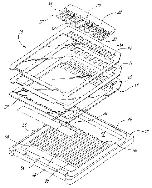
Referring to drawings, Fig. 1 illustrates a cassetfie assembly 10
and a support 12 therefor. Cassette 10 comprises a top plate 14 and a
reservoir plate 16 each of a substantially square shape and having their
four edges seated, either with an adhesive layer 11 inserted therebetween,
or with the help of any other compatible sealing means such as glue,
ultrasonic welding, tape etc. The structure of layer 11 is complementary
with that of both plates 14 and 16.
Plates 14 .and 16 are preferably made of a chemically and
electrically inert material and at least on of plates 14 and 16 is having the
desired degree of rigidity to support and protect the 'gel during casting
thereof, as well as shipping and handling operations. A thermoplastic
"thermoformable" material is most preferred because the plates can be
produced commercially via sheet thermoforming, which is quick, reliable
and relatively cheap. Preferred thermoplastic materials suitable for the
purposes of the invention include any electrically and chemically inert
thermoplastic material that can be easily and economically thermoformed.
Most preferred examples are polystyrene, high density polyethylene
(HDPE), low density polyethylene (LDPE), linear low density polyethylene
(LLDPE), polyethylene terephtalate (PET), glycol-modified PET,
polyethylene naphthalate, polyvinyl chloride (PVC), polyvinylidene chloride
(PVDC), polycarbonate, PMMA" Barex, Topas, polyvinylacetate (PVA),
ethylene vinylacetate (EVA), polypropylene, polyesters, cellulose acetates,
polyamides such as nylonT"", and copolymers thereof. Preferably, both
plates 14 and 16 are made of the same material for compatibility purposes.
In addition, at least reservoir plate 16 should be transparent, but it is
preferred that both plates 14 and 16 be transparent.
They could however be also made of a material suitable for "thin
wall" injection molding as TPX, which has a lower density of about 0.9 that
making it more fluid and allowing a more efficient injection of the plastic in
the cavity to form a 20/1000 or more plastic wall: Any suitable materials for
injection having a small density while heated are other desirable materials
for the manufacture of the cassette.
Reservoir plate 16 comprises a series of reservoirs 18 for
receiving a corresponding series of teeth 20 of comb 22. Top plate 14 has
CA 02477988 2004-09-02
WO 03/074257 PCT/CA03/00312
- 10-
a complementary structure, i.e., a series of openings 24, that allow the
passage therethrough of the plurality of teeth 20 for engagement into
reservoirs 18. Reservoir plate 16 further comprises a series of slots 26
aligned with the series of reservoirs 18, and of substantially the same
width. During filling, shipping and handling operations, these slots are
sealed with a removable sealing strip 28 that will be removed before
placing cassette 10 in the electrophoresis device. In an alternate
embodiment, it has been found that the series of slots 26 can be replaced
with slots having a smaller width but being present in a greater number, i.e,
preferably twice the number of slots 26, with the same end result.
Comb 22 comprises an aperture or inlet 30 extending
therethrough substantially perpendicularly to its longitudinal section, and
aligned with a tooth 32, the latter comprising a longitudinal recess 34
shown in phantom lines in Figs. 2A-2D and serving as an outlet. After
engagement of teeth 20 into the series of reservoirs 18, an electrophoretic
medium is injected into cassette 10 through aperture 30 and recess 34, as
indicated by arrow 36. The flow of electrophoretic medium inside cassette
is also indicated by arrows 31 and 33. To ensure complete and proper
filling of cassette 10, as well as minimizing air bubbles, a slight excess of
electrophoretic medium must be injected. Such excess is discharged out
of cassette 10 through a longitudinal recess 38 provided in each tooth 18.
The flow of discharge is indicated by arrow 44. Recess 38 is located on
the side of a tooth 20 that is opposite to the side of tooth 32 comprising
recess 34. Each tooth 20 further comprises a pair of grooves 40 and 42,
the depth of which being much smaller than that of recess 38, and
arranged to form a V. The purpose of these grooves is mainly to facilitate
gel separation from comb 22 upon removal thereof after completion of
polymerization of the electrophoretic medium, although they may also be
useful for discharge of excess of gel. Grooves 40 and 42 allow a clean
separation of comb 22 from the gel, thus leaving a lower surface of
reservoir 18 containing the medium substantially similar and even in each
reservoir 18.
Figs. 3A and 3B illustrate a preferred embodiment of the comb
22 of the present invention. Comb 22 comprises an aperture or inlet 30
extending therethrough substantially perpendicularly to its longitudinal
CA 02477988 2004-09-02
WO 03/074257 PCT/CA03/00312
-11-
section. After engagement of teeth 20 into the series of reservoirs 18, an
electrophoretic medium is injected into cassette 10 through aperture 30. To
ensure complete and proper filling of cassette 10, as well as minimizing air
bubbles, a slight excess of electrophoretic medium must be injected. Each
tooth 20 further comprises a protrusion 104 made of relatively soft and
elastic material (such as rubber, urethane silicone, Chemraz, Viton, Buna-
N, Aegis, Kalrez, Teflon, EPDM, Aflas, Neoprene, Fluorosilicone,
Polyurethane and Mil-spec) and having the characteristic to both occupy
and pressured the reservoir 18 and prevent liquid introduction between the
teeth 20 and the cassette 10. When the protrusion 104 is made of a
material known as an acrylamide polymerization inhibitor like silicone or
urethane, it prevent acrylamide polymerization when the cassette 10 is
filled with an electrophoresis medium.
During the electrophoretic medium casting process, the medium
is poured into cassette 10 through opening 30 of comb 22, and allowed to
solidify. Preferably, the cassette is held in a manner such that plates 14
and 16 are kept substantially parallel to facilitate the filling of the
cassette.
Plates 14 and 16 can be kept substantially parallel by, for example,
applying a tension on each side thereof to stretch its position, or a "non-
sticky" glue is applied on the external surface of the plates, so that the
latter can be removably "stuck" during injection of the electrophoretic
medium therebetween. Alternately, a vacuum can be applied both outside
and inside the cassette, i.e., inside for drawing the gel inside the cassette,
and outside for maintaining the plates substantially parallel. A combination
of vacuum outside and positive pressure inside the cassette may also be
used. The polymerization process begins after an excess of medium has
poured out of each recess 38, confirming complete filling of cassette 10.
This method therefore substantially eliminates air bubbles from cassette
10. Once polymerization is complete, cassette 10 is stored appropriately in
a conventional manner.
Comb 22 is preferably removed only minutes prior to the use of
the cassette, or immediately after complete polymerization of the gel, prior
to storage, if the reservoirs 18 are well preserved from dehydration. At that
point, it is slowly pulled out of the cassette, and each reservoir 18 is
CA 02477988 2004-09-02
WO 03/074257 PCT/CA03/00312
-12-
thereafter filled with an appropriate volume of a sample to be
electrophoresed.
It is well known that in operation, the temperature of the
electrophoresis gel increases. It is also well known that the temperature
will be higher towards the middle of the cassette than on the sides thereof.
As a result, the migration front of the products to be separated is altered,
and erroneous interpretation might occur. A novel support plate has
therefore been developed to overcome these problems, as well as for
providing a proper profile maintenance, i.e., sufficient rigidity of the thin
walls of the cassette, and facilitating installation of the cassette into an
operational position in a conventional electrophoresis apparatus.
Support plate 12 comprises a frame 46 adapted to receive
therein cassette 10, and comprising a surface 48 with a plurality of
longitudinal recesses 50, which can be of any shape and size. Openings
52 and 54 are cut within the plate to define a free space substantially
corresponding in size to reservoir 18 and slots 26. When cassette 10 is
placed onto support 12, it lies directly onto ridges 56 of plate 12, thus
forming a series of channels between recesses 50 and a surface of
cassette 10 for circulation of the buffer solution therein (flow indicated by
arrows 51 ), and thus helping dispersing heat generated within the cassette.
As illustrated, each recess 50 is preferably aligned with a reservoir 18 and
a slot 26, to ensure that the temperature of the migrating product and the
gel is substantially the same, whether the reservoir is near the side or the
middle of the cassette. It has however been found that such alignment is
not mandatory. The critical element is that some buffer solution is allowed
to circulate between the support plate and the cassette to "extract" heat
from the latter. Support 12 can be made of any suitably rigid material, but
is preferably made of a heat conducting material, so that heat is also
extracted from ridges 56 that are in direct contact with the surface of
cassette 10 lying thereon, and dispersed within the structure of the
support. Cassette 10 can be maintained in place in plate 12 with the help
of a couple of retainer plates 58.
With respect to the problem of interference of the polymerization
process caused by the thermoplastic material of the cassette, it has been
CA 02477988 2004-09-02
WO 03/074257 PCT/CA03/00312
- 13-
found that by combining a powerful initiator generating more free radicals
with an appropriate "sticking" agent in the gel composition, there is no
longer a need to apply a costly protective layer over the thermoplastic
surfaces. Examples of such initiators include ammonium persulfate and
N,N,N,N-tetramethylethylenediamine (TEMED); 4-
dimethylaminopropionitrile; 1-hydroxycyclohexyl phenyl ketone; 2,2-
diethoxy-acetophenone; 2,2-dimethoxy-2-phenylacetophenone; 2',4'-
dimethoxy-acetophenone; 2-hydroxy-2-methyl-1-propiophenone; 2-
hydroxy-2-methyl-1-phenylpropan-1-one, and mixtures thereof. These
strong initiators allow a substantially complete polymerization of the gel.
However, the resulting polymerized gel does not stick to the plastic
surface, which is critical, particularly in view of the fact that the cassette
structure is relatively flexible. Detachment or unsticking of the polymerized
electrophoretic medium from the cassette inner surfaces may lead to the
introduction of undesirable air bubbles between the plastic surface and the
gel, and may also cause irregularities in the medium structure, thus
severely impairing the efficiency of the cassette. Surprisingly, it has been
found that by adding to the gel composition a small amount of an adhesive
compound is sufficient to allow the gel to adequately stick onto the plastic
surface. The adhesive compound preferably corresponds to that used for
coating the inner surfaces of currently available thermoplastic cassettes for
the same purpose. However, the costs associated with the processing and
coating of such a layer on the inner surfaces of the cassette are significant.
On the other hand, in the present invention, all one has to do is to add a
sufficienfi amount of the said adhesive compound into the gel composition
to be injected into the cassette to achieve the same result. Not only is the
procedure more simple, but the amount of adhesive compound required is
smaller. Suitable adhesive compounds include polysilazanes or tetra-
substituted silicon derivatives. The substituents can be the same or
different, and include a straight or branched alkyl, alkoxy, ketone, ester or
amide each comprising from 1 to 8 carbon atoms, or an amino, halogen,
cyano or hydroxy. Preferred adhesives are alkyl alkoxy silane derivatives.
Most preferred adhesives include Silane A-174,
methacryloxytrimethoxysilylpropane, 3-(trimethoxysilyl)propyl methacrylate,
CA 02477988 2004-09-02
WO 03/074257 PCT/CA03/00312
-14-
3-methacryloxypropyltrimethoxysilane, MEMO, DYNASYLAN MEMO, and
y-methacryloxypropyltrimethoxysilane.
The thickness of plates 14 and 16 should be sufficient to be rigid
enough for operation in an electrophoresis system. For economical
purposes, it has been found that it is not necessary to exceed a thickness
of about 40/1000, preferably 20/1000.
'Fig. 5 is referred to a mold 80 comprising a frame 82, a vacuum
outlet 84, a cooling inlet 86 and a cooling outlet 88. The frame 82
comprises a cavity 90 having a rear surface 92 perforated with a plurality of
vacuum holes 94. Relatively centered to the rear surface 92 are a plurality
of individual cassette molds 96 (either male or female molds), which are
slightly elevated from the rear surface 92 to ensure a maximal stretch of
the plastic during thermoforming. Each individual cassette mold 96
comprises pins 98 to assure a symmetrical stretching of the plastic during
thermoforming. The individual cassette molds 96 each have a
substantially square shape body defining an aperture 100 for the formation
of a reservoir surface and a series of reservoir molding slots 102 above the
aperture 100.
Fig. 6A is referred to the mold 80 comprising tubing 106 for
conducting cooling or heating fluid through the mold 80. Fig. 6B represents
another embodiment of the present invention, where the tubing 106 are
installed in different zones of the mold 80, provided herein a different
heating or cooling rate. In another embodiment of the present invention,
heating elements differs for different zones in the mold 80, allowing a
different heating to be performed for the different zones of the mold 80.
Fig. 7 is referred to another embodiment of the mold 80
comprising an upper part 114 and a lower part 116, the lower part 19 6
comprising a base 118 having a body 120 attached thereto. The body 120
having provided thereto heating/cooling elements 106, a vacuum chamber
108 to provide a sheet of material to be properly maintain in the mold 80
during molding, a cassette molding part 92 surrounded by a peripheral
sheet engaging portion 110 and an engagement member 122. The upper
part 114 is applied on the lower part 116 having the engagement member
122 adapting into a recess 124 and the upper part 114 providing a
CA 02477988 2004-09-02
WO 03/074257 PCT/CA03/00312
-15-
pressure to maintain a molded sheet material in a desired configuration
while cooling. A pressure chamber 112 can provided in the upper part 114
to apply a pressure by compressed air on the molded sheet material in
addition of the pressure from the upper part 114.
The electrophoresis cassette is composed of two distinct parts, a
flat cover which is a non-thermoform thin PVC plate (it can also be
replaced by any other material or thickness providing sufficient rigidity to
the cassette) and a thermoformed thin piece. Both parts are assembled
together preferably via a gluing process.
Production of the cover (Silk-screen printinu)
The complete cassette is very sensitive to tension. The plastic
could cause these tensions or the way the cassette being assembled. For
instance, heating the plastic can release (desirable) or creates
(undesirable) tensions depending under which conditions it is heated.
Handling the plastic can also cause undesirable tensions. In order to
manufacture cassette a reproducible way an approach which minimize
such tensions was developed.
Print one layer of paint on flatten PVC sheets
The ink application has only decorative purposes.
Allow complete drying
The glue being a critical step in the product production, the paint
needs to be properly cured to allow proper application and attachment of
the glue. Commercial glues will be cured either via UV light exposition or
air drying.
Print one layer of acrylic based glue on painted zone
The most common way to receive PVC is in large rolls. Under
such format, the plastic keeps a memory of a curved shape following its
position in the roll. This round shape is likely to create undesirable
tensions in the final assembly. In order to prevent tension problems in the
final cassette, there is a need to use flatten PVC sheets (flatten via slight
heating and maintaining in a compressed area). Glue was also found the
most appropriate approach to assemble the cassette. Since thin walls are
CA 02477988 2004-09-02
WO 03/074257 PCT/CA03/00312
-16-
used to constitute the electrophoresis cassette, the little amount of plastic
present provide too little resistance and high thermal conductivity into the
plastic, which can generate tension (such as curving and bending of the
cassette), so classic welding approaches to attach these plastic pieces
together are not acceptable and had to be replaced by gluing. Gluing also
present an advantage to make the cassettes easy to open after
electrophoresis. The simplest way to apply the glue is through silk-screen
printing (screen printing, silk screening engraving) or even application of
double face tape.
The choice of glue is critical since several glues are likely to
affect the electrophoresis pattern when the gel is in.;use. Acrylic based
glue with minimal amounts of organic or inorganic solvent are preferred.
Such types of glue are commercially available are need to be either cured
using UV light exposition, air drying or direct.
Die-cut wells' holes and contour
Die cutting of the plastic piece is required to allow final assembly.
Normal and classic blade based die can be used. Water knifes of laser
cutter can also be used for this process.
Production of the reservoir
Preferably, the production of the reservoir is performed using
thermoforming. However, it is also contemplate to use a "thin wall"
injection technique to arrive to another embodiment of the present
invention.
Due to the usage of thin plastic, this step requires a proper
control of the molding process in order to prevent any tension, curving,
bending or deformation in the thermoformed part. The clarity,
transparency of the plastic must also be preserved through the process.
Installation of the material sheet on production mold and
thermoforming machine
Preferably 20/1000 thick plastic in a roll form or in sheet can be
used as based material for production. Thinner or thicker plastic can also
be used, but better results based on structural qualities and plastic waste is
obtained with such material.
CA 02477988 2004-09-02
WO 03/074257 PCT/CA03/00312
-17-
Produce thermoformed pieces
The thermoforming process can be done from sheets of plastic,
one sheet at a time, however, this process is preferably made in
continuous, a plastic roll passing through a heating system, followed by a
pressing and thermoforming station, followed by a die-cutting station, which
can be also done simultaneously with the thermoforming, followed by a
thermoformed pieces removing station.
With all thermoforming, dry sheet is heated to a controlled
softening temperature, stretched to conform to the mold contours and
cooled to the temperature at which the part becomes rigid and maintains
the desired. shape. The formed part is trimmed to eliminate edges and
fabricated into the final configuration.
Thermoforming can be performed on any thermoforming
machine; however, key parameters must be respected. For instance,
heating is preferably made by radiating heat (keep transparency).
Standard heating system is preferably used; however, more controllable
results could be used using different heating elements with different
heating strength. Once property heated the plastic sheet is displaced over
the thermoforming area to be shaped. Process using vacuum forming
(using a negative pressure between the sheet and the mold), or pressure
forming (using a positive pressure on the opposite side of the sheet and a
negative pressure between the sheet and the mold can be used with
success. Due to the high specification and flatness, evenness
requirements, a rapid and strong cooling is preferably used. The mold
base is constituted of tubing and channels to allow coolant liquids like
water or other cooling material. In the actual case, we force cooling by
using pre-chilled water to pass through the mold. The channels in the
mold can be designed to offer different level and speed of cooling in order
to control the stretch and cooling performance in specific and well define
areas of the mold. In the preferred approach, the cooled piece is
immediately die-cut to be separated from the rest of the hot plastic sheet
and then to prevent heat radiation to return into the molded part as it
leaves the thermoforming area.
CA 02477988 2004-09-02
WO 03/074257 PCT/CA03/00312
Produce by strips of 3 cassettes to use full width of plastic roll
Since it is imperative to keep the molded part away from any
deformations (due to manipulation or heat radiation), the minimal residual
plastic is left around the molded part. The maximum of a standard size
plastic roll is used; the thermoforming area will then occupy most of the
width of the plastic roll, minimizing lost and warm plastic that could radiate
back.
Die-cut cassette bottom holes
In order to allow contact between the polyacrylamide gel and the
buffer and the electrode, holes need to be made at the bottom of the
cassette. A punch is preferably used to perform the holes in order to
minimize mechanical tension due to pressure apply by knifes or blades on
the plastic sheets.
Assemble both part under press
The thermoformed 3 cavity strips are cleaned and installed on a
jig. The silk-screen produced cover sheet with its 3 glued area matching
the 3 cassette thermoformed cavities area also positioned on the jig to
allow binding via pressure.
Die-cut cassette out of assembled piece
The assembled strips are then die-cut using a standard blade
based die to liberate 2 cassettes ready to be filled.
On top of producing the cassettes, filling them with the gel
solution is also requiring an inventive manufacturing process. The
electrophoresis cassettes being made of thin and relatively soft plastic
sheets, they need to be positioned in a form (or exoskeleton) to shape their
final configuration until the gel is entirely polymerized. Filling can be done
in the exoskeleton chamber with or without its comb and the gel poured in
the cassette via the top opening or via a hole in the comb until the exact
quantity or level is attained. After complete polymerization, the cassette is
removed from the exoskeleton to be bagged or used.
As an expandable small to large-scale production method, a
preferred filling process is:
CA 02477988 2004-09-02
WO 03/074257 PCT/CA03/00312
_19_
The bottom holes of the cassette are blocked by a plastic or
rubber tape (like electric tape) to prevent liquid acrylamide leakage.
The cassette is maintained in a vertical position in a fixture of
some sort. Such fixture should not affect the plastic flexibility in front or
back sides of the gel area.
A known amount (example 6.4 ml for an 8x8x1 cm cassette
reservoir) of polyacrylamide solution is poured in the reservoir area.
The comb (plastic or hybrid) is positioned on the top of the gel in
the well cavity area. At this stage, due to flexibility of the plastic sheets,
the
liquid acrylamide generate a pressure on the cassette walls having them
behave as a balloon. The level of solution is much lower than the comb
position. Such level could not allow proper electrophoretic separation.
The filled cassette is delicately moved into exoskeleton. This
fixture is then delicately closed to press in sandwich the cassette between
the two solid walls of the fixture and give to the soft cassette the shape it
should have in order to generate an adequate flat and even electrophoretic
separation area in the polyacrylamide gel.
The gels can be polymerized with this method either by chemical
stimulation using ammonium persulfate and TEMED, or via UV
polymerization using initiators like 1-hydroxycyclohexyl phenyl ketone, 2,2-
Diethoxyacetophenone, 2,2 Dimethoxy-2-phenylacetophenone, 2',4'-
Dimethoxyacetophenone, 2-Hydroxy-2-methyl-1-propiophenone, 2-
Hydroxy-2-methyl-1-phenyl-propan-1-one.
Gradient gels (example 4% to 20% acrylamide and other
recipes) as well as continuous gels can be produced using this approach.
While the invention has been described in connection with
specific embodiments thereof, it will be understood that it is capable of
further modifications and this application is intended to cover any varia-
tions, uses, or adaptations of the invention following, in general, the
principles of the invention and including such departures from the present
disclosure as come within known or customary practice within the art to
which the invention pertains and as may be applied to the essential
CA 02477988 2004-09-02
WO 03/074257 PCT/CA03/00312
-20-
features hereinbefore set forth, and as follows in the scope of the
appended claims.