Note : Les descriptions sont présentées dans la langue officielle dans laquelle elles ont été soumises.
CA 02478192 2004-08-19
DROP CEILING AIR FLOV~ PRODUCER
FIELD OF THE INVENTION
The invention relates generally to air flow producers for
reducing temperature gradients in a room, and, more specifically, to air flow
producers adapted for installation in drop ceilings.
BACKGROUND OF THE INVENTION
It is well known that warm air forced into a room or derived
from radiators tends to rise toward the ceiling of a room while cooler air
tends
to accumulate near the floor. This produces a temperature gradient that
exposes individuals to colder room air during winter months and increases
heat loss through ceilings and roofs. A corresponding problem arises during
summer months. Individuals may experience a room as being hot because
cool air discharged from air conditioning units tends to settle to the floor.
Thermostat setting are often changed to obtain more heat or more cool air. In
either case, the net result is increased energy consumption and higher cooling
and heating costs.
It is also well known that ceiling fans can reduce room
temperature gradients and consequently heating costs. The air flows from a
ceiling fan tend, however, to spread rapidly, reducing the ability to affect
temperature differentials. It is now common practice to use an air flow
producer that produces a vertical column of air if significant temperature
gradients and attendant heating and air conditioning costs are to be reduced.
-1-
CA 02478192 2004-08-19
A particular producer configuration is used for drop ceilings.
Such ceilings have a framework, usually an assembly of T-bars and hangers
that suspend the T-bars from a supradjacent ceiling. The framework defines
rectangular openings with standard dimensions in which ceiling panels are
seated. Building codes often specify that air flow producers used in drop
ceilings are not to draw air from the plenum above. In such applications, an
air flow producer must both receive and discharge air from below the drop
ceiling. Such devices are identified in this specification as "drop ceiling
air
flow producers" or with comparable terms.
Prior art drop ceiling producers have commonly used a
rectangular housing that conforms to dimensions of a seating opening and the
rectangular seating structure surrounding the opening. Apart from seating the
producer, this arrangement closes the opening against immediate intake of
plenum air. Intake and discharge zones are defined in a flow grill overlaying
the open bottom of the housing. A fan with a rotary blade assembly is
mounted centrally within the housing, and a circular band surrounds the blade
assembly to separate intake and discharge air flows. The band forces air flows
from the fan through a circular discharge zone centered in the flow grill.
Peripheral sections of the grill serve as an intake zone to supply air to the
fan.
To avoid custom fabrication, the flow producer will usually be manufactured
with a standard square housing whose sides conform to standard spacing
between drop ceiling rails, usually 24 inches. During installation, the rails
of
-2-
CA 02478192 2004-08-19
the drop ceiling are adjusted to define a square opening and seating structure
that accommodate the square producer.
Such air flow producers have been promoted as being very
efficient for production of high-volume, columnar air flows. However, the
inventors have discovered that an alternative configuration tends to be more
efficient and can be adapted to fit into standard rectangular openings in a
drop
ceiling framework.
SUMMARY OF THE INVENTION
In general terms, this specification offers solutions to two
principal problems. First, it provides a circular drop ceiling air flow
producer
that can exceed the performance of certain commercially available prior art
square units. Second, it provides a convenient approach to installing a
non-rectangular drop ceiling air flow producer (such as a circular producer)
in
a rectangular opening in a drop ceiling without drawing air from the plenum
above.
In one aspect, the invention provides a drop ceiling air flow
producer adapted to mount in a rectangular seating opening of a drop ceiling
framework. The air flow producer comprises a housing with a
circular-cylindrical side wall, a closed top and an open bottom. A flow grill
overlays the open bottom of the housing, and a fan is supported from within
the housing. The fan has a rotary blade assembly centered about a central
vertical axis of the housing and operable to discharge air through the grill.
A
_3_
CA 02478192 2004-08-19
circular flow-separating ring or band is centered about the vertical axis and
surrounds the blade assembly. The band defines a generally circular air
discharge zone centered in the grill, and an annular air intake zone radially
or
horizontally outward of the discharge zone. The producer includes a flange
with a generally rectangular periphery. The flange extends horizontally
outward relative to the side wall of the housing, and conforms in shape to the
opening and seating structure. This prevents immediate intake of air from the
plenum above the drop ceiling.
The circular configuration of the producer lends itself to higher
air flow rates. It has also been discovered that the circular flow-separating
band should be positioned differently than in prior art rectangular producers
to
maximize performance. In particular, performance of the prior art rectangular
producers improves as the band is positioned in the upper half of the housing.
In the circular housing configuration of the invention, flows rates improve
markedly when the band is located in the lower half of the housing, preferably
within 1 or 2 inches inches from the open bottom and the top of the flow
grill.
Other aspects of the invention will be apparent from a
description below of a preferred embodiment and will be more specifically
defined in the appended claims. A number of matters of interpretation should,
however, be noted. The term "circular-cylindrical" and comparable terms
should be understood as comprising a cylindrical periphery with a circular
cross-section. 'The term "rectangular" should be understood as encompassing
-4-
CA 02478192 2004-08-19
"square." Use of length measurements with decimal places should not be
interpreted as requiring exacting precision. For example, "23.75 inches" as
used to identify the diameter of a housing should be viewed essentially as
shorthand for "23 and three--quarter inches" and not as a direction to machine
components to two decimal places. Also, no distinction should be drawn
between measurements such as "5.0 inches" and "5 inches" as no such
distinction is intended. The invention does not require exacting measurement
of components.
DESCRIPTION OF THE DRAWINGS
The invention will be better understood with reference to
drawings in which:
Fig. 1 is a partial cross-section in a vertical plane of a circular
air flow producer mounted on a drop ceiling with intalke and discharge air
flows indicated with arrows;
Fig. 2 a plan view of the air flow producer from below with a
air flow grill removed;
Fig. 3 is a fragmented perspective view further detailing the
mounting of the air flow producer to ceiling structures;
fig. 4 is an exploded perspective view of the air flow producer;
and,
Fig. 5-7 are graphs comparing air flows produced by the
circular air flow producer and a conventional square air flow producer as a
-5-
CA 02478192 2004-08-19
function of the size and position of a flow dividing band in each unit.
DESCRIPTION OF PREFERRED EMBODIMENT
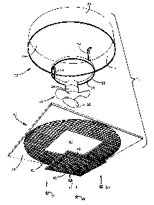
Reference is made to figs. 1-3 which illustrate an air flow
producer 10 adapted. to produce a high-volume columnar air flow. The
producer 10 is specifically adapted for installation in a drop ceiling 12. As
most apparent in figs. 1 and 3, the drop ceiling 12 comprises a framework of
horizontal T bars 14 and vertical hooks 16 (most apparent in fig. 3) that
support the T bars 14 from the supradjacent ceiling 18. In this instance, the
T-bar framework is adjusted in a conventional manner to define a square
opening, generally indicated with reference numeral 20 in fig. 3, and square
seating structure surrounding the opening 20. The producer 10 seats in the
opening 20, and draws air from and discharges air below the drop ceiling 12.
The air flow producer 10 has a generally circular housing 22
constructed of sheet metal. The housing 22 has a circular-cylindrical side
wall
24 centered about a vertical axis 26 (shown in fig. 1), a closed top 28 and an
open bottom 30. The side wall 24 has a diameter of about 23.75 inches and a
height of about 5 inches. The housing 22 contains a fan 32 with an electric
motor 34 and a rotary blade assembly 36 (most apparent in figs. 1 and 2). The
motor 34 is suspended centrally from the top 28 of the housing 22, and the
blade assembly 36 rotates about the vertical axis 26, producing a downward air
flow. A circular band 38 separates air flows to and from the blade assembly
36.
-6-
CA 02478192 2004-08-19
The producer 10 includes an integrally molded assembly 40
comprising a circular flow grill 42 and a flange 44 that surrounds the
circular
grill 42 and has a square periphery. The flow grill 42 focus air flows
parallel
to a flow axis (parallel to the vertical axis 26 of the housing 22) and
prevents
accidental contact with the fan 32. Such grills are well known and often
formed with a latticework of plastic partitions, louvers or other apertured
structures designed to reduce scattering of air flows and discharge air flows
in
a particular direction. Grills, screens or apertured members with such
properties are referred to in this specification collectively as "flow grills"
or
"air flow grills."
A central square section 45 of the grill 42 serves as a removable
access panel or door (identified with the same reference number 45.)
Although part of the grill 42, the square access door 45 is molded as a
separate
component and has a solid outer side wall 46 (shown only in fig. 4). The
outer, generally circular section of the grill 42 has a square access opening
47
surrounded by an inner square wall 48 molded with the assembly 40 and
dimensioned to closely receive the outer side wall 46 of the access door 45.
In
fig. 3, the access door 45 is shown in an operating orientation in the general
plane of the grill 42, closing the access opening 47. In fig. 4, the access
door
45 is shown removed from the rest of the grill 42, allowing access through the
opening 47 to the fan 32 for cleaning and repair.
Hinges and latches may be used to releasably mount the access
_7_
CA 02478192 2004-08-19
door 45 to the rest of the grill 42 for easy opening and closing. However, the
access door 45 is preferrably fastened with U-shaped clips 50 that releasably
mount about the outer side wall 46 of the door 45 and the adjacent inner wall
48 in the grill 42. This avoids large structures that potentially disrupt air
flows. To reduce potential disruption of discharge flows, the access door 45
is
dimensioned so that its peripheral side wall 46 lies horizontally outside of
the
discharge zone 56, as does the inner side wall 48 that defines the conforming
access opening 47. For example, if the blade assembly has a diameter of 10
inches and the circular band has a diameter of 12 inches, then the access door
45 may be 14 inches square and centered like other components about the
housing axis 26.
The flange 44 conforms in shape and dimensions to the opening
20 in the drop ceiling 12, more specifically to the T bar seating structure
surrounding the opening 20, as apparent from figs. 1 and 3. This closes the
opening 20 against any significant intake of air from the supradjacent plenum
49. The flange 44 is essentially shaped like a square in which a circle (the
circular housing 22) is inscribed. The flange 44 protrudes markedly at corners
of the opening 20 but retreats toward the side wall 24 of the housing 22
midway between the corners. It is not critical that the flange 44 be
continuous
at midpoints between corners since T-bars will normally obstruct such
locations against drawing of air from an overhead plenum.
In this embodiment, the housing 22 rests on the assembly 40
_g_
CA 02478192 2004-08-19
and is separable. For additional safety, the housing 22 may be independently
supported from the supradjacent ceiling 18, as required by building codes in
certain jurisdictions.
Although the inventors prefer that the flange be integrally
molded with the air flow grill, another approach is to begin with a
rectangular
grill adapted to fit into a rectangular drop ceiling opening of predetermined
dimensions. Flow openings around the periphery of the grill are then closed
until a substantially circular grill opening remains, appropriate for the
particular circular air flow producer to be used. The covered areas form the
desired rectangular flange and function to prevent any significant amount of
air from being drawn from a plenum above. In initial tests of the inventive
concept, the inventors overlaid peripheral sections of a square flow grill
with
duct tape to close flow openings and ultimately to arrnve at a combined
circular grill and an air-impermeable square flange. Other approaches may be
taken.
The flow-separating band 38 is a one-inch metal strap
suspended with metal struts 54 from the top 28 of the housing 22. The band
38 is centered about the rotational axis of the blade assembly 36, and has a
diameter typically one to two inches greater than the diameter of the blade
assembly 36. As indicated in fig. 1, the band 38 defines a central discharge
zone (outlet) 56 in the grill 42, and an annular intake zone (inlet) 58
-9-
CA 02478192 2004-08-19
surrounding the discharge zone 56. Intake air flows have been indicated with
a pair of curved arrows on opposite sides of the fan 32; discharge air flows
have been indicated with three vertical arrows below the grill 42. Ideally no
air
is drawn from the plenum 49 above the drop ceiling 12.
Figs. 5-7 are graphs comparing air flows generated by a
prototype of the producer 10 and a prior art square producer. For ease of
reference, the prototype will be referred to as the "producer 10." Each
producer had a housing with a height of 5 inches. The width of housing of the
square producer was equal to the diameter of the circular housing 22 of the
producer 10. The producers were equipped with identical fans and identical
flow-separating bands. During testing, smoke flow rates through the
producers were measured in feet per minute (FPM). Since the bands constrain
discharge flows to circular zones of common diameter, the measurements in
FPM are directly related to volumetric flows through the two producers. The
bands were spaced at different distances from the top of each producer's
housing to arrive at an optimal flow rate for each unit. Such tests were
conducted for three different band diameters (1 l, 12 and 13 inches) as
specifically identified in figs. 5-7. In each graph, the vertical axis
represents
producer air flow in FPM. The horizontal axis represents the distance of the
producer's flow-separating circular band from the top of its housing, such
distance being measured from the top of the housing to the bottom edges of
the 1-inch tall bands). For certainty of understanding, the lower edge of the
-10-
CA 02478192 2004-08-19
circular band 38 is indicated with reference numeral 60 in fig. 4. Dashed
Iines
identify flow rates associated with the prior art square producer; solid
lines,
flow rates for the producer 10. The points indicated in the graphs have been
rounded to the nearest 50 FPM.
An unusual effect was noted. With a square producer, air flow
rates tended to drop as the unit's flow-dividing band was positioned closer to
the bottom of its housing. In contradistinction, using the circular housing 22
of the producer 10, air flow rates tended to rise as the band 38 was placed
closer to the open housing bottom 30. The effect was most pronounced when
using a 12-inch flow dividing band in each unit, as apparent in the graph of
fig. 7. In the square producer, flow rates declined steadily from 1000 FPM to
800 FPM as its flow-dividing band was moved from 2 inches to 4 inches from
the housing top. In the producer 10, the flow rate rose steadily from 650 FPM
to 1100 FPM as the band was moved from 2 inches below the housing top to
4.5 inches. It will be apparent from the graphs of figs. 5-7 that flow rates
are
superior in the producer 10 when the circular flow-dividing band 38 is
positioned within 4.0 to 4.5 inches from the top 28 of the housing 22.
Alternatively viewed, flow rates in the producer 10 are optimized when the
band 38 is spaced 0.5 to 1 inches from the top of the grill 42 or open bottom
30 of the housing 22 (as measured to the bottom edge 60 of the band 38).
It will be appreciated that a particular embodiment of the
invention has been described and illustrated, and that modifications may be
-11-
CA 02478192 2004-08-19
made therein without departing from the spirit of the invention or the scope
of
the appended claims.
-12-
CA 02478192 2004-08-19
Parts List: Commercial Fan Unit
air flow producer
12 drop ceiling
14 T-bars (drop ceiling)
16 hooks (support the T-bars)
18 actual ceiling
square opening (drop ceiling)
22 circular housing (producer)
24 side wall (housing)
26 vertical axis (housing)
28 top (housing)
open bottom (housing)
32 fan
34 electric motor (fan)
36 rotary blade assembly (fan)
38 circular band
integrally molded assembly
42 flow grill (assembly)
44 square flange (assembly)
central square grill section (access
door)
46 solid external side wall (cental
grill section)
47 access opening (flow grill)
48 solid internal side wall (grill)
49 supradjacent plenum
clips (to be added by draftsman)
CA 02478192 2004-08-19
54 metal struts (supporting circular band)
56 central discharge zone (outlet) in the grit
58 annular intake zone (inlet)
60 lower edge (circular band)