Sélection de la langue

Search

Sommaire du brevet 2478459 

Énoncé de désistement de responsabilité concernant l'information provenant de tiers

Une partie des informations de ce site Web a été fournie par des sources externes. Le gouvernement du Canada n'assume aucune responsabilité concernant la précision, l'actualité ou la fiabilité des informations fournies par les sources externes. Les utilisateurs qui désirent employer cette information devraient consulter directement la source des informations. Le contenu fourni par les sources externes n'est pas assujetti aux exigences sur les langues officielles, la protection des renseignements personnels et l'accessibilité.

Disponibilité de l'Abrégé et des Revendications

L'apparition de différences dans le texte et l'image des Revendications et de l'Abrégé dépend du moment auquel le document est publié. Les textes des Revendications et de l'Abrégé sont affichés :

  • lorsque la demande peut être examinée par le public;
  • lorsque le brevet est émis (délivrance).
(12) Demande de brevet: (11) CA 2478459
(54) Titre français: DISPOSITIF RESISTANT AUX FORCES LATERALES ET DE SOULEVEMENT, ET METHODE APPLICABLE AUX OSSATURES
(54) Titre anglais: LATERAL AND UPLIFT RESISTANCE APPARATUS AND METHODS FOR USE IN STRUCTURAL FRAMING
Statut: Réputée abandonnée et au-delà du délai pour le rétablissement - en attente de la réponse à l’avis de communication rejetée
Données bibliographiques
(51) Classification internationale des brevets (CIB):
  • E04C 05/18 (2006.01)
(72) Inventeurs :
  • HANSON, COURTNEY J. (Etats-Unis d'Amérique)
(73) Titulaires :
  • NUCON STEEL CORPORATION
(71) Demandeurs :
  • NUCON STEEL CORPORATION (Etats-Unis d'Amérique)
(74) Agent: DAVIS LLP
(74) Co-agent:
(45) Délivré:
(22) Date de dépôt: 2004-08-23
(41) Mise à la disponibilité du public: 2006-01-09
Requête d'examen: 2005-04-06
Licence disponible: S.O.
Cédé au domaine public: S.O.
(25) Langue des documents déposés: Anglais

Traité de coopération en matière de brevets (PCT): Non

(30) Données de priorité de la demande:
Numéro de la demande Pays / territoire Date
10/710,428 (Etats-Unis d'Amérique) 2004-07-09

Abrégés

Abrégé anglais


Bracing apparatus and methods for structural framing made of light gauge steel
or
wood, as may be needed when the framing is subject to dynamic loads. The
bracing, generally provided by two bracing clips and a diagonal tension strut
of
adjustable length, may be installed in framing bays of varying heights and
widths.
Head clips and sill clips are provided. The sill clip may be anchored through
the sill
to a concrete foundation to provide uplift resistance. A stud support clip is
provided
for supporting two vertically aligned studs, and allows a diagonal tension
strut to
pass between the studs.

Revendications

Note : Les revendications sont présentées dans la langue officielle dans laquelle elles ont été soumises.


What is claimed is:
1. A bracing clip for use in resisting lateral forces, uplift forces, or both
in light
gauge steel framing members or wood structural framing members, the bracing
clip
comprising:
a first rectangular plate;
a second rectangular plate, with one edge abutting one edge of the first
rectangular plate, the abutting plates forming a 90 degree angle and
connected along the abutting edge, wherein the first and second plates each
have a major interior surface and an exterior major surface and the angle
formed by the interior major surfaces is 90 degrees and the angle formed by
the exterior major surfaces is 270 degrees;
two first flanges formed from the first plate, each first flange having an
edge extending along a respective edge of the first plate that is
perpendicular
to the abutting edge of the first and second plates, the first flanges at 90
degree angles to the first plate exterior major surface and away from the
interior major surface;
two second flanges formed from the second plate, each second flange
having an edge extending along a respective edge of the second plate that is
perpendicular to the abutting edge of the first and second plates, the second
18

flanges at 90 degree angles to the second plate exterior major surface and
away from the interior major surface; and
at least one bracket member plate having one edge fixedly attached to
the interior major surface of the first plate and one edge fixedly attached to
the
interior major surface of the second plate.
2. The bracing clip of claim 1, wherein there are two bracket member plates
spaced in parallel relation.
3. The bracing clip of claim 1, wherein the first and second plates are made
from
a unitary bent plate, and the bend is 90 degrees, forming the abutting edge.
4. A bracing clip for use in resisting lateral forces, uplift forces, or both
in light
gauge steel framing members or wood structural framing members, the bracing
clip
comprising:
a first rectangular plate;
a second rectangular plate, with one edge abutting one edge of the first
rectangular plate, the abutting plates forming a 90 degree angle and connected
along the abutting edge, wherein the first and second plates each have a major
interior surface and an exterior major surface and the angle formed by the
interior
19

major surfaces in 90 degrees and the angle formed by the exterior major
surfaces is
270 degrees;
two first flanges formed from the first plate, each first flange having an
edge
extending along a respective edge of the first plate that is perpendicular to
the
abutting edge of the first and second plates, the first flanges at 90 degree
angles to
the first plate exterior major surface and away from the interior major
surface;
two second flanges formed from the second plate, each second flange having
an edge extending along a respective edge of the second plate that is
perpendicular
to the abutting edge of the first and second plates, the second flanges at 90
degree
angles to the second plate interior major surface and away from the exterior
surface;
and
at least one bracket member plate having one edge fixedly attached to the
interior major surface of the first plate and one edge fixedly attached to the
interior
major surface of the second plate.
5. A stud support clip for supporting two vertically aligned structural
framing
members made of light gauge steel or wood and allowing a diagonal tension
strut to
pass therebetween, the stud support clip comprising:
a vertical central web portion having an interior major surface, exterior
major surface, and a top end and a bottom end;

two inclined portions extending away from the central web interior
surface at an obtuse angle at each end of the web portion;
a vertical terminal portion extending vertically away from each inclined
portion and having an interior major surface and an exterior major surface
corresponding to those surfaces of the central web portion;
a first flange extending horizontally from a vertical edge of each
terminal portion and forming approximately a 90 degree angle with the
terminal portion interior major surface, and having an interior major surface
and an exterior major surface; and
a second flange extending horizontally from the free vertical edge of
each first flange and forming approximately a 90 degree angle with the first
flange interior major surface,
wherein the stud support clip is adapted to receive a vertical structural
member at
each end and the diagonal tension strut between the vertical structural
members.
6. The stud support clip of claim 5, further comprising means for fastening
the
stud support clip to the vertical structural members and the diagonal tension
strut.

7. A stud support clip for supporting two vertically aligned structural
framing
members made of light gauge steel or wood and allowing a diagonal tension
strut to
pass therebetween, the stud support clip comprising:
two opposing central vertical web portions each including an interior major
surface, exterior major surface, and a top end and a bottom end;
two inclined portions extending away from each central web interior surface at
an obtuse angle at each end of the respective central web portion; and
a rectangular sleeve extending from each of the inclined portions;
wherein each rectangular sleeve is adopted to receive a vertical structural
member and the stud support clip is adapted to allow a diagonal tension strut
to pass
therethrough.
8. The stud support clip of claim 7, further comprising means for fastening
the
stud support clip to the vertical structural members and the diagonal tension
strut.
9. A bracing apparatus for use in resisting lateral forces, uplift forces, or
both in
structural framing, the structural framing made of fight gauge steel members,
wood,
or both, the structural framing comprising first and second vertical studs in
spaced
parallel relation, each having an upper end and a lower end, a horizontal
plate
across the top of the two vertical studs and fastened to the upper end of each
stud,
22

and a sill disposed along a base and fastened to the studs at the lower end of
the
studs, the bracing apparatus comprising:
a head clip mounted to the horizontal plate and the upper end of the
first vertical stud;
a sill clip mounted the sill and to the lower end of the second stud;
a tension strut of adjustable length; and
means for mounting the tension strut to the head clip and to the sill clip.
10. The bracing apparatus of claim 9, wherein the tension strut comprises two
reciprocally mounted structural sections and means for fixing the length of
the strut,
whereby the length of the strut may vary according to the distance between the
head
clip and the sill clip.
11. The bracing apparatus of claim 9, wherein the head clip comprises:
a first rectangular plate;
a second rectangular plate, with one edge abutting one edge of the first
rectangular plate, the abutting plates forming a 90 degree angle and
connected along the abutting edge, wherein the first and second plates each
23

have a major interior surface and an exterior major surface and the angle
formed by the interior major surfaces is 90 degrees and the angle formed by
the exterior major surfaces is 270 degrees;
two first flanges formed from the first plate, each first flange having an
edge extending along a respective edge of the first plate that is
perpendicular
to the abutting edge of the first and second plates, the first flanges at 90
degree angles to the first plate exterior major surface and away from the
interior major surface;
two second flanges formed from the second plate, each second flange
having an edge extending along a respective edge of the second plate that is
perpendicular to the abutting edge of the first and second plates, the second
flanges at 90 degree angles to the second plate exterior major surface and
away from the interior major surface; and
at least one bracket member plate having one edge fixedly attached to
the interior major surface of the first plate and one edge fixedly attached to
the
interior major surface of the second plate.
12. The bracing apparatus of claim 9, wherein the sill clip comprises:
a first rectangular plate;
24

a second rectangular plate, with one edge abutting one edge of the first
rectangular plate, the abutting plates forming a 90 degree angle and
connected along the abutting edge, wherein the first and second plates each
have a major interior surface and an exterior major surface and the angle
formed by the interior major surfaces is 90 degrees and the angle formed by
the exterior major surfaces is 270 degrees;
two first flanges formed from the first plate, each first flange having an
edge extending along a respective edge of the first plate that is
perpendicular
to the abutting edge of the first and second plates, the first flanges at 90
degree angles to the first plate exterior major surface and away from the
interior major surface;
two second flanges formed from the second plate, each second flange
having an edge extending along a respective edge of the second plate that is
perpendicular to the abutting edge of the first and second plates, the second
flanges at 90 degree angles to the second plate exterior major surface and
away from the interior major surface; and
at least one bracket member plate having one edge fixedly attached to
the interior major surface of the first plate and one edge fixedly attached to
the
interior major surface of the second plate.
25

13. The bracing apparatus of claim 9, wherein each bracket member plate has a
hole therethrough and the tension strut has a hole at each end, the holes of
the each
bracket member plate in proximate alignment with the holes at each end of the
tension strut, further comprising a fastener passing through the holes of each
bracket
member plate and each end of the tension strut.
14. The bracing apparatus of claim 9, further comprising a fastener passing
through the sill clip and the sill to anchor the sill clip to the base.
15. The bracing apparatus of claim 9, further comprising a stud support clip,
the
tension strut passing therethrough and partial length vertical studs each
having one
end disposed in the stud support clip respectively above and below the tension
strut,
and the opposite end of each partial length vertical studs respectively
mounted to the
horizontal plate and the sill.
16. The bracing apparatus for use in resisting lateral forces, uplift forces,
or both
in structural framing, the structural framing made of light gauge steel
members,
wood, or both, the structural framing comprising first and second vertical
studs in
spaced parallel relation, each having an upper end and a lower end, a
horizontal
plate across the top of the two vertical studs and fastened to the upper end
of each
stud, and a sill disposed along a base and fastened to the studs at the lower
end of
the studs, the bracing apparatus comprising:
26

a head clip mounted to the horizontal plate and the upper portion of the
first vertical stud and a sill clip mounted the sill and to the lower portion
of the
second stud, the head and sill clips comprising:
a first rectangular plate;
a second rectangular plate, with one edge abutting one edge of
the first rectangular plate, the abutting plates forming a 90 degree
angle and connected along the abutting edge, wherein the first and
second plates each have a major interior surface and an exterior major
surface and the angle formed by the interior major surfaces is 90
degrees and the angle formed by the exterior major surfaces is 270
degrees;
two first flanges formed from the first plate, each first flange
having an edge extending along a respective edge of the first plate that
is perpendicular to the abutting edge of the first and second plates, the
first flanges at 90 degree angles to the first plate exterior major surface
and away from the interior major surface;
two second flanges formed from the second plate, each second
flange having an edge extending along a respective edge of the
second plate that is perpendicular to the abutting edge of the first and
second plates, the second flanges at 90 degree angles to the second
27

plate exterior major surface and away from the interior major surface;
and
at least one bracket member plate having one edge fixedly
attached to the interior major surface of the first plate and one edge
fixedly attached to the interior major surface of the second plate;
a tension strut of adjustable length, comprising two reciprocally
mounted structural sections and means for fixing the length of the strut,
whereby the length of the strut may vary according to the distance between
the head clip and the sill clip; and
means for mounting the tension strut to the head clip and to the sill clip.
17. A braced framing assembly for use in resisting lateral forces, uplift
forces, or
both in structural framing, with structural framing made of light gauge steel
members,
wood, or both, the assembly comprising:
first and second vertical studs in spaced parallel relation, each having
an upper end and a lower end;
a horizontal plate across the top of the two vertical studs and fastened
to the upper end of each stud;
28

a sill disposed along a base and fastened to the studs at the lower end
of the studs;
a head clip mounted to the horizontal plate and the upper end of the
first vertical stud;
a sill clip mounted the sill and to the lower end of the second stud;
a tension strut of adjustable length; and
means for mounting the tension strut to the head clip and to the sill clip.
18. The braced framing assembly of claim 17, wherein the tension strut
comprises
two reciprocally mounted structural sections and means for fixing the length
of the
strut, whereby the length of the strut may vary according to the distance
between the
head clip and the sill clip.
19. The braced framing assembly of claim 17, wherein the head clip comprises:
a first rectangular plate;
a second rectangular plate, with one edge abutting one edge of the first
rectangular plate, the abutting plates forming a 90 degree angle and
connected along the abutting edge, wherein the first and second plates each
29

have a major interior surface and an exterior major surface and the angle
formed by the interior major surfaces is 90 degrees and the angle formed by
the exterior major surfaces is 270 degrees;
two first flanges formed from the first plate, each first flange having an
edge extending along a respective edge of the first plate that is
perpendicular
to the abutting edge of the first and second plates, the first flanges at 90
degree angles to the first plate exterior major surface and away from the
interior major surface;
two second flanges formed from the second plate, each second flange
having an edge extending along a respective edge of the second plate that is
perpendicular to the abutting edge of the first and second plates, the second
flanges at 90 degree angles to the second plate exterior major surface and
away from the interior major surface; and
at least one bracket member plate having one edge fixedly attached to
the interior major surface of the first plate and one edge fixedly attached to
the
interior major surface of the second plate.
20. The braced framing assembly of claim 17, wherein the sill clip comprises:
a first rectangular plate;
30

a second rectangular plate, with one edge abutting one edge of the first
rectangular plate, the abutting plates forming a 90 degree angle, and
connected along the abutting edge wherein the first and second plates each
have a major interior surface and an exterior major surface and the angle
formed by the interior major surfaces is 90 degrees and the angle formed by
the exterior major surfaces is 270 degrees;
two first flanges formed from the first plate, each first flange having an
edge extending along a respective edge of the first plate that is
perpendicular
to the abutting edge of the first and second plates, the first flanges at 90
degree angles to the first plate exterior major surface and away from the
interior major surface;
two second flanges formed from the second plate, each second flange
having an edge extending along a respective edge of the second plate that is
perpendicular to the abutting edge of the first and second plates, the second
flanges at 90 degree angles to the second plate exterior major surface and
away from the interior major surface; and
at least one bracket member plate having one edge fixedly attached to
the interior major surface of the first plate and one edge fixedly attached to
the
interior major surface of the second plate.
31

21. The braced framing assembly of claim 17, wherein each bracket member
plate has a hole therethrough and the tension strut has a hole at each end,
the holes
of the each bracket member plate in proximate alignment with the holes at each
end
of the tension strut, further comprising a fastener passing through the holes
of each
bracket member plate and each end of the tension strut.
22. The braced framing assembly of claim 17, further comprising a fastener
passing through the sill clip and the sill to anchor the sill clip to the
base.
23. The braced framing assembly of claim 17, further comprising a stud support
clip, the tension strut passing therethrough and partial length vertical studs
each
having one end disposed in the stud support clip respectively above and below
the
tension strut, and the opposite end of each partial length vertical studs
respectively
mounted to the horizontal plate and the sill.
24. A braced framing assembly made of light gauge steel members, wood, or
both, the framing assembly comprising:
first and second vertical studs in spaced parallel relation, each having
an upper end and a lower end;
a horizontal plate across the top of the two vertical studs and fastened
to the upper end of each stud;
32

a sill disposed along a base, and fastened to the studs at the lower end
of the studs;
a head clip mounted to the horizontal plate and the upper end of the
first vertical stud and a sill clip mounted the sill and to the lower portion
of the
second stud, the head and sill clips comprising:
a first rectangular plate;
a second rectangular plate, with one edge abutting one edge of
the first rectangular plate, the abutting plates forming a 90 degree
angle and connected along the abutting edge, wherein the first and
second plates each have a major interior surface and an exterior major
surface and the angle formed by the interior major surfaces is 90
degrees and the angle formed by the exterior major surfaces is 270
degrees;
two first flanges formed from the first plate, each first flange
having an edge extending along a respective edge of the first plate that
is perpendicular to the abutting edge of the first and second plates, the
first flanges at 90 degree angles to the first plate exterior major surface
and away from the interior major surface;
33

two second flanges formed from the second plate, each second
flange having an edge extending along a respective edge of the
second plate that is perpendicular to the abutting edge of the first and
second plates, the second flanges at 90 degree angles to the second
plate exterior major surface and away from the interior major surface;
and
at least one bracket member plate having one edge fixedly
attached to the interior major surface of the first plate and one edge
fixedly attached to the interior major surface of the second plate;
a tension strut of adjustable length, comprising two reciprocally
mounted structural sections and means for fixing the length of the strut,
whereby the length of the strut may vary according to the distance
between the head clip and the sill clip; and
means for mounting the tension strut to the head clip and to the
sill clip.
25. A method of making a bracing clip for use in resisting lateral forces,
uplift
forces, or both in light gauge steel members or wood structural framing
members,
the method comprising:
34

providing a rectangular plate having side edges and front and rear
edges;
identifying a first breakpoint line at approximately the midpoint of the
rectangular plate, from side edge to side edge, and parallel to the front and
rear edges;
sheering the plate along the breakpoint line an equal distance from
each side edge of the plate until the remaining dimension of unsheered
material along the first breakpoint line is approximately equal to the
dimension
of the framing member;
identifying two second breakpoint lines parallel to each side edge of the
plate, passing through the point that is the extent of the sheering;
breaking the plate along the second breakpoint lines to make four
flanges all oriented in the same direction at approximately 90 degrees to the
rectangular plate; and
breaking the plate along the first breakpoint line to define first and
second rectangular portions formed at an angle of approximately 90 degrees,
with the flanges outward from the 90 degree angle formed around the first
breakpoint.
35

26. The method of making a bracing clip of claim 25, further comprising
punching
holes while the plate is flat.
27. The method of making a bracing clip of claim 25, further comprising
welding
bracket plate members to the first and second rectangular portions across the
90
degree angle.
28. A method of bracing structural framing for use in resisting lateral
forces, uplift
forces, or both, the structural framing made of light gauge steel members,
wood, or
both, and comprising first and second vertical studs in spaced parallel
relation, each
having an upper end and a lower end, a horizontal plate across the top of the
two
vertical studs and fastened to the upper end of each stud, and a sill disposed
along a
base and fastened to the studs at the lower end of the studs, the method
comprising:
mounting a head clip to the horizontal plate and the upper end of the
first vertical stud;
mounting a sill clip to the sill and the lower portion of the second stud;
providing a tension strut of adjustable length with reciprocally mounted
sections;
adjusting the length of the tension strut;
36

mounting the tension strut to the head clip and to the sill clip; and
fixing the length of the tension strut.
37

Description

Note : Les descriptions sont présentées dans la langue officielle dans laquelle elles ont été soumises.


CA 02478459 2004-08-23
LATERAL AND UPLIFT RESISTANCE APPARATUS
AND METHODS FOR USE IN STRUCTURAL FRAMING
BACKGROUND OF INVENTION
The present invention relates to support systems for framed structures, and
more particularly to lateral and uplift resistance of structures made of light
gauge
steel or wood framing subject to dynamic lateral loads.
In general, the design of structural framing elements in buildings primarily
addresses gravity loads. Gravity loads include static loads such as the weight
of the
building and the weight of attachments to the structure, as well as live loads
including the weight of human occupants, furniture, movable equipment,
vehicles,
and stored goods. In addition to gravity loads, structural framing design also
must
address dynamic lateral loads.
Dynamic lateral loads such as wind, earthquakes, vibrating machinery,
temperature changes and long-term, gradual distortions due to shrinkage,
creep, or
settlement, involve special considerations. The principal application of these
forces
is in a horizontal, or lateral, direction. There are several conventional ways
to
provide lateral resistance for both light gauge steel framing and wood
framing. A
lateral force system may be provided by bracing systems that include, for
example,
diagonally or otherwise braced bays, rigid frames, and solid walls, called
'°shear
walls". These three examples of bracing systems may be described as follows.
First, steel framing may include bays that are braced by cross-bracing, where
two strips of metal are screwed to the trout and back of the frame to make an
"X."
This is relatively inexpensive, but requires a high degree of skill to install
without
bumps or humps in the wall surface. This method results in an uneven wall
because
1

CA 02478459 2004-08-23
the strips protrude into the adjacent surfaces, particularly where they are
fastened to
the framing. Further, it is very difficult to get the strips tight so that
building flexure is
minimized.
A rigid frame may include a rectangular metal frame with a cross member
welded into it. Another type of rigid frame is a portal frame, which comprises
vertical
columns and horizontal spandrels mounted to the column and to the studs. The
portal frame uses welded connections, and the column is commonly made of C-
channels welded with stiffening plates for spandrels that are parallel to a
lateral
force. A portal frame is a custom design that requires attachment to a floor
system
or foundation. Both rigid frames are prefabricated and therefore do not allow
field
modification.
Shear wall panels may include a solid wall that is fastened on its periphery
to
each of the horizontal and vertical members. Rarely do these methods account
for
uplift force resistance, but in this application a cable may be used that is
bolted to
concrete at the foundation and passes through holes in the steel frame members
in a
crossing configuration. Moment-resistive joints may also be used, stiffening
joints to
prevent attached members from deflecting.
In addition to the methods discussed above, wood frames have long been
braced by use of a diagonal member, such as a 1" x 4", notched, or "let in,"
at each
end to permit installation flush with the studs, often 2" x 4"s in residential
applications. Uplift force is not considered, as there is no anchoring, and
the frame
can lift up off of a concrete base under extreme force. Structural sheeting
material
may be installed as a brace such as, for example, 7116" oriented strand board,
which
2

CA 02478459 2004-08-23
is nailed across the studs. Rigid frames and shear wall panels may also be
used to
brace wood framing.
Only a few of the conventional systems provide for fastening to a foundation
to resist uplift forces. Generally, except for the conventional method of wood
bracing
where a bracing member may be cut to fit, systems do not allow for on-site
modification. Accordingly, there is a need for a bracing system that provides
for
resistance to lateral forces, uplift forces, or both. The system may be
modular and
adjustable at the construction site, requiring relatively little skill to
install.
SUMMARY OF THE INVENTION
The present invention is directed to bracing apparatus and methods for
structural framing made of light gauge steel or wood. The bracing apparatus
and
methods may be used in resisting lateral forces, uplift forces, or both. The
components may vary in dimension as required for use with a variety of framing
member sizes. The bracing of the present invention, generally provided by two
bracing clips and a tension strut of adjustable length, may be installed in
framing
bays of varying heights and widths.
A bracing clip is provided according to the present invention for use in
resisting lateral and uplift forces exerted on light gauge steel members or
wood
structural framing members. The bracing clip includes finro abutting
rectangular
plates that form a 90 degree interior angle. The two abutting plates may be
formed
from one bent plate. Each plate has a flange along each of the edges that is
perpendicular to the plate and disposed away from the interior 90 degree
angle. At
least one bracket member plate disposed in the interior angle has one edge
attached
3

CA 02478459 2004-08-23
to the first plate and one edge attached to the second plate. Two parallel
bracket
member plates may be used. In another embodiment the flanges of one of the
plates may be disposed towards the interior 90 degree angle.
In another embodiment, a stud support clip for supporting two vertically
aligned studs is provided. The stud support clip allows a diagonal tension
strut to
pass between the two vertically aligned studs. The stud support clip includes
a
vertical central web portion having an interior major surface, exterior major
surface,
and a top end and a bottom end. Two inclined portions of the stud support clip
extend away from the central web interior surface at an obtuse angle at each
end of
the web portion. A vertical terminal portion extends vertically away from each
inclined portion and has an interior major surface and an exterior major
surface
corresponding to those surfaces of the central web portion. A first flange
extends
horizontally from each terminal portion vertical edge and forms approximately
a 90
degree angle with the terminal portion interior major surface, and has an
interior
major surface and an exterior major surface. A second flange extends
horizontally
from each first flange's free vertical edge and forms approximately a 90
degree angle
with the first flange interior major surface. There are means for fastening
the stud
support clip to the vertical structural members and the diagonal tension
strut. The
stud support clip is adapted to receive a vertical structural member at each
end and
a diagonal tension strut between the vertical structural members.
In another embodiment, another stud support clip for supporting two vertically
aligned studs is provided. The stud support clip includes two opposing central
vertical web portions each including an interior major surface, an exterior
major
surface, and top and bottom ends. Two inclined portions extend away from each
4

CA 02478459 2004-08-23
central web interior surface at an obtuse angle at each end of the respective
central
web portion. A rectangular sleeve extends from each of the inclined portions.
Each
sleeve is adopted to receive a vertical structural member, and the stud
support clip is
adopted to allow a diagonal strut to pass therethrough.
Other embodiments respectively provide bracing apparatus and a braced
framing assembly for structural framing made of light gauge steel members,
wood, or
both. The structural framing includes first and second parallel, spaced
vertical studs,
each having an upper portion and a lower portion. There is a horizontal plate,
which
is a framing member, across the top of the two vertical studs and fastened to
the
upper portion of each stud. A sill is disposed along a base and fastened to
the studs
at the lower portion of the studs. A head clip is mounted to the horizontal
plate and
the upper portion of the first vertical stud; and a sill clip is mounted the
sill and to the
lower portion of the second stud. An adjustable tension strut is provided,
with means
for mounting the tension strut to the head clip and to the sill clip. In
another
embodiment, the tension strut comprises two reciprocally mounted structural
sections and means for fixing the length of the strut, whereby the length of
the strut
may vary according to the distance between the head clip and the sill clip.
The head
clip and sill clip may be as described above.
According to the present invention, the bracing apparatus and braced framing
assembly may have bracket member plates that each have a hole therethrough
that
is aligned with a hole at each end of the tension strut, through which a
fastener
passes. Further, the sill clip may be anchored through the sill to the base
such as,
for example, concrete.

CA 02478459 2004-08-23
A method of making a bracing clip for use in resisting lateral and uplift
forces
exerted on structural framing members is provided, including providing a
rectangular
plate having side edges and front and rear edges. A first breakpoint line is
identified
at approximately the midpoint of the rectangular plate, from side edge to side
edge,
and perpendicular to the front and rear edges. Then the plate is sheered along
the
breakpoint line an equal distance from each side edge of the plate until the
remaining dimension of unsheered material along the first breakpoint line is
approximately equal to the dimension of the framing member. Two second
breakpoint lines are identified parallel to each side edge of the plate,
passing through
the point that is the extent of the sheering. The plate is broken along the
second
breakpoint lines to make four flanges all oriented in the same direction at
approximately 90 degrees to the rectangular plate, and then is broken along
the first
breakpoint line to define first and second rectangular portions formed at an
angle of
approximately 90 degrees, with the flanges outward from the 90 degree angle
formed around the first breakpoint. The bracing clip may have holes punched in
it
while the plate is flat, and bracket plate members may be welded to the first
and
second rectangular portions across the 90 degree angle.
Methods of bracing structural framing and constructing braced structural
framing are also provided in accordance with the present invention. The
structural
framing includes parallel, spaced vertical studs, a horizontal plate across
the top of
the studs, and a sill along a base at the bottom of the studs. The horizontal
plate is
fastened to the upper end of each stud, and to a sill fastened to the studs at
the
lower end of the studs. Head and sill clips are respectively mounted to the
horizontal
plate and the upper portion of the first vertical stud and to the sill and the
lower
6

CA 02478459 2004-08-23
portion of the second stud. A tension strut is adjusted to the desired length
and is
mounted to the head clip arrd the sill clip, and the length is fixed.
Features and advantages of the present invention will become more apparent
in light of the following detailed description of some embodiments thereof, as
illustrated in the accompanying figures. As will be realized, the invention is
capable
of modifications in various respects, all without departing from the
invention.
Accordingly, the drawings and the description are to be regarded as
illustrative in
nature, and not as restrictive.
BRIEF DESCRIPTION OF THE DRAWINGS
FIG. 1 is a front elevation view of a braced frame according to the present
invention.
FIG. 2 is an exploded perspective view of bracing elements of the braced
frame of FIG. 1.
FIG. 3 is an enlarged perspective view of the upper bracing elements of FIG.
2.
FIG. 4 is side elevation view of a head clip of the bracing of FIG. 2.
FIG. 5 is a front elevation view of the head clip of FIG. 4.
FIG. 6 is a bottom plan view of the head clip of FIG. 4.
FIG. 7 is a side elevation view of a sill clip of the bracing of FIG. 2.
FIG. 8 is a front elevation view of the sill clip of FIG. 7.
I=IG. 9 is a top plan view of the sill clip of FIG. 7.
FIG. 10 is a side elevation view of a nested tension strut of the bracing of
FIG.
2
7

CA 02478459 2004-08-23
FIG. 11 is a section view of the tension strut of FIG. 7 drawn along line 11-
11
of FIG. 10.
FIG. 12 is a section view of the nested tension strut of FIG. 7 drawn along
line
12-12 of FIG. 10.
FIGS. 13 and 14 are front elevation views of an installed stud support clip of
the braced frame of FIG. 1.
FIG. 15 a perspective view of the stud support clip of FIGS. 13 and 14.
FIG. 16 is a side elevation view of the stud support clip of FIG. 15.
FIG. 17 is a front elevation view of the stud support clip of FIG. 15.
FIG. 18 is a front elevation view of the stud support clip of FIG. 15 with
cold-
rolled channels added.
FIG. 19 is a front elevation view of a cold rolled channel of FIG. 18.
FIG. 20 is a top plan view of the cold rolled channel of FIG. 19.
FIG. 21 is a side elevation view of another embodiment of a sill clip
according
to the present invention.
FIG. 22 is a front elevation view of the sill clip of FIG. 21.
FIG. 23 is a top plan view of the sill clip of FIG. 21.
FIG. 24 is a perspective view of another embodiment of the stud support clip
according to the present invention.
FIG. 25 is a side elevation view of the stud support clip of FIG. 24.
FIG. 26 is a front elevation view of the stud support clip of FIG. 24.
8

CA 02478459 2004-08-23
DETAILED DESCRIPTION OF THE INVENTION
The present invention may be embodied in any application where structural
framework requires resistance against lateral and uplift forces. Specific
embodiments disclosed herein include the incorporation of bracing in framing
made
of light gauge steel or wood members. When fasteners or other means of
attachment are required, it should be understood that such terms refer to
items such
as screws, self tapping screws, bolts, nails, welding, or like means known to
one of
ordinary skill in the art as applicable to metal or wood framing, unless
otherwise
noted herein. The scope of the invention is not intended to be limited by
materials or
dimensions listed herein, but may be carried out using any materials and
dimensions
that allow the construction and operation of the present invention. Materials
and
dimensions depend on the particular application.
In the Figures herein, unique features receive unique numbers, while features
that are the same in more than one drawing receive the same numbers
throughout.
Where a feature is slightly modified between figures or similar features are
in
different locations, a letter may be added or changed after the feature number
to
distinguish that feature from the similar feature. Various parts may be
described as
having a "major surface." The major surface is a surface on a generally planar
portion and represents the largest surface on the part or portion of the part.
Further,
certain terms of orientation are used, such as "upper," "lower," "left,"
"right,"
"horizontal," and "vertical." These terms are generally for convenience of
reference,
and should be so understood unless a particular embodiment requires otherwise.
9

CA 02478459 2004-08-23
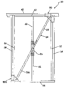
Referring now to the drawings, FIG. 1 shows an embadiment of a framing and
bracing apparatus 30 according to the present invention. Conventional framing
components include vertical studs 32, 34, 36, 38, horizontal plates 40, 42,
and a sill
44. Bracing apparatus includes a head clip 50, sill clip 50a, tension strut
54, and
stud support clip 56. The head clip 50 is attached to the horizontal plates
40, 42 and
the studs 32, 34, while the sill clip 50a is attached to the sill 44 and studs
36, 38.
The head clip 50 and the sill clip 50a may be identical or substantially
identical
depending on the application. For example, in FIG. 1 they are substantially,
but not
exactly, identical because the head clip 50 attaches to two horizontal
members,
horizontal plates 40, 42, while the sill clip 50a attaches to the single
member sill 44,
and accordingly the dimensions vary. The tension strut 54 is bolted or
otherwise
fastened to head clip 50 and sill clip 50a. The tension strut 54, including
two
elongated web members 58, 58a, passes through stud support clip 56, which
supports and is fastened to half length studs 60, 62 that are respectively
attached to
the horizontal plate 42 and sill 44 in a manner known to one of ordinary skill
in the
art. In one embodiment the head clip 50, sill clip 50a, and tension strut 54
are made
of light gauge steel.
As shown in FIG. 2, the head clip 50 includes a horizontal portion 66 and a
vertical portion 68. The horizontal and vertical portions 66, 68 may be made
from a
unitary piece of plate that is bent to a 90 degree angle, or may be separate
pieces
with an abutting and welded edge. For the purposes of description herein, a
unitary
piece of bent plate and separate but joined plates are considered to be
equivalent.
Flanges 70, 72, 74, 76 extend along the edges perpendicular to the 90 degree
bend
and away from the interior 90 degree angle, at 90 degree angles themselves
relative

CA 02478459 2004-08-23
to the respective horizontal and vertical portions so as to allow the flanges
70, 72,
74, 76 to fit around a structural framing member. Holes 78 through the flanges
are
provided for screwing or nailing the head clip 50 to the framing members. The
head
clip 50 further comprises a bracket 80 having two triangular bracket members
82, 84
mounted to the interior angle of the horizontal portion 66 and vertical
portion 68. The
triangular bracket members 82, 84 may be mounted by welding or other means of
attachment known to one of ordinary skill in the art.
FIG. 3 shows an exploded view of an embodiment 30 of the present invention.
The sill clip 50a is fabricated similarly to the head clip 50. fn addition,
one
embodiment includes anchors 90 through the sill clip 50a, such as chemical or
wedge anchors, to be placed into a concrete foundation. Such anchors 90
axially
resist uplift forces.
The tension strut 54 has an adjustable length based on sliding, or
telescoping,
the web members 58, 58aand then fastening them using fasteners 96. Fastening
of
the web members 58, 58a to each other and to the triangular bracket members
82,
84 may be done with, for example, self-tapping screws, pre-drilled holes with
screws
or bolts as shown, or welding. As shown in FIG. 2, the upper end of the
tension strut
58 is mounted to the bracket 80 of the head clip 50 by a bolt 98 that passes
through
holes 100, 102 in the triangular bracket members 82, 84 and through a hole 104
in
the tension strut 54. The holes 100, 102 may be, for example, round, or
slotted as
shown. The lower end 58a of the tension strut 54 is similarly attached to the
sill clip
50a.
The head clip 50 is shown in the side view embodiment 50 of FIG. 4 have a
slotted hole 102 through bracket member 84 for attaching the tension strut 54
to the
11

CA 02478459 2004-08-23
head clip 50. A corresponding opening, slotted hole 100, penetrates the other
bracket member 82 (FIG. 3). A slot 100, 102 may be used instead of a round
hole in
order to avoid compression force on the tension strut 54. As shown in the head
clip
50 and sill clip 50a embodiments of FIGS. 4 and 7, when installed the tension
strut
54 should be as short as possible, with the bolts 98, 98a on the edges of the
slots
100, 100a and slots 102, 102a that are proximate to each other. When using
this
tension strut 54, it is necessary to ensure that the structure itself is
"tight."
Connections should be made in a manner to assure that they will be initially
free of
slack and will not loosen under load reversals or repeated loading. This means
avoiding connections that are loose or that allow movement between the
structural
members. Avoiding loose connections is particularly important in systems
subject to
dynamic loading since relative movement between the structural members leads
to
increased wear and deterioration of the connection.
FIG. 5 and 6 respectively show a front view and a bottom plan view of the
FIG. 4 head clip 50 embodiment. In this embodiment holes 105, 108 are shown
penetrating the vertical portion 68, as well as holes 110, 112 penetrating
horizontal
surface 66. Fasteners through these holes 106, 108, 110, 112 may be used to
provide additional strength in the attachment to the horizontal plates 40, 42
or studs
32, 34 as applicable, or may be omitted.
Likewise, sill clip 50a is shown in the side view of the FIG. 7 embodiment 50a
to have a slotted hole 102a through bracket member 84a for attaching the lower
web
member 58a of the tension strut 54 (FIG. 3) to the sill clip 50a. A
corresponding
slotted hole 100a penetrates the other bracket member 82a (not visible). FIGS.
8
and 9 respectively show a front view and a top plan view of the sill clip 50a.
In this
12

CA 02478459 2004-08-23
embodiment holes 106a, 108a are shown penetrating the vertical portion 68a, as
well as holes 110x, 112a penetrating horizontal surface 66a. These holes 106a,
108a, 110a, 112a may be used to provide additional strength in the attachment
to
the sill or studs as applicable, or may be omitted. In particular, anchors 90
(FIG. 2)
may be provided through holes 110a, 112a and into a base such as a concrete
foundation in order to counteract uplift forces. The uplift forces will act
along the axis
of the anchors 90 as opposed to relying on the fasteners to the sill 44
through the
flanges 70a, 72a that would encounter shear forces. The lower flanges 70a, 72a
of
the sill clip 50a embodiment are not as deep as the upper flanges of the head
clip 50
because the sill clip 50a is fastened to only one member, the sill 44, and the
head
clip is fastened to two members 40, 42.
The tension strut 54 is shown in a nested arrangement in FIG. 10. Upper
portion 58 and lower portion 58a interlock with each other, and are
reciprocally
mounted. The shape of the members 58, 58a in this embodiment is a square C-
member of FIG. 11, with one leg 114, 114a modified to be longer than the other
leg
116, 116a. This allows the nesting shown in FIG. 12, and results in the
telescoping
relative movement of the members 58, 58a. The tension strut 54 is accordingly
able
to be installed in varying heights and widths of panels. Dimensions commonly
encountered may be from eight foot to twelve foot height and two foot to five
foot four
inch width, although the present invention is not limited to these dimensions.
An
example size would be 1.5-inch by 1.5-inch C-member with the leg length
adjustment made by not fully bending the curve 118, 118a of one leg inward to
complete the "C." Alternative shapes may also be used, for example, a
rectangular
13

CA 02478459 2004-08-23
or square tube cross-section shape with one member sized to fit within the
other
member.
An embodiment of a stud support clip 56 is shown in FIGS. 13-17. As shown
in FIGS. 13 and 14, the stud support clip 56 fits around the tension strut 54,
with the
ends of the stud support clip projecting vertically. Each end 120, 122
receives a
portion of a vertical stud 60, 62 either metal or wood, which respectively
extends and
is fastened to the horizontal plate 42 or to the sill 44 as known to one of
ordinary skill
in the art. Each vertical stud 60, 62 and the tension strufi 54 are fastened
to the stud
support clip 56 using fasteners 128 through holes 130, which may be punched,
pre-
drilled, or otherwise formed. Holes in all parts herein may be omitted in
favor of self-
tapping screws or the like.
Conventional spacing of structural framing studs 32, 36 is either 24 inches or
16 inches. Example spacing between studs 32, 36 (FIG. 1) is 48 inches.
Accordingly, in order to provide intermediate studs for attaching sheetrock,
sheeting,
IS or other panels on exterior or interior sides at desired conventional
intervals, one or
more stud support clips 56 and associated studs 60, 62 rnay be provided. For
example, in a 48-inch space, one support clip 56 would be needed to provide 24-
inch
spacing and two support clips 56 would be required to provide 16-inch spacing.
An embodiment of the stud support clip 56 is shown in detail in FIGS. 15-17.
A web 132 is formed inward so as to meet the tension strut 54. Bent portions
134,
136 flare the web 132 outward to vertical portions 138, 140. First flanges
142, 144
each extend from a vertical edge of the vertical portions 138, 140 and form a
90
degree angle with the respective vertical portion 138, 140. Second flanges
146, 148
extend from the free vertical edge of each first flange 142, 144 to form a 90
degree
14

' CA 02478459 2004-08-23
angle. The flanges 142, 144, 146, 148 are sized and shaped to receive the
portions
of studs 60, 62.
As shown in FIG. 18, two channels 180, 182 which mey be cold-rolled, are
mounted to a stud support clip 56. The channels 150, 152 are used for
additional
S support of a wall or sheeting, particularly in commercial installations. As
shown in
FIGS. 18-20, the channels 150, 152 include an elongated flat portion 153, 154
with a
planar portion 155, 156 perpendicular to and at one end of the elongated
portion
153, 154. Mounting holes 157 may be provided.
Another embodiment of a sill clip 50b is shown in FIGS. 21-23. The
construction is similar to the sill clip 50a detailed in FIGS. 7-9. A general
difference
between the two embodiments is that the flanges 160, 162 in the sill clip 50b
of
FIGS. 21-23 are bent upward rather than downward; the flanges 70a, 70b in the
sill
clip 50a of FIGS. 7-9 are bent downward. This embodiment 50b may be
particularly
useful for applying to steel framing.
I S FIGS. 24-26 show another embodiment of a stud support clip 170. The
construction is similar to the stud support clip 56 shown in FIGS. 15-17. The
stud
support clip of FIGS. 24-26, however, has opposing vertical webs 172, 174. A
tension strut 54 (not shown) passes through the opening between the webs 172,
174. Bent and angled portions 176, 178, 180, 182 flare outward from the
opposing
vertical webs 172, 174. A rectangular sleeve 184, 186 is provided at top and
bottom
of the clip 130 attached to the flared portions. Each sleeve 184, 186 receives
a
portion of a vertical stud 60, 62 (not shown) either metal or wood, which
respectively
extends and is fastened to the horizontal plate 42 or to the sill 44 as known
to one of
ordinary skill in the art. Each vertical stud 60, 62 and the tension strut 54
are

CA 02478459 2004-08-23
fastened to the clip 170 using fasteners (not shown) through holes 188, which
may
be punched, pre-drilled, or otherwise formed.
The bracing of the present invention may be provided in a variety of sizes.
For example, the clips may be sized to conform to standard wood framing member
sizes and standard light gauge steel framing sizes, or to larger or custom
sizes. The
tension strut may be sized in accordance with design considerations of a
particular
application. Further, a variety of connection means to the foundation could be
used.
it should also be understood that not every feature of the bracing apparatus
described is necessary to implement the invention as claimed in any particular
one of
the appended claims. Various elements of lateral and uplift force resistance
arrangements may be used to fully practice the invention. It should also be
understood that throughout this disclosure, where a process or method is shown
or
described, the steps of the method may be performed in any order or
simultaneously, unless it is clear from the context that one step depends on
another
being performed first.
Specific embodiments of an invention are described herein. One of ordinary
skill in the structural engineering arts will recognize that the invention has
other
applications in other environments. in fact, many embodiments and
implementations
are possible. For example, the bracing of the present invention may be applied
to
other types of construction, and the securing of the tension strut may be used
in
other applications where lateral forces and uplift need to be resisted. In
addition, the
recitation "means for" is intended to evoke a means-plus-function reading of
an
element in a claim, whereas, any elements hat do not specifically use the
recitation
"means for," are not intended to be read as means-plus-function elements, even
if
16

CA 02478459 2004-08-23
they otherwise include the word "means." The following claims are in no way
intended to limit the scope of the invention to the specific embodiments
described.
17

Dessin représentatif
Une figure unique qui représente un dessin illustrant l'invention.
États administratifs

2024-08-01 : Dans le cadre de la transition vers les Brevets de nouvelle génération (BNG), la base de données sur les brevets canadiens (BDBC) contient désormais un Historique d'événement plus détaillé, qui reproduit le Journal des événements de notre nouvelle solution interne.

Veuillez noter que les événements débutant par « Inactive : » se réfèrent à des événements qui ne sont plus utilisés dans notre nouvelle solution interne.

Pour une meilleure compréhension de l'état de la demande ou brevet qui figure sur cette page, la rubrique Mise en garde , et les descriptions de Brevet , Historique d'événement , Taxes périodiques et Historique des paiements devraient être consultées.

Historique d'événement

Description Date
Inactive : Morte - Aucune rép. à dem. art.29 Règles 2008-06-12
Demande non rétablie avant l'échéance 2008-06-12
Réputée abandonnée - omission de répondre à un avis sur les taxes pour le maintien en état 2007-08-23
Inactive : Abandon. - Aucune rép dem par.30(2) Règles 2007-06-12
Inactive : Abandon. - Aucune rép. dem. art.29 Règles 2007-06-12
Inactive : Dem. de l'examinateur art.29 Règles 2006-12-12
Inactive : Dem. de l'examinateur par.30(2) Règles 2006-12-12
Demande publiée (accessible au public) 2006-01-09
Inactive : Page couverture publiée 2006-01-08
Lettre envoyée 2005-07-07
Inactive : Transfert individuel 2005-06-02
Lettre envoyée 2005-04-25
Exigences pour une requête d'examen - jugée conforme 2005-04-06
Toutes les exigences pour l'examen - jugée conforme 2005-04-06
Requête d'examen reçue 2005-04-06
Inactive : CIB en 1re position 2004-12-02
Inactive : Lettre de courtoisie - Preuve 2004-10-12
Inactive : Inventeur supprimé 2004-10-08
Inactive : Certificat de dépôt - Sans RE (Anglais) 2004-10-08
Demande reçue - nationale ordinaire 2004-10-04

Historique d'abandonnement

Date d'abandonnement Raison Date de rétablissement
2007-08-23

Taxes périodiques

Le dernier paiement a été reçu le 2006-08-14

Avis : Si le paiement en totalité n'a pas été reçu au plus tard à la date indiquée, une taxe supplémentaire peut être imposée, soit une des taxes suivantes :

  • taxe de rétablissement ;
  • taxe pour paiement en souffrance ; ou
  • taxe additionnelle pour le renversement d'une péremption réputée.

Les taxes sur les brevets sont ajustées au 1er janvier de chaque année. Les montants ci-dessus sont les montants actuels s'ils sont reçus au plus tard le 31 décembre de l'année en cours.
Veuillez vous référer à la page web des taxes sur les brevets de l'OPIC pour voir tous les montants actuels des taxes.

Historique des taxes

Type de taxes Anniversaire Échéance Date payée
Taxe pour le dépôt - générale 2004-08-23
Requête d'examen - générale 2005-04-06
Enregistrement d'un document 2005-06-02
TM (demande, 2e anniv.) - générale 02 2006-08-23 2006-08-14
Titulaires au dossier

Les titulaires actuels et antérieures au dossier sont affichés en ordre alphabétique.

Titulaires actuels au dossier
NUCON STEEL CORPORATION
Titulaires antérieures au dossier
COURTNEY J. HANSON
Les propriétaires antérieurs qui ne figurent pas dans la liste des « Propriétaires au dossier » apparaîtront dans d'autres documents au dossier.
Documents

Pour visionner les fichiers sélectionnés, entrer le code reCAPTCHA :


Pour visualiser une image, cliquer sur un lien dans la colonne description du document (Temporairement non-disponible). Pour télécharger l'image (les images), cliquer l'une ou plusieurs cases à cocher dans la première colonne et ensuite cliquer sur le bouton "Télécharger sélection en format PDF (archive Zip)" ou le bouton "Télécharger sélection (en un fichier PDF fusionné)".

Liste des documents de brevet publiés et non publiés sur la BDBC .

Si vous avez des difficultés à accéder au contenu, veuillez communiquer avec le Centre de services à la clientèle au 1-866-997-1936, ou envoyer un courriel au Centre de service à la clientèle de l'OPIC.

({010=Tous les documents, 020=Au moment du dépôt, 030=Au moment de la mise à la disponibilité du public, 040=À la délivrance, 050=Examen, 060=Correspondance reçue, 070=Divers, 080=Correspondance envoyée, 090=Paiement})


Description du
Document 
Date
(aaaa-mm-jj) 
Nombre de pages   Taille de l'image (Ko) 
Description 2004-08-22 17 773
Abrégé 2004-08-22 1 21
Revendications 2004-08-22 20 637
Dessins 2004-08-22 11 206
Dessin représentatif 2005-12-12 1 7
Certificat de dépôt (anglais) 2004-10-07 1 168
Accusé de réception de la requête d'examen 2005-04-24 1 176
Courtoisie - Certificat d'enregistrement (document(s) connexe(s)) 2005-07-06 1 114
Rappel de taxe de maintien due 2006-04-24 1 112
Courtoisie - Lettre d'abandon (R30(2)) 2007-09-03 1 166
Courtoisie - Lettre d'abandon (R29) 2007-09-03 1 166
Courtoisie - Lettre d'abandon (taxe de maintien en état) 2007-10-17 1 173
Correspondance 2004-10-07 1 27
Taxes 2006-08-13 1 28