Note : Les descriptions sont présentées dans la langue officielle dans laquelle elles ont été soumises.
CA 02478917 2004-09-10
WO 03/078283 PCT/IB03/00926
1
An automated system and a method for the delivery and
distribution of articles in groups and a device and a method
for grouping articles together
The present invention relates to an automated system and to a
method for the delivery and distribution of articles in
groups, as well as to a device and to a method for grouping
articles together.
A particularly important, but non-limiting, field of
application of the present invention is that of the
management of stores of drugs and other pharmaceutical or
medical products, with particular reference to the selective
distribution of these products within hospital establishments
in accordance with requirements for the administration of the
products to individual patients. There is an ever greater
need to provide automatic systems and stores in which medical
products are stored in individual doses and from which these
products can be withdrawn, grouped together in various ways,
on the basis of instructions or orders which reflect the
specific prescriptions for the use of medical products and
for the administration of drugs to the various patients under
treatment.
For simplicity and clarity of explanation, reference will be
made below to the grouping-together of medical products but,
naturally, the present invention may equally well be applied
to other fields which have similar problems such as, for
example, for fulfilling orders for spare parts for motor
vehicles or other machines, for the grouping-together of
components for the manufacture of industrial products such
as, for example, electronic components, small metal parts,
and the like.
Many known systems for the automated withdrawal of medical
products from a store, in which the products are preferably
CA 02478917 2004-09-10
WO 03/078283 PCT/IB03/00926
2
stored in individual doses, provide for the selection of all
of the product doses which make up the individual orders and
for their delivery in groups at the output by depositing them
in cases, boxes, trays, bags or other similar containers,
each of which corresponds to a particular order which
represents, for example, the prescription for the daily
administration of drugs to a specific patient.
These known systems have several disadvantages, amongst which
the most obvious is the need to provide a sufficient number
of containers into which the automated withdrawal and
delivery system can discharge the various products which make
up the various orders. This method of operation leads to a
complex organization, which can usually be managed only
manually, if the containers, for example, the cases or boxes,
have to be reused. In fact, once the prescribed drugs have
been administered to the patients, the empty containers have
to be collected from each patient and returned to the
automated withdrawal and delivery system. If, on the other
hand, disposable containers, for example, paper or plastics
envelopes or bags, are used, the overall running cost of the
automated system may become particularly high because of the
large number of disposable containers which have to be
provided and used purely to keep the products physically
grouped together. In this connection, it will suffice to
consider the large numbers of orders for the administration
of medical products which an automated system of the type
indicated above is required to fulfil daily, even in small
hospital establishments.
The above-mentioned disadvantage is aggravated in situations
in which the individual prescriptions for drugs or medical
products involve a small number of products in individual
doses. Clearly, the burden of the management of the empty
containers, or the cost of the disposable containers, is less
the larger is the number of products included in each
CA 02478917 2004-09-10
WO 03/078283 PCT/IB03/00926
3
individual order and grouped together in each individual
container. In general, however, and in particular for the
daily administration of pharmaceutical and medical products
to patients in hospital establishments, it is possible to
increase the number of products to be grouped together for
each individual order only at the expense of the efficacy and
overall usefulness of the automated system for the withdrawal
and delivery of products for the final purposes for which it
is intended.
There is a risk that the disadvantages indicated above will
greatly limit the spread of automated systems for the
management or orders for medical prescriptions, which could
otherwise contribute enormously to the reduction of the
management costs of hospital establishments, increasing their
overall efficiency, enabling the personnel employed in the
manual selection and distribution of drugs and of medical
products in general to be assigned to more skilled
activities.
The object of the present invention is therefore to overcome
the disadvantages described above by providing a device and a
method for the grouping-together of articles, which device
and method are simple, economical and efficient, particularly
but not exclusively when used for grouping together drugs and
medical products to be distributed within automated systems
used in hospital establishments.
In order to achieve the object indicated above, the subject
of the invention is an automated system and a method for the
delivery and distribution of articles in groups, as well as a
device and a method for grouping articles together, having
the characteristics indicated in the appended claims.
According to an advantageous characteristic of the invention,
the groups or bundles of articles grouped together are
CA 02478917 2004-09-10
WO 03/078283 PCT/IB03/00926
4
identified individually by respective labels connected to the
bundles and preferably generated at the moment when the
products are grouped together.
The device of the present invention provides for the various
articles to be grouped together in a bundle held together by
a restraining means, preferably of elongate shape, such as,
for example, a thread or a strip, connected to each product
of an individual group, for example, by means of a glue,
clips, or other similar means. In a preferred embodiment,
the thread or strip is inserted through holes provided in the
articles before being closed into a loop. In particular, the
restraining means may be a thread or strip of plastics
material or other material which can be welded to form the
closed loop, or may be a notched band or other member
provided with similar closure means.
In a preferred embodiment, the automatic device comprises a
load-bearing structure for supporting the various members of
the machine, including guide means for providing the
restraining means with an obligatory path to be followed
during its application, comprising at least one fixed guide
member and one guide member which is movable relative to the
load-bearing structure, and feed means for supplying the
restraining means, the feed means being operable in a direct-
feed mode in order to urge the restraining means through the
guide means, and in a reverse-feed mode in order to return
the restraining means, and means for retaining the
restraining means. The guide means form a path for the
restraining means through the packages of products.
A particular advantage of this device is that the grouping-
together of the articles can be achieved by the insertion of
the restraining means through holes which already exist in
the packages or which may possibly be created automatically
when the articles are grouped together. There is thus no
CA 02478917 2004-09-10
WO 03/078283 PCT/IB03/00926
need to squeeze the products into close contact with one
another, possibly damaging them. Moreover, the device is
usable particularly advantageously with packages such as bags
or blister packs which are already provided with respective
slots, eyelets, or the like for the insertion of the guide
means. In this case, the device can easily be incorporated
in a system for the storage and withdrawal of the packages in
which bags or the like, suspended on suitable supports by
means of the slots, are slipped onto the guide means in order
to form groups to be held together.
Further characteristics and advantages will become clear from
the following detailed description given with reference to
the appended drawings, provided purely by way of non-limiting
example, in which:
Figure 1 is a schematic view of an automatic system for the
withdrawal and delivery of articles provided with a device
and operating in accordance with a method according to the
present invention,
Figure 2 is a side elevational view of an embodiment of a
device for grouping articles together in accordance with the
present invention, arranged for the direct feed of the
restraining means,
Figure 3 is a schematic side elevational view of the device
of Figure 2, in which the outer shapes of the main members
are shown and in which the guide means are in a position for
locking the restraining means,
Figure 4 is a front elevational view of the device of Figure
2, shown partially in section and on an enlarged scale,
Figure 5 is a section taken on the line V-V of Figure 2
through the fixed guide member, on an enlarged scale,
CA 02478917 2004-09-10
WO 03/078283 PCT/IB03/00926
6
Figure 6 is a front view of an example of the grouping-
together of articles achieved by a system according to the
present invention,
Figure 7 is a rear view of the grouping of Figure 6,
Figure 8 is a front view of a variant of the grouping of
articles of Figures 6 and 7, and
Figures 9 and 10 are perspective views of two examples of the
grouping-together of articles with restraining means closed
into a loop.
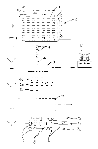
Figure 1 shows schematically an automatic system for the
withdrawal and delivery or distribution of articles 1,
comprising a store 2 in which the articles 1 are stored in an
orderly manner in accordance with a predetermined physical
and logical structure, for example, in locations identified
by three-dimensional coordinates x, y, z, so that they can be
identified and collected by a collection and delivery device
3 provided with collecting means 4. An electronic processor
is programmed to know the location of the individual
products 1 with reference to the coordinates x, y and is
connected or otherwise associated with the collecting device
3 in order to control it and address it selectively for the
collection of products forming part of orders G1, G2, G3
entered and stored in the processor 5 in known manner. The
collection and delivery device 3 outputs the products 1,
grouped together logically in sets 6a, 6b, 6c, corresponding
to the orders G1, G2, G3. Systems of this type, which are
particularly suitable for the storage of packages of
individual doses of pharmaceutical products, are known, for
example, from the documents US-5468110, US-5880443 and US-
6217273 and will not therefore be discussed in further
detail. It may, however, be useful to mention that the
CA 02478917 2004-09-10
WO 03/078283 PCT/IB03/00926
7
above-mentioned documents of the prior art describe storage
systems in which the various products are stored in an
orderly manner in locations disposed on one level and hence
identified by two Cartesian coordinates x, y, or disposed on
a cylinder, and hence identified by two polar coordinates oc,
z. Although the present invention is described and
illustrated with reference to the three-dimensional store 2
of Figure 1, it may also be applied, with functionally
similar results, to the two-dimensional stores of the prior
art, as well as to simpler one-dimensional systems, for
example, belt conveyors and the like.
The logical sets of products 6a, 6b, 6c are supplied in
succession to a grouping device 10 which, as will be
described further below, outputs packs, groups, or bundles
7a, 7b, 7c of articles 1 physically connected to one another
by restraining means 8, and corresponding to the sets of
articles 6a, 6b, 6c input and to the orders G1, G2, G3 stored
in the electronic processor 5. A corresponding
identification label 9, prepared beforehand and supplied as
an input to the grouping device 10, or generated on the spot,
for example, by means of a printer (not shown) operatively
connected to the electronic processor 5, may be associated
with each group or bundle 7a, 7b, 7c of articles, and
preferably restrained on the restraining means 8.
The restraining means 8 is preferably of elongate shape and
comprises, for example, a thread or strip which is connected
to each product of a single group by means of a glue, clips,
or other similar means. Figures 6 and 7 show a particular
embodiment in which the articles grouped together are
constituted by bags 101 each of which contains medical or
pharmaceutical products 102, 103, 104, 105. The bags 101 are
fixed, at least by a portion thereof, to one face 108a of the
strip 108 of fabric, paper, rubber, or other material, so as
to form a group of articles grouped together. The bags 101
CA 02478917 2004-09-10
WO 03/078283 PCT/IB03/00926
may be fixed to the strip 108 by means of a glue or
mechanically by means of clips, staples, or the like.
The strip 108 may itself act as an informative label for the
group of articles, by virtue of the fact that the data 109
characterizing the order or instructions for the various
products contained in the bags 101, as well as possibly the
destination of the order, for example, the department and/or
the patient to whom the products are to be administered, may
be printed on the other face 108b of the strip, opposite that
to which the bags 101 are fixed. In the variant of Figure 8,
the bags 101 are fixed to the strip 108 by means of adhesive
labels 110, each of which may give informative data specific
to each product 102, 103, 104, 105 and/or general data
relating to the order or instructions corresponding to the
grouping of the articles.
In a preferred embodiment, the thread or strip is inserted
through holes provided in the articles, before being closed
into a loop. In the embodiment of Figure 9, a notched band
111 of generally known type is used to group together and
restrain a set of bags 112, in each of which there is a hole
or opening 113 which can usefully also be used for suspending
the bags in the store 2 mentioned above with reference to
Figure 1.
In particular, as shown in Figure 10, the restraining means
may be a thread or strip 114 of plastics material or other
material suitable for being welded at the point 115 to form
the closed loop 116 which groups the bags 112 together. An
informative label 117, also provided with a hole or opening
118, may be associated with the group of bags 112.
With regard to this latter solution for the grouping-together
of articles and with reference now to Figure 2, a particular
embodiment of the device 10 for grouping together and
CA 02478917 2004-09-10
WO 03/078283 PCT/IB03/00926
9
restraining the articles 1, in particular but not exclusively
individual packages or bags of products, comprises a load-
bearing structure 12, preferably formed by profiled sections
14 of various shapes, assembled to form a frame. A unit 16
for supporting and moving the means for restraining the
products, in particular a thread 18, is disposed on the load-
bearing structure 12. The unit 16 comprises a motor 20,
preferably an electric motor, and means for holding the
thread 18, in particular a reel 22. Naturally, for the
purposes of the implementation of the device 10, the thread
18 may be replaced by functionally similar elements such as
strings or bands of material that can be welded, for example,
thermoplastic material.
A feed unit 24 is also mounted on the frame 12 in a position
such as to receive the thread 18 output from the reel 22.
The feed unit 24 comprises a motor 26, at least one drive
roller 28 for the thread 18, and a thrust roller 30, disposed
opposite the drive roller 28 and mounted, together with an
idle roller 32, on a pivoting arm 34. A linear actuator 36
mounted on the frame 12 by means of a support bracket 37, is
connected to the pivoting arm 34 by means of a rod 38
provided with a collar 40 which slides in a tubular body 42
so as to compress a spring 44.
A guide for the thread 18, generally indicated 46, is mounted
on the frame 12 at the output of the feed unit 24 and
comprises a fixed portion 48 and a movable portion 52 which
can be closed selectively onto the fixed portion 48 to form,
as a whole, a closed guide path. The guide 46 preferably has
an open ring-shaped cross-section (see Figure 5) in which a
channel 46a has an opening 46b facing towards the inside of
the guide path formed by the fixed and movable portions 48
and 52 of the guide 46.
CA 02478917 2004-09-10
WO 03/078283 PCT/IB03/00926
A lead-in input bush 47 for the thread 18 is positioned at
one end of the fixed guide portion 48. The fixed guide
portion 48 also comprises a fixed guide member 50 which,
preferably but in non-limiting manner, extends in a
horizontal direction.
The movable guide portion 52 is articulated to the frame 12
so as to be pivotable about a horizontal axis X-X as
indicated by the arrow A in Figure 2. The movable guide
portion 52, preferably but in non-limiting manner, comprises
a guide portion 54 which, in the closed configuration of the
guide 46 shown in Figure 2, is substantially parallel to the
fixed guide member 50 of the fixed guide portion 48 and is
extended by a connecting portion 56. The fixed guide member
50 has an end 58 by which it is connected to the connecting
portion 56 and in which a locating abutment 60 is formed for
the movable guide portion 52. The movable guide portion 52
has, at the end remote from the connecting portion 56, a
shaped portion 62 having the function of a jaw, the purpose
of which will become clearer from the following description.
An actuator unit ~4 is mounted on the frame 12 in order to
move the movable guide portion 52 selectively and comprises,
in the non-limiting embodiment of Figure 2, a linear actuator
66 fixed to the frame 12 by means of a bracket 68 and an
articulated system 70 preferably comprising a ball joint 72
and a hinge 74 fixed to the movable guide portion 52.
The device 10 also comprises means 76 for cutting the thread
18, comprising a blade 78 fitted in the manner of a
guillotine, in a compartment 80 formed at the outlet of the
lead-in bush 47, transverse the feed axis of the thread 18,
and a linear actuator 82 fixed, for example, to the base of
the frame 12 by means of a bracket 84, and connected to the
blade 78 by means of a ball joint 86.
CA 02478917 2004-09-10
WO 03/078283 PCT/IB03/00926
11
Inside the closed path formed by the guide 46, in the
vicinity of the shaped portion 62, there is a retaining
element for selectively restraining the thread 18,. and
preferably comprising a block 88 suitable for providing an
abutment surface. With reference to Figure 3, the block 88
is connected, by means of a rod 90, to an actuator 92 which
in turn is fixed to the frame 12 by means of a bracket 94.
The drive roller 28, preferably but in non-limiting manner,
has a peripheral groove 96 for guiding the thread 18 and is
mounted on a shaft 98 supported, for example, by two plain
bearings 100 fixed to the frame 12 in a manner not shown.
The shaft 98 is connected to the drive shaft 102 of the motor
26 by means of a reduction unit 104, for example, an
epicyclic unit.
During the normal operation of the device 10, the thread 18
passes between the drive roller 28 and the thrust roller 30
whilst the idle roller 32 ensures that the thread coming from
the reel 22 is not subject to excessive curvature. The
thrust roller 30 has the function of keeping the thread 18
pressed against the drive roller 28 so that this roller can
selectively transmit to it a forward movement towards the
guide 46, in a direct-feed mode, or an opposite movement in a
reverse-feed mode in which the thread 18 is returned from the
guide 46. The actuator 82 ensures the necessary pressure
which is calibrated by the preloading of the spring 44. The
thread 18 at the output of the feed means 24 is received by
the lead-in bush 47 which supplies an input of the guide 46.
In the configuration described up to now, the device 10 is
arranged for performing a cycle for the grouping-together and
tying of articles, an example of which is given below but
which should not be considered as limiting of the
possibilities for the use of the device 10 or, more
generally, of the present invention.
CA 02478917 2004-09-10
WO 03/078283 PCT/IB03/00926
12
In an initial step, the movable guide portion 52 is raised
away from the fixed guide portion 50, by means of the
actuator 66. Individual packages of products, not shown,
which are to be grouped together and restrained relative to
one another, are positioned in a manner such that the at
least one fixed guide member 50 extends through respective
slots, eyelets, or the like, suitably provided therein. The
movable guide portion 52 is then closed so that the guide
means 46 form a substantially closed path through the
individual packages.
In a subsequent step, the feed means 24 are operated in
direct-feed mode by the drive means 26 so as to cause the
thread 18 to pass through the guide 46 until an overlap is
created between the free end 106 of the thread 18 and the
portion of thread 18 input into the guide 46. The movable
guide portion 54 is then raised again by the actuator 66 so
that, by virtue of its pivoting about the axis X-X, the
shaped portion 62 squeezes the free end 106 of the thread 18
against the block 88, holding it in a clamped position, as
shown in Figure 3. At this point, the feed means 24 are
operated in reverse-feed mode, in order to recover the thread
18 until the size of the closed loop which it forms through
the individual packages is reduced to a predetermined
dimensions. During this step, the thread 18 is free to leave
the guide 46, by virtue of the opening 46b provided in the
channel 46a (see Figure 5) so that the thread 18 can be
recovered and the individual packages of products can be
grouped together in a pack or bundle.
The body of the thread 18 and its free end 106, which are
superimposed, are then joined or welded together, for
example, by means of a heat-sealing rod which is moved
selectively towards the region of intersection and
superimposition of the thread 18 and its end 106. The blade
78, operated by the actuator 82, then separates the loop of
CA 02478917 2004-09-10
WO 03/078283 PCT/IB03/00926
13
thread 18 restraining the individual packages from the rest
of the thread 18 wound on the reel 22. At the end of the
cycle, the actuator 92 removes the block 88 from the guide
46, allowing the restrained packages to be released.
According to a particularly advantageous variant, the heat-
sealing rod may also incorporate the separation function of
the blade 78, or may act simultaneously therewith.
According to another particularly advantageous variant, the
device 10 is associated with the collection and delivery
device 3 of Figure 1 which may comprise a pin or other member
on which the products 1 of each logical set 6a, 6b, 6c making
up a specific order G1, G2, G3 are suspended. The collecting
member 4 of the collection and delivery device 3 and/or the
guide 46 of the device 10 can be inclined selectively, so
that the fixed guide portion 48 can receive the individual
packages of products 1 by gravity. In the preferred
situation, in which the guide 46 is selectively inclinable,
an opposite inclination of the guide 46 to that used for the
collection of the individual package from the collection and
delivery device 3 enables the groups or bundles 7a, 7b, 7c of
articles physically connected to one another to be released
and discharged automatically.
As mentioned above, the cycle for the grouping-together of
the articles 1 by means of the device 10 described above may
also comprise the insertion, in the group or bundle of
articles restrained by the thread 18, of a label, preferably
but in non-limiting manner, generated by printing means
connected to the electronic processor 5, and giving data
useful for the identification of the articles grouped
together and/or of their final destination of use within the
system for the distribution of the articles 1.
CA 02478917 2004-09-10
WO 03/078283 PCT/IB03/00926
14
Naturally, the principle of the invention remaining the same,
the details of construction and forms of embodiment may vary
widely with respect to those described and illustrated,
without thereby departing from the scope of the present
invention.