Sélection de la langue

Search

Sommaire du brevet 2479547 

Énoncé de désistement de responsabilité concernant l'information provenant de tiers

Une partie des informations de ce site Web a été fournie par des sources externes. Le gouvernement du Canada n'assume aucune responsabilité concernant la précision, l'actualité ou la fiabilité des informations fournies par les sources externes. Les utilisateurs qui désirent employer cette information devraient consulter directement la source des informations. Le contenu fourni par les sources externes n'est pas assujetti aux exigences sur les langues officielles, la protection des renseignements personnels et l'accessibilité.

Disponibilité de l'Abrégé et des Revendications

L'apparition de différences dans le texte et l'image des Revendications et de l'Abrégé dépend du moment auquel le document est publié. Les textes des Revendications et de l'Abrégé sont affichés :

  • lorsque la demande peut être examinée par le public;
  • lorsque le brevet est émis (délivrance).
(12) Brevet: (11) CA 2479547
(54) Titre français: RAIL DE TRANSITION ET METHODE DE PRODUCTION DU RAIL DE TRANSITION
(54) Titre anglais: TRANSITION RAIL AND METHOD FOR PRODUCING SAID TRANSITION RAIL
Statut: Périmé et au-delà du délai pour l’annulation
Données bibliographiques
(51) Classification internationale des brevets (CIB):
  • B21K 07/02 (2006.01)
  • B21K 09/00 (2006.01)
  • E01B 11/16 (2006.01)
(72) Inventeurs :
  • JAEGER, HELMUT (Autriche)
  • HOELZL, WOLFGANG (Autriche)
(73) Titulaires :
  • VAE EISENBAHNSYSTEME GMBH
  • VAE GMBH
(71) Demandeurs :
  • VAE EISENBAHNSYSTEME GMBH (Autriche)
  • VAE GMBH (Autriche)
(74) Agent: MARKS & CLERK
(74) Co-agent:
(45) Délivré: 2008-10-07
(86) Date de dépôt PCT: 2003-04-04
(87) Mise à la disponibilité du public: 2003-10-16
Requête d'examen: 2005-04-01
Licence disponible: S.O.
Cédé au domaine public: S.O.
(25) Langue des documents déposés: Anglais

Traité de coopération en matière de brevets (PCT): Oui
(86) Numéro de la demande PCT: PCT/AT2003/000099
(87) Numéro de publication internationale PCT: AT2003000099
(85) Entrée nationale: 2004-09-16

(30) Données de priorité de la demande:
Numéro de la demande Pays / territoire Date
A 527/2002 (Autriche) 2002-04-04

Abrégés

Abrégé français

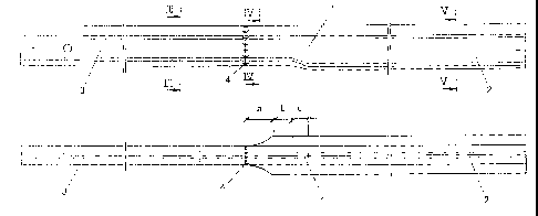
L'invention concerne un rail de raccordement (1) servant à relier des rails de section transversale (2,3) différente et comprenant deux zones de raccordement (a,c). Dans la première zone de raccordement (c), le profil transversal ayant la plus grande hauteur est modifié pour avoir une hauteur de profil moindre, et dans la deuxième zone de raccordement (a), située en aval, le patin du rail est façonné pour être adapté au nouveau profil du patin du rail suivant. Le procédé pour fabriquer ce rail de raccordement est caractérisé en ce que ledit rail de raccordement est d'abord chauffé et placé dans un moule pour être moulé par pression, puis l'âme du rail est modifiée et le rail est pressé dans le sens de la hauteur du profil, et enfin, la transformation complète du patin du rail est alors réalisée mécaniquement.


Abrégé anglais


In a transition rail (1) for the connection of rails having
different rail cross sections (2, 3), the transition rail (1)
comprises two transition zones (a,c), wherein in a first
transition zone (c) the larger-height cross-sectional profile
is reshaped to transition into a smaller profile height and in
the following, second transition zone (a) the rail foot is
worked to match the new profile of the consecutive rail foot.
The method for producing the transition rail is characterized
in that the transition rail is at first heated and introduced
into a press mold, whereupon the rail is reshaped in the web
region and pressed in the direction of the profile height, and
that the rail foot is mechanically worked following complete
reshaping.

Revendications

Note : Les revendications sont présentées dans la langue officielle dans laquelle elles ont été soumises.


-7-
The embodiments of the invention in which an exclusive
property or privilege is claimed are defined as follows:
1. A transition rail for connection of rails, wherein a
first rail has a larger-height cross-sectional profile than
a second rail, wherein the transition rail comprises:
a first transition zone, wherein the larger-height cross-
sectional profile transitions into a smaller-height cross-
sectional profile while the width profile of a rail foot of
the first rail is kept constant; and
a second transition zone having the smaller-height cross-
sectional profile, wherein a rail foot of the second
transition zone transitions into a profile of a rail foot
of the second rail while the cross-sectional profile height
is kept constant.
2. A transition rail according to claim 1, wherein the
second transition zone is arranged closer to a free end of
the transition rail than the first transition zone.
3. A transition rail according to claim 1 or 2, wherein a
zone of constant cross-sectional shape is arranged between
the first transition zone and the second transition zone.
4. A method for producing a transition rail as defined in
claim 1, 2 or 3, wherein the transition rail is at first
heated and introduced into a press mold, whereupon the
transition rail is reshaped in a web region and pressed in
the direction of the profile height, wherein the rail foot
of the transition rail is mechanically worked following
reshaping.

-8-
5. A method according to claim 4, wherein the rail foot
of the transition rail is machined.
6. A method according to claim 4, wherein the second
transition zone of the transition rail, in which the width
of the rail foot decreases, is designed to be rounded in
top view.

Description

Note : Les descriptions sont présentées dans la langue officielle dans laquelle elles ont été soumises.


CA 02479547 2004-09-16 ~
i
- 1 -
Transition Rail and Method for Producing Said Transition Rail
The invention relates to a transition rail for the connection
of rails having different rail cross sections and a method for
producing such a transition rail.
In modern railway traffic, increasing axial loads are applied
such that load limit ranges of the running track may be
readily exceeded. High loads will occur in the transition zone
particularly in regions or rail portions where the rolling
load moves from one rail profile to another rail profile. Such
transition zones are not only known in switch regions and, in
particular, at the transition from standard rails to spring
tongues. Asymmetric thick-web rail profiles as are used, for
instance, in known spring tongue and spring rail switches for
railways, must be connected to rail profiles having larger
heights. During rehabilitation works on rail bodies, it may
however also happen that older rail profiles will have to be
adapted to more modern rail profiles, such different rail
profiles differing not only in terms of height, but also in
regard to the widths of their feet.
Among the known measures for the production of such transition
pieces or transition rails, it was, for instance, proposed in
DE 828 792 C to reforge asymmetric thick-web rail profiles
into rail profiles having larger heights, the asymmetric
thick-web rail profiles in that known method having been
reforged to at least approximately symmetric profiles without
any substantial enlargement of the profile height and the
profile height having subsequently been obtained by
deformation of the web.
Yet, as in DE 33 33 700 C, the transition piece in that case
is formed in manner that the parameters to be changed are
being changed substantially all at one time, an adaptation
both of the height of the web and of the foot of the rail
having been effected over the same length of the transition

CA 02479547 2004-09-16
- 2 -
rail piece. A transition from one rail profile to another rail
profile over as short a length as possible was to be ensured
by the aid of forged fittings.
EP 1 013 826 still also departs from the conviction that a
substantially continuous geometric course is to be reached in
the zone of transition from one rail profile to another rail
profile, appropriate adaptations having to be effected in a
connection-side end region.
The invention aims to provide a transition rail of the
initially defined kind, by which it is feasible to
interconnect rails having different rail cross sections and
rail profiles, which allows for even higher wheel loads
without local overloading and stress concentration, and which,
as a result, is designed to be break-proof to a higher extent
than hitherto known transition rails. To solve this object,
the transition rail according to the invention is essentially
characterized in that the transition rail comprises two
transition zones, wherein in a first transition zone the
larger-height cross-sectional profile is reshaped to
transition into a smaller profile height and in the following,
second transition zone having the smaller profile height the
rail foot is worked to match the new profile of the
consecutive rail foot. As in contrast to the prior art, it is,
thus, proposed according to the invention to carry out the
required adaptations separately in spatially separated
transition zones and merely reduce the profile height in a
first partial region and adapt the rail foot to the new
profile only in a spatially separated, further partial region.
A reduction of the profile height, as is obtained in a
particularly simple manner by upsetting or pressing, naturally
results in an increase of other dimensions and, in particular,
the width of the foot in this partial region under an
appropriate lateral pressing force exerted on the web. Due to
the fact that no additional method steps or shape adaptation
steps are, at the same time, carried out in such changing

CA 02479547 2004-09-16
- 3 -
partial regions, it has now surprisingly turned out that
stress concentrations as observed in configurations in which
height and foot-width profile changes are effected in the same
cross section will no longer occur and that, overall, the
breaking resistance of such a transition rail can, therefore,
be substantially enhanced even under extreme axial loads. This
surprising result could subsequently be verified by a
computational model in which a stress determination was
appropriately modeled by a finite elements model. In that
computational model, the axial force occurring was introduced
as a surface pressure, and it could be demonstrated that the
stress concentrations clearly observed with known
configurations would no longer occur. Between the two partial
regions separately adapted to the respectively new geometry,
also a neutral intermediate region, i.e., a region of constant
cross-sectional shape, may preferably be provided in order to
obtain a further stress concentration reduction between the
two deformation zones.
A further preferred configuration will result if the second
transition zone, to which the lower profile height has already
been imparted and whose rail foot has been worked to match the
new profile of the consecutive rail foot, is arranged closer
to the free end of the transition rail than the first
transition zone. On the free end of the transition rail,
welding with the connector rail having the smaller profile
height and the modified rail foot is effected, whereby, due to
the fact that the second, merely mechanically worked
transition zone is arranged closer to the welding site, stress
concentrations as might possibly occur in the first transition
zone formed by reshaping will be kept away from the welding
site.
The method according to the invention, for producing a
transition rail of this type is essentially characterized in
that the transition rail is at first heated and introduced
into a press mold, whereupon the rail is reshaped in the web

CA 02479547 2004-09-16
- 4 -
region and pressed in the direction of the profile height, and
that the rail foot is mechanically worked following complete
reshaping. By merely effecting pressing in a first method step
after heating, it is feasible to deform the transition rail to
the desired profile height, wherein, by using a press form,
also the web width can be brought to the desired measure, or
kept at the desired measure. It is only after such a complete
reshaping naturally extending over a defined axial length of
the transition rail that the second adaptation is effected,
the rail foot being mechanically worked after this. In doing
so, the rail foot is advantageously machined, thus at the same
time enabling the realization of the transition from a wider
to a narrower rail foot with an appropriate rounding while
observing defined radii. In this respect, the configuration is
advantageously devised such that the transition zone of the
rail foot, in which the width of the rail foot increases or
decreases, is designed to be rounded in top view, thus further
lowering the risk of cracks in this transition zone.
The invention allows for the production of suitable transition
rail pieces separately from the two rails, whereby such a
transition piece can be connected with the modified rail
profile at the factory in a particularly simple manner by
flash welding with a connection rail piece such that the
subsequent installation into a track will be further
simplified and additional welding procedures will no longer
affect the region of the transition rail in any manner
whatsoever.
In the following, the invention will be explained in more
detail by way of an exemplary embodiment schematically
illustrated in the drawing. Therein, Fig. 1 is a side view of
a rail course including an installed transition piece; Fig. 2
is a top view on the illustration according to Fig. 1; Fig. 3
is a section along line III/III of Fig. 1; Fig. 4 is a section
along line IV/IV of Fig. 1; and Fig. 5 is a section along line
V/V of Fig. 1.

CA 02479547 2007-06-01
- 5 -
In Fig. 1, a transition rail is denoted by 1, which, departing
from a standard rail profile 2, enables the transition to
another rail profile 3. The transition rail 1 is connected by
welding with the standard rail having a modified profile
height, the respective weld being denoted by 4. The
transition rail region 1 comprises portions a, b and c with
portion a having already been pressed to a reduced profile
height and worked merely in the rail foot region. As is
apparent, in particular, from Fig. 2, such working involves
machining of the rail foot at a rounding radius r= 120-150.
In the configuration according to Figs. 1 and 2, zone b is
designed as a substantially neutral region in which the rail
foot has not yet been worked in its width but merely adapted
in terms of profile height to the new conditions by reforging
or pressing. That forging or pressing procedure takes place in
the first transition-rail partial region c adjacent to the
standard rail 2, with pressing forces being at the same time
applied in the height direction and transverse to the web, as
is particularly apparent from the cross sections according to
Figs_ 3, 4 and 5.
Fig. 3 depicts the final connection profile having the
modified rail height and the modified web width corresponding
to rail portion 3. This profile shape corresponding to the
section according to line III/III of Fig. 1, thus, corresponds
with the profile capable of being welded with the transition
rail. The cut IV/IV illustrated in Fig. 4 was laid in the
region of the transition rail itself. From this illustration
it is apparent that merely the rail foot is different from its
desired width and consequently still needs to be machined to
the desired width. The initial profile corresponding to rail 2
is characterized by substantially wider rail webs and a larger
profile height. This initial profile corresponds to the
section along line V/V and is apparent from Fig. 5. When
comparing the profiles according to Figs. 3, 4 and 5, it is
immediately apparent that the head profile in the region of

CA 02479547 2004-09-16
- 6 -
the transition rail and between the two interconnected rails
is not modified at all. The web has become slightly narrower
at the transition from rail 2 to rail 3, from which it can be
taken that, in the context of the deformation of the rail
having the profile according to Fig. 5 into a rail having the
profile according to Fig. 4, not only forces acting in the
height direction to upset the profile height, but also lateral
pressing forces were at the same time applied in order to
appropriately delimit the web width. In such a deformation
step, the region of the rail foot naturally changes and the
final working of the rail foot is effected in a partial region
of the length of the transition rail, in which partial region
the deformation by forging, or deformation by pressing, has
already been completed, and consecutive to such a partial
region.

Dessin représentatif
Une figure unique qui représente un dessin illustrant l'invention.
États administratifs

2024-08-01 : Dans le cadre de la transition vers les Brevets de nouvelle génération (BNG), la base de données sur les brevets canadiens (BDBC) contient désormais un Historique d'événement plus détaillé, qui reproduit le Journal des événements de notre nouvelle solution interne.

Veuillez noter que les événements débutant par « Inactive : » se réfèrent à des événements qui ne sont plus utilisés dans notre nouvelle solution interne.

Pour une meilleure compréhension de l'état de la demande ou brevet qui figure sur cette page, la rubrique Mise en garde , et les descriptions de Brevet , Historique d'événement , Taxes périodiques et Historique des paiements devraient être consultées.

Historique d'événement

Description Date
Le délai pour l'annulation est expiré 2022-10-06
Lettre envoyée 2022-04-04
Lettre envoyée 2021-10-06
Lettre envoyée 2021-04-06
Représentant commun nommé 2019-10-30
Accordé par délivrance 2008-10-07
Inactive : Page couverture publiée 2008-10-06
Préoctroi 2008-07-16
Inactive : Taxe finale reçue 2008-07-16
Un avis d'acceptation est envoyé 2008-03-10
Lettre envoyée 2008-03-10
Un avis d'acceptation est envoyé 2008-03-10
Inactive : Pages reçues à l'acceptation 2008-01-18
Inactive : Lettre officielle 2007-11-30
Inactive : CIB enlevée 2007-11-08
Inactive : Approuvée aux fins d'acceptation (AFA) 2007-08-09
Modification reçue - modification volontaire 2007-06-01
Inactive : Dem. de l'examinateur par.30(2) Règles 2006-12-04
Inactive : CIB de MCD 2006-03-12
Lettre envoyée 2005-04-22
Requête d'examen reçue 2005-04-01
Exigences pour une requête d'examen - jugée conforme 2005-04-01
Toutes les exigences pour l'examen - jugée conforme 2005-04-01
Inactive : Page couverture publiée 2004-12-06
Inactive : Notice - Entrée phase nat. - Pas de RE 2004-11-19
Lettre envoyée 2004-11-19
Demande reçue - PCT 2004-10-19
Exigences pour l'entrée dans la phase nationale - jugée conforme 2004-09-16
Demande publiée (accessible au public) 2003-10-16

Historique d'abandonnement

Il n'y a pas d'historique d'abandonnement

Taxes périodiques

Le dernier paiement a été reçu le 2008-03-20

Avis : Si le paiement en totalité n'a pas été reçu au plus tard à la date indiquée, une taxe supplémentaire peut être imposée, soit une des taxes suivantes :

  • taxe de rétablissement ;
  • taxe pour paiement en souffrance ; ou
  • taxe additionnelle pour le renversement d'une péremption réputée.

Les taxes sur les brevets sont ajustées au 1er janvier de chaque année. Les montants ci-dessus sont les montants actuels s'ils sont reçus au plus tard le 31 décembre de l'année en cours.
Veuillez vous référer à la page web des taxes sur les brevets de l'OPIC pour voir tous les montants actuels des taxes.

Titulaires au dossier

Les titulaires actuels et antérieures au dossier sont affichés en ordre alphabétique.

Titulaires actuels au dossier
VAE EISENBAHNSYSTEME GMBH
VAE GMBH
Titulaires antérieures au dossier
HELMUT JAEGER
WOLFGANG HOELZL
Les propriétaires antérieurs qui ne figurent pas dans la liste des « Propriétaires au dossier » apparaîtront dans d'autres documents au dossier.
Documents

Pour visionner les fichiers sélectionnés, entrer le code reCAPTCHA :


Pour visualiser une image, cliquer sur un lien dans la colonne description du document. Pour télécharger l'image (les images), cliquer l'une ou plusieurs cases à cocher dans la première colonne et ensuite cliquer sur le bouton "Télécharger sélection en format PDF (archive Zip)" ou le bouton "Télécharger sélection (en un fichier PDF fusionné)".

Liste des documents de brevet publiés et non publiés sur la BDBC .

Si vous avez des difficultés à accéder au contenu, veuillez communiquer avec le Centre de services à la clientèle au 1-866-997-1936, ou envoyer un courriel au Centre de service à la clientèle de l'OPIC.


Description du
Document 
Date
(aaaa-mm-jj) 
Nombre de pages   Taille de l'image (Ko) 
Dessins 2004-09-15 1 20
Revendications 2004-09-15 1 41
Abrégé 2004-09-15 1 22
Description 2004-09-15 6 307
Dessin représentatif 2004-09-15 1 11
Revendications 2007-05-31 2 43
Description 2007-05-31 6 306
Abrégé 2008-09-23 1 22
Dessin représentatif 2008-09-30 1 9
Rappel de taxe de maintien due 2004-12-06 1 110
Avis d'entree dans la phase nationale 2004-11-18 1 193
Courtoisie - Certificat d'enregistrement (document(s) connexe(s)) 2004-11-18 1 106
Accusé de réception de la requête d'examen 2005-04-21 1 176
Avis du commissaire - Demande jugée acceptable 2008-03-09 1 164
Avis du commissaire - Non-paiement de la taxe pour le maintien en état des droits conférés par un brevet 2021-05-17 1 536
Courtoisie - Brevet réputé périmé 2021-10-26 1 535
Avis du commissaire - Non-paiement de la taxe pour le maintien en état des droits conférés par un brevet 2022-05-15 1 551
PCT 2004-09-15 7 240
Correspondance 2007-11-29 1 20
Correspondance 2008-01-17 1 26
Correspondance 2008-07-15 1 32