Note : Les descriptions sont présentées dans la langue officielle dans laquelle elles ont été soumises.
CA 02479787 2004-08-27
3s-1o9 c~a
METHOD AND DEVICE FOR THE t~ONVERSION OF A
CONVEYED STREAM OF FLAT ARTICLES
The invention is situated in the field of materials handling technology and
concerns a
method and a device in accordance with the preambles of the respective
independent
claims. Method and device serve for the conversion of a stream of flat
articles being
bendable to at least a limited degree, wherein the articles, prior to the
conversion, are
5 aligned essentially transverse to the conveying direction and, following the
conversion, parallel to it or wherein the articles, prior to the conversion,
are aligned
parallel to the conveying direction and, following the conversion, transverse
to it and
wherein the flat articles, when aligned parallel to the conveying direction,
are
conveyed one after the other, i.e., not overlapping one another. The flat
articles are in
particular rectangular or square shaped; they are, fc>r example, printed
products or
stack-shaped groups of component parts of mufti-page printed products.
In a stream in which flat articles are arranged parallel to the conveying
direction and
one behind the other, significantly higher conveying speeds are necessary to
achieve
equivalent conveying capacities than is the case for a stream, in which the
auicles are
15 arranged transverse to the conveying direction. Therefore, it is a concern
of materials
handling technology to convey the flat articles, whenE;ver possible, with an
alignment
transverse to the conveying direction or parallel to the conveying direction
and
overlapping one another. Such concern acquires th.e more importance the higher
conveying capacities become. However, it is frequently necessary, in
particular for
CA 02479787 2004-08-27
3 35-109 CA
processing steps to be carried out on continuously conveyed articles, to align
the
articles one behind the other and parallel to the conveying direction. If for
such cases
conveyance in parallel and one behind the other is to be restricted to a
necessary
minimum, the article stream needs to be converted in, the manner described
above.
The mentioned stream conversions are known to be implemented, for example, by
redirecting the articles by 90°, the redirection being carried out
together with a
transfer from a supplying conveyor to a removing conveyor. For keeping the
devices
required for such conversion within a tolerable limit and for still being able
to move
the articles in a controlled manner during transfer and redirection, usually
two
conveyors are used, one of which (in most cases the supplying conveyor) is
operated
alternatingly. If two continuously operating conveyors are used, an at least
partially
uncontrolled article movement during the transfer is to be accepted.
Publication US-1760030 describes a transfer of glue-bound books from a binding
machine to a drying machine, wherein the books are conveyed one behind the
other
and parallel to a first conveying direction in the binding machine and
transverse to a
second conveying direction in the drying machine, wherein the two conveying
directions are essentially horizontal and encompass a:n angle of 90°,
and wherein the
outlet from the binding machine is located above the entrance to the drying
machine.
For the deviation, the books are released from holding means of the binding
machine
in order to drop into conveying compartments of the drying machine in an
uncontrolled manner.
It is the objective of the invention to create a method and a device to be
used for
stream conversions as mentioned above, wherein the method and the device are
to
make it possible to implement the stream conversions with continuously
operating
CA 02479787 2004-08-27
3~-109 CA
conveying means but to move the articles in a held manner during the whole
conversion and to nonetheless use simple means only.
This objective is achieved by the method and the device as defined in the
claims.
According to the invention, a continuously operating transverse conveyor
having a
direction of transverse conveyance is used for transverse conveyance, i.e. for
conveyance with the articles being arranged transverse to the conveying
direction.
The transverse conveyor comprises e.g. a plurality of circulating conveying
compartments being arranged essentially transverse; to the direction of
transverse
conveyance, the flat articles being held in the compartments, for example, by
gravity.
10 Such a transverse conveyor comprises a plurality of outlets or entrances
respectively,
which move in the direction and with the speed of transverse conveyance.
Auxiliary
conveying means assigned to the transverse conve~ror are e.g. arranged inside
the
conveying compartments and serve for displacing an article transverse to the
direction of transverse conveyance while being transported by the transverse
conveyor in the direction of transverse conveyance.
For conveying the articles arranged parallel to the conveying direction and
one
behind the other (parallel conveyance), a continuously driven parallel
conveyor with
a direction and a speed of parallel conveyance is utilised, for example, a
pair of
conveyor belts, between which the articles are clannped. Such a parallel
conveyor
comprises one stationary entrance or stationary outlet respectively.
The transverse conveyor and the parallel conveyor are both operated
continuously
and with the same conveying cycle (same conveying capacity). The direction of
transverse conveyance and the direction of parallel conveyance are matched to
one
CA 02479787 2004-08-27
$ 35-109 CA
another in such a manner, that in parallel conveyance, there is a pre-defined
distance
between successive articles. Depending on the dirf;ction of the stream
conversion
(transverse conveyance to parallel conveyance or parallel conveyance to
transverse
conveyance), the transverse conveyor is the supplying conveyor or the removing
5 conveyor or the parallel conveyor is the removing conveyor or the supplying
conveyor respectively. In every conveying cycle there is a moment, in which an
outlet or entrance of the transverse conveyor is aligned with the entrance or
outlet of
the parallel conveyor.
The transverse conveyor, the auxiliary conveying means and the parallel
conveyor
are arranged in such a manner, that the conve~~ing direction of the auxiliary
conveying means is aligned parallel to the direction of parallel conveyance
and that
the direction of transverse conveyance encompasses an angle of, for example,
90°
with the direction of parallel conveyance. During stream conversion, the
auxiliary
conveying means accelerates each article in the direction of parallel
conveyance from
standstill to the speed of parallel conveyance or decelerates it
correspondingly.
An alignment means is provided between the transverse conveyor and the
parallel
conveyor, the alignment means being aligned with the entrance of the removing
conveyor and being equipped for grasping and moving articles during stream
conversion in such a mamler, that their leading edge is precisely aligned with
the
20 entrance of the removing conveyor and their trailing portion is bent
transverse to
their moving direction between the outlet of the supplying conveyor and the
alignment means. For stream conversion from transverse conveyance to parallel
conveyance, the alignment means is stationary and is aligned with the
stationary
entrance of the parallel conveyor. For stream conversion from parallel
conveyance to
25 transverse conveyance, a single means of alignment ;may be provided, which,
in each
conveying cycle, accompanies one entrance of the transverse conveyor in the
direction of transverse conveyance and returns to its starting point
(alternating
CA 02479787 2004-08-27
~s-io9 ca
alignment .means). It is also possible to provide a plurality of
correspondingly
circulating alignment means or to provide one aligmnent means at every
entrance of
the transverse conveyor.
The alignment means, for example, comprises a pair of alignment rollers being
driven to rotate in opposite direction and having, in a part of their
circumference a
constant maximum radius and in the remaining pare: of the circumference a
smaller
radius. The rotation axes of the alignment rollers are aligned parallel to one
another
and perpendicular to the direction of parallel conveyance. The driving speed
of the
alignment rollers is such, that their surface speed in the zone of the maximum
radius
10 is essentially the same as the speed of parallel conveyance and that the
zones of the
maximum radius of both rollers are facing each other in synchronism with the
conveying cycle of the transverse and the parallel conveyor. In this holding
configuration the alignment rollers hold an article positioned between them
and
move it with the speed of parallel conveyance.
1 s The distances between the entrance or outlet of the parallel conveyor and
the
alignment means and the distance between the outlet or entrance of the
transverse
conveyor currently participating in the stream conversion and the alignment
means
are as small as possible and always such that, during conversion, every
article is
always simultaneously held either by the supplying conveyor and the alignment
20 means or by the alignment means and the removing conveyor. This means that
during the whole of the conversion, the articles are safely guided, although
the
supply and the removing conveyor are operated continuously and in different
directions. The above mentioned distances are to be adapted to the flexibility
or
bendability respectively of the articles and to their expanse in the direction
of parallel
25 conveyance.
CA 02479787 2004-08-27
'7 35-109 CA
Exemplary embodiments of the invention are described in detail in conjunction
with
the following Figs., wherein:
Figs. 1 to 4 show a stream conversion from transverse to parallel conveyance
according to the invention;
Figs. 5 to 8 show a stream conversion from parallel to transverse conveyance
according the invention;
Figs. 9 and 10 show an exemplary application of a stream conversion according
to
Figs. 1 to 4 for the supply of stack-shaped groups of signatures or individual
sheets to a glue-binding machine (Fig. 9: schematic view from above; Fig.
10: three dimensional partial illustration);
Fig. 11 shows an exemplary embodiment of transverse conveyor and auxiliary
conveying means, applicable in the method according to the invention;
Fig. 12 shows a further, exemplary embodiment of a.n auxiliary conveying means
for
a transverse conveyor comprising conveying compartments.
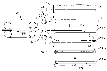
I S Figures 1 to 4 illustrate an exemplary embodiment of the method according
to the
invention on the basis of a very schematically depicted embodiment of the
device
according to the invention. The illustrated method is a stream conversion from
transverse conveyance to parallel conveyance. The illustrated device comprises
a
transverse conveyor 1 as supplying conveyor with a direction FQ of transverse
20 conveyance. The transverse conveyor 1 comprises a row of conveying
compartments
11 having lateral outlets 13 and being aligned transverse to the direction FQ
of
transverse conveyance. The device further comprises a parallel conveyor 2 as
removing conveyor, having a direction FP of parallel conveyance and being, for
example, a stationary pair of band conveyors with a stationary entrance 21 or
a
CA 02479787 2004-08-27
$ 35-109 CA
simple conveyor belt. Between the transverse conveyor 1 and the parallel
conveyor 2
a stationary alignment means 3 is oriented towards the entrance 21 of the
parallel
conveyor 2. The alignment means 3 comprises two alignment rollers 31 and 32 of
the
form already described further above. An auxiliary conveying .means (not
shown) is
assigned to each compartment 1 I of the transverse conveyor I, for example, a
slider
whose effect on the articles within the compartments 11 is illustrated by
arrows 12.
Figs. 1 to 4 show the device, for example, from above, in such a manner, that
the
direction FQ of transverse conveyance and the direction FP of parallel
conveyance
are situated in a horizontal plane and encompass an angle of 90°. If
the device
10 according to the invention is oriented in this manner, the conveying
compartments 11
of the transverse conveyor may be open on top and on both sides, in particular
if the
handled articles are relatively heavy and are held in the compartments by
gravity.
The auxiliary conveying means may comprise one slider in each one of the
compartments.
The mentioned device orientation, however, is not ~a prereguisite for the
method in
accordance with the invention. Figs. 1 to 4, for example, may also be
understood as
side views, wherein the direction FQ of transverse conveyance runs vertically
and the
direction FP of parallel conveyance runs horizontally. In this case, the sides
of the
conveying compartments 11 directed towards the viewer may need to be equipped
20 with suitable means for keeping the articles in the compartments. It is
also not a
prerequisite for the method according to the invention, that the angle between
the
direction FQ of transverse conveyance and the direction FP of parallel
conveyance is
a right angle. If this angle should differ from 90° the compartments 11
need to be
arranged relative to the direction of transverse conveyance such that the
conveying
direction of the auxiliary conveying means is still parallel to the direction
of parallel
conveyance.
CA 02479787 2004-08-27
g 35-109 CA
Figs. 1 to 4 illustrate the stream conversion according to the invention
essentially on
the basis of the transfer of article 5, which is supplied in the conveying
compartment
11.1 of the transverse conveyor and is delivered ao the parallel conveyor by
the
alignment means 3.
In Fig. l, the conveying compartment 11.1 containing article 5 is approaching
alignment with the entrance 21 of the parallel conveyor 2 and an edge 5.1 of
article 5
which is the leading edge in the direction FP of parallel conveyance has left
the
conveying compartment 11.1 and, driven by the auxiliary conveying means is
already moving into the action range of the alignment means 3. The
accelerating
effect of the auxiliary conveying means is visible from the positions of the
articles in
compartments 11.2 to 11.4 upstream of compartment 11.1.
Fig. 2 illustrates the moment, in which outlet 13 o:f compartment I1.1 is
precisely
aligned to the entrance 21 of the parallel conveyor. .At this moment the
article has a
speed corresponding to the speed of parallel conveyance and the alignment
means
starts to act on article 5 by gripping it in a clamping manner between the
leading
ends of the roller zones of constant maximum radius. From this moment, the
leading
edge of article 5 is precisely aligned to the entrance 21 of the parallel
conveyor 2 and
is guided into it by alignment means 3. After this moment, the trailing zone
of article
5 is bent by the relative movement of compartment 11.1 and alignment means 3.
20 Fig. 3 shows article 5 at a moment, at which its leading edge 5.1 is
already held
gripped in the parallel conveyor 2, at which the effect of the alignment means
3 on
the article 5 has ended but at which article 5 is still bent, namely between
the
entrance 21 of parallel conveyor 2 and the outlet 13 of compartment 11.1.
CA 02479787 2004-08-27
35-109 CA
Fig. 4 finally illustrates how article 5 disappears in to entrance 21 of the
parallel
conveyor 2 and how a further article supplied in the next compartment 11.2 is
moved
in to the action range of the alignment means 3 by the auxiliary conveying
means.
From Figs. 1 to 4 it is evident, that it is readily possible to supply two or
more than
5 two parallel conveyors with articles using one only transverse conveyor 1.
For such
purpose, the entrances of the parallel conveyors 2 h;~ve to be aligned to one
another
in parallel, for example at a distance, which corresponds to a whole multiple
of the
distance between compartments. The auxiliary conveying means of groups of
compartments 11 are then controlled in synchronism, every compartment of a
group
10 being assigned to one of the parallel conveyors.
Figs. S to 8 illustrate a stream conversion from parallel conveyance to
transverse
conveyance, using substantially the same device and the same method as shown
in
Figs. 1 to 4. The conveying directions FQ and FP and therewith the conveying
direction of the not shown auxiliary conveying means (arrows 12) point in
opposite
15 directions compared with Figs 1 to 4 and the alignment rollers 31 and 32
rotate in the
opposite direction. The auxiliary conveying means are e.g. designed as
grippers
being movable within the compartments 11 and gripping the articles by their
inner
edge (see also Fig. 12). "I'he alignment means 3 is aligned to the entrance
13' of the
conveying compartment 11.1, by which the article currently to be transferred
is to be
20 taken over, i.e., it is, at least during its acting on article 5, conveyed
together with the
compartment 11.1 in the direction of transverse conveyance.
Fig. 5 shows the emergence of the leading edge 5.1 of article 5 ti-om the
outlet 21' of
the parallel conveyor 2 and Fig. 6 shows the beginning of the action on the
leading
zone of article 5 by the alignment means 3, at the moment, in which the
entrance 13'
25 of the transverse conveyor 1 and together with it the alignment means 3 is
aligned to
CA 02479787 2004-08-27
11 35-109 CA
outlet 21' of parallel conveyor 2. Fig. 7 shows the ;article 5 bent between
the outlet
21' of parallel conveyor 2 and the entrance 13' of compartment 11.1 after the
end of
action by the alignment means 3. Fig. 8 illustrates the last part of the
pulling-in of
article 5 in to the compartment 11.1 and the emergence of a next article from
the
5 outlet 21' of parallel conveyor 2.
In the same manner as described further above for the method and the device
according to the Figs. 1 to 4, it is possible with the method and the device
in
accordance with Figs. 5 to 8 also to provide more than one parallel conveyor.
Figure 9 depicts an installation comprising a device 30 in accordance with the
10 invention, such as is illustrated, for example, in Figs. 1 to 4. The
installation serves
for producing in a continuous manner (e.g., by collating) stack-shaped groups
of
partial products and for glue-binding the partial products of every stack. The
installation is illustrated in Fig. 9 as a schematic view from above and in
Fig. 10 as a
three-dimensional partial view.
15 The installation comprises a collating stretch 10 for producing a stream of
stack-
shaped groups, the collating stretch comprising a plurality of feed points 20
arranged
one after another, wherein at each feed point one partial product is added to
each
stack. The product edges to be bound are the leading edges and within every
stack
they are already aligned to one another as accurately as possible.
20 The stack-shaped groups being supplied by the collating stretch, are
positioned in the
compartments 11 of the transverse conveyor 1 of the device according to the
invention in a per se known manner, by e.g. being pushed from a conveyor belt
into
the compartments 11, which being deviated have an approximately horizontal
CA 02479787 2004-08-27
12 35-109 CA
position or a position being slightly declining towards the inside. The stack-
like
groups may also be introduced from above into the compartments being conveyed
essentially horizontally. In the compartments the stack edges to be bound are
facing
towards the inside, i.e. downwards. From the compartments 11, the stack-shaped
5 groups are transferred to the parallel conveyor 2 in the manner described in
conjunction with Figs. 1 to 4, to be conveyed in to the glue-binding machine
40 and
having an orientation suitable for glue-binding (edge to be bound facing
downwards
and being aligned in conveying direction).
During conveyance in the compartments 1 l, alignment of the part product edges
to
10 be bound may be improved by vibrating the compartments or the part products
may
be laterally aligned in any known manner. Equally during conveyance in the
compartments - before they reach the entrance of the parallel conveyor - stack
thickness may be measured and auxiliary conveying means in compartments
containing too thin or too thick and therefore faulty stacks may not be
activated such
15 preventing faulty stacks from being conveyed in to the binding machine but
being
conveyed on and being e.g. during the next deviation of the conveying
compartments
1 l to be dropped from the compartment.
Fig. 10 is a three-dimensional illustration of the one part of the
installation according
to Fig. 9, which comprises device 30 according to the invention. Same elements
are
20 designated with same reference numbers as in previous Figs. From Fig. 10 it
is
evident, that the transverse conveyor 1 is designed as a circulating system
with two
deflection rollers. The compartments 11 protruding in radial direction, for
example,
are attached to two chains circulating in parallel, wherein the chains run
over the
deflection rollers.
CA 02479787 2004-08-27
13 35-109 CA
For stacks having a binding edge with a length of 425 mm, as is the case for
magazines, and for a compartment spacing in the transverse conveyor 1 of 8 cm,
for
achieving a capacity of 15'000 copies per hour, a speed of transverse
conveyance of
0,34 m/s and a speed of parallel conveyance of 1,7 m~/s are required. For a
capacity of
5 18'000 copies per hours, the speeds are correspondingly 0,42 and 2,13 m/s.
It is particularly advantageous, if for producing the stack-shaped groups the
method
described in the patent application WO-03/053831 is used, i.e. the groups are
produced not by collating, but rather by guiding imbricated streams of
different part
products to be superimposed. The part products in all imbricated streams are
10 arranged in such a manner, that leading edges of the part products of each
group are
aligned to one another. From the leading end of the superimposed imbricated
streams
the groups are separated in succession by gripping the aligned part product
edges
and are advantageously directly transferred in to compartments 11 of the
transverse
conveyor 1.
15 Figure 11 shows in more detail an exemplary embodiment of conveying
compartments 11 for a transverse conveyor 1 as shown in the preceding Figs.
Each
conveying compartment I 1 comprises an upstream wall 51 being rigidly
connected
to a compartment floor 50 and a downstream wall 5:Z being pivotally supported
in the
compartment floor. The downstream wall 52 is held in a closed position by a
not
20 illustrated resetting means and it is brought into an open position
controlled, for
example, by a earn 53, on which a control roller 54 arranged at the lower end
of the
downstream wall 52 rolls. The compartments are arranged on a circulating
conveying
organ, e.g., chains (dot-dash Line 55), in such a manner that they follow one
behind
the other as closely as possible when being conveyed along a straight path and
that
25 they are capable of being opened sufficiently for introduction of the flat
articles 5 or
of the stack-shaped groups of part products in the area of the deflection
wheel 56.
CA 02479787 2004-08-27
14 35-109 CA
Fig 11 shows an auxiliary conveying means in the form of a slider 60 being
provided
in each one of the compartments 1 I . The slider 60 protrudes in to the
compartment
1 I through a corresponding slit in the upstream wall 51 and is supported
outside of
the upstream wall 51 by a longitudinal guide system 61. The slider movement
5 parallel to the axis of the deflection wheel 56 is co~atrolled by a not
shown cam, on
which control rollers 62 installed on the slider roll.
For an adjustment of the compartments 11 to the thickness of the articles 5 or
the
stacks to be processed, it is advantageous to design the pivoting support of
the
downstream walls 52 to be displaceable in such a manner, that the width of the
10 compartment floor 50 becomes adjustable.
It is also possible to provide an external slider or an arrangement of a
plurality of
external sliders instead of the sliders according to Fig. I I which are
arranged within
every compartment 11 and to move the external slider into the compartments in
a
direction oblique to the direction of transverse conveyance. Such auxiliary
conveying
15 means is, for example, described in the publication US-1760030 mentioned
further
above.
Figure 12 illustrates a further, exemplary embodiment of an auxiliary
conveying
means for a conveying compartment 11 of a transvf.rse conveyor in accordance
with
the invention. The conveying compartment 1 I which has no upstream wall is
viewed
20 perpendicular to the direction of transverse conveyance. The auxiliary
conveying
means comprises two jaw-like clamping parts 70 (one of them visible) being
mounted on a slide 71 and being movable against each other and away from each
other. Slide 71 is arranged near the compartment floor 50 and is displaceable
transverse to the direction of transverse conveyance. The slide movement is
CA 02479787 2004-08-27
15 35-109 CA
controlled, for example, by a cam 73, on which a control roller 74 arranged on
a slide
part protruding from the compartment 11 rolls.