Note : Les descriptions sont présentées dans la langue officielle dans laquelle elles ont été soumises.
CA 02480469 2004-09-27
WO 03/079956 PCT/SE03/00405
1
Title
Fluid transfer assembly
Technical field
The present invention relates to a fluid transfer assembly for use in an
infusion
system, including a fluid container containing an infusion fluid, and a drug
container
containing a medical substance, wherein the fluid container has at least one
inlet port
for receiving the medical substance from the drug container and the assembly
further
includes at least one fluid barrier controlling fluid passage between the drug
container
and the fluid container. The invention also relates to a drug container for
use in the
infusion system, and to a method for enabling fluid transfer in the infusion
system.
Background of the invention
A serious problem in connection with drug preparation, drug administration and
other
similar handling is the risk that medical and pharmacological staff are
exposed to
drugs or solvents which might escape into the ambient air. This problem is
particularly serious when cytotoxins, antiviral drugs, antibiotics and
radiopharmaceuticals are concerned.
For this reason, there has been a need of safer systems for handling and
administrating drugs and other medical substances.
Accordingly, U.S. Patent No. 4,564,054 discloses a fluid transfer device for
transferring a substance from one vessel to another vessel avoiding leakage of
liquid
and gas contaminants. The disclosed device comprises a first member designed
as a
hollow sleeve and having a piercing member provided with a passageway. The
piercing member is attached to the first member which has a first barrier
member at
one end just opposite the tip of the piercing member. Thereby, the piercing
member
can be passed and retracted through the first barrier member which seals one
end of
the first member. The fluid transfer device further comprises a second member
which
is attached to or attachable to one of the vessels or to means arranged to
communicate therewith. The second member has a second barrier member, and
mating connection means arranged on the first and second members for providing
a
CA 02480469 2004-09-27
WO 03/079956 PCT/SE03/00405
2
releasable locking of the members with respect to each other. The barrier
members
are liquid and gas-proof sealing members which seal tightly after penetration
and
retraction of the piercing member and prevent leakage of liquid as well as gas
contaminants. In the connected position of the first and second members, the
barrier
members are located in such a way with respect to each other that the piercing
member can be passed therethrough.
According to US 4,564,054, the above-mentioned piercing member is a needle
arranged for puncturing the first and the second barrier members, wherein the
end
opposite to the one end of the first member lids means for sealingly receiving
ol
being permanently attached to an injection syringe or the like for withdrawing
and/or
adding substance to the vessel attached to the second member. When attached to
the first member, the injection syringe or the like communicates with the
passageway
of the needle, so that in the retracted position the needle is hermetically
enclosed in
the first member having the injection syringe or the like connected thereto.
The international patent publication No. WO 99/27886 (Fowles et. al) discloses
a
connector device intended for establishing fluid communication between a first
container and a second container. The connector device comprises a first
sleeve
member having a first and a second end, wherein the first sleeve member has a
first
attaching member at the first end which is adapted to attach to the first
container.
The connector device further comprises a second sleeve member which has a
first
end and a second end. Thereby, the second sleeve member is associated to the
first
sleeve member and movable with respect thereto from an inactivated position to
an
activated position, wherein the second sleeve member has a second attaching
member at the second end adapted to attach the second sleeve member to the
second container. According to WO 99/27886, the connector device further
comprises
a first and second piercing member projecting from one of the first and second
sleeve
members for providing a fluid flow path from the first container to the second
container, and means for independently hermetically sealing the first and
second
members.
Furthermore, U.S. Patent No. 6,258,078 B1 discloses a luer connector which
facilitates connection of a hypodermic syringe to a vial, comprising a luer
connectable
to a syringe and which extends to a sharpened end capable of being driven
through a
puncturable vial closure to thereby puncture the closure, a luer support
mountable on
a vial, and which initially supports the luer in a first position in which the
sharpened
CA 02480469 2009-10-15
3
end of the conduit is pointed towards the closure, and a luer driver such that
movement of the driver relative to the support causes the luer to be driven so
that the
sharpened end punctures the closure and enters the vial.
When performing infusion, it is often necessary to inject a drug or other
medical
substance into the infusion fluid inside an infusion bag or other infusion
fluid
container. This is normally done by means of penetrating a septum or another
fluid
barrier of an injection port on the infusion bag or the infusion fluid line
with a
hypodermic needle of a syringe filled with the medical fluid in question.
However, it has been found that the use of regular syringes or other drug
containers
according to prior art when injecting hazardous substances such as cytotoxins
into
an infusion bag or another infusion fluid container might cause pollution of
the
working environment, something which of course is unacceptable. For this
reason,
there is a need of an improved device which eliminates the risk that
potentially
health-hazardous substances escape into the ambient air or working environment
when injecting a drug or another medical substance into an infusion system.
Furthermore, there is a strong need of reducing the costs for medical
treatment such
as infusion treatment. One way of reducing the costs would be to reduce the
number
of medical device components which are needed for introducing medical
substances
into the infusion system, and which have to be kept in stock at hospitals
which
perform such infusion treatment.
Summary of the invention
Accordingly, a first object of the present invention is to provide a very
simple, reliable
and safe fluid transfer assembly for use in an infusion system, which assembly
allows
the administration of a medical substance to a patient using a minimum of
medical
device components.
This first object is achieved by means of a fluid transfer assembly including
a fluid
container containing an infusion fluid, and a drug container containing a
medical
substance, wherein the fluid container has at least one inlet port for
receiving the
medical substance from the drug container, and the assembly further includes
at
least one fluid barrier controlling fluid passage between the drug container
and the
fluid container. Thereby, the inlet port exhibits a first luer-lock connector,
and the
drug container is sealed by a cap exhibiting a second luer-lock connector for
CA 02480469 2009-10-15
4
attachment to the first luer-lock connector, wherein the fluid barrier is
designed and
arranged to be ruptured by an external force to allow the fluid passage.
A second object of the present invention is to provide a drug container for
use in the
assembly according to the invention.
This second object is achieved by means of a drug container containing a fixed
dose
of a medical substance, wherein the drug container is sealed by a cap
exhibiting a
luer-lock connector for attachment to a corresponding connector provided on an
inlet
port of a container for infusion fluid in order to create a luer-lock
coupling.
A third object of the present invention is to provide a method for enabling
fluid
transfer in an infusion system including the assembly according to the
invention.
This third object is achieved by means of a method which includes to provide a
fluid
container containing an infusion fluid and a drug container containing a
medical
substance, wherein the fluid container has at least one inlet port for
receiving the
medical substance from the drug container, and the method further includes to
provide the infusion system with at least one fluid barrier controlling fluid
passage
between the drug container and the fluid container. Thereby, the method
further
includes to provide the fluid container with a first luer-lock connector on
the inlet port,
to provide the drug container with a cap exhibiting a second luer-lock
connector, and
to attach the first luer-lock connector to the second luer-lock connector by
means of a
luer-lock coupling. Furthermore, the method includes to apply an external
force onto
said fluid barrier to open the fluid passage, to create a positive pressure
inside the
fluid container, to transfer at least part of the positive pressure to the
drug container
via the fluid passage, and to remove the positive pressure from the fluid
container in
order to initiate transfer of the medical substance from the drug container to
the fluid
container.
Further objects of the present invention will become evident from the
following
description, and the features enabling these further objects to be achieved
are listed
in the dependent claims.
CA 02480469 2004-09-27
WO 03/079956 PCT/SE03/00405
Brief description of drawings
In the following, the present invention will be described in greater detail
with
reference to the attached drawings, in which
5
Fig. 1 is a schematic perspective view illustrating both a preferred
embodiment and
an alternative embodiment of a fluid transfer assembly according to the
invention,
Fig. 2 is a schematic perspective view of a drug container according to a
preferred
i0 embodiment of the invention,
Fig. 3 is a schematic perspective view of a drug container according to an
alternative
embodiment of the invention,
Fig. 4 is a schematic perspective view of a drug container according to
another
alternative embodiment of the invention, and
Fig. 5 is schematic perspective view of an alternative embodiment of a fluid
transfer
assembly according to the invention.
Detailed description of preferred embodiments
In the following, a preferred embodiment and a number of alternative
embodiments
of the assembly according to the invention will be described in greater detail
with
reference to the attached Figs. 1 - 5.
The fluid transfer assembly according to the invention is intended for use in
an
infusion system of the type where it might become necessary to introduce a
medical
substance, such as a drug, cytotoxin or an antibiotic, into an infusion fluid,
such as a
saline solution.
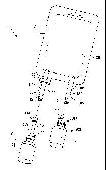
As is evident from Fig. 1, the assembly 100 includes a fluid container 101
containing
an infusion fluid 102 and a drug container 103; 203 containing a medical
substance
104; 204.
Preferably, the fluid container 101 is a flexible bag made of a plastic film
which
exhibits suitable properties for the application. The fluid container 101 has
at least
one inlet port 105; 106 for receiving the medical substance 104; 204 from the
drug
CA 02480469 2004-09-27
WO 03/079956 PCT/SE03/00405
6
container 103; 203. The assembly further includes at least one fluid barrier
107; 108
controlling fluid passage between the drug container 103; 203 and the fluid
container
101.
It should be noted that Fig. 1 illustrates both a preferred (e.g. reference
numerals
101, 105 and 103) and an alternative embodiment (e.g. reference numerals 101,
106
and 203) of the fluid transfer assembly according to the invention.
Accordingly, in
real life, only one of the ports, e.g. the one denoted 105, would act as an
inlet port
for receiving the medical substance from the drug container 103, whereas the
other
port 106 wouiu act as an outlet port for a mixture of the infusion fluid and
the
introduced medical substance. Alternatively, the port denoted 106 in Fig. 1
could act
as an inlet port for medical substance from the drug container 203, while the
port
denoted 105 could act as an outlet port to which an infusion line can be
connected.
Different types of inlet ports are known per se. An inlet port according to
prior art
usually exhibits a septum acting as a fluid barrier. Such a septum according
to prior
art is intended to be penetrated by a piercing member such as a hypodermic
needle
of a syringe containing the medical substance which is to be administrated.
According to the invention, however, the inlet port 105; 106 exhibits a first
luer-lock
connector 110; 111. The function of male/female luer-lock connectors is well
known
per se, but for other uses than in the assembly according to the invention.
According to the invention, the drug container 103; 203 is sealed by a cap
112; 212
exhibiting a second luer-lock connector 113; 213 for attachment to the first
luer-lock
connector 110; 111. This feature of the present invention enables the drug
container
103; 203 to be attached to the infusion fluid container 101 in a very simple,
fast and
safe way.
Furthermore, according to the invention, the fluid barrier 107, 109; 108 is
designed
and arranged to be ruptured by an external force to allow the fluid passage
from the
drug container to the fluid container, or vice versa. This feature ensures
that no
premature fluid communication takes place between the drug container and the
fluid
container.
In one advantageous embodiment of the fluid transfer assembly according to the
invention, the inlet port 105; 106 forms a first fluid duct between the fluid
container
CA 02480469 2004-09-27
WO 03/079956 PCT/SE03/00405
7
101 and the first luer-lock connector 110; 111, wherein the fluid barrier 107;
108 is
provided inside this first fluid duct.
In another advantageous embodiment, the cap 112 of the drug container 103
exhibits a protruding member 114 which forms a second fluid duct between the
drug
container 103 and the second luer-lock connector 113, wherein the fluid
barrier 109
is provided inside the second fluid duct.
In a preferred embodiment of the assembly according to the invention, the
inlet port
105 forms a first fluid duct between the fluid container 101 and the first
luer-lock
connector 110. Furthermore, the cap 112 exhibits a protruding member 114 which
forms a second fluid duct between the drug container 103 and the second luer-
lock
connector 113, wherein fluid barriers 107; 109 are provided both inside the
first and
the second fluid ducts. This feature provide full control over the fluid
communication
between the drug container and fluid container, and ensures that no accidental
fluid
transfer can take place.
In an alternative embodiment of the fluid transfer assembly according to the
invention, the second luer-lock connector 213 is attached directly to the cap
212.
Even more advantageously, as illustrated in Fig. 3, the second luer-lock
connector
213 is an integrated portion of the cap 212. In order to prevent
contamination, as
indicated in Fig. 2, and in the embodiment in Fig. 3 also in order to seal the
drug
container, the second luer-lock connector 113; 213 preferably is protected by
a
removable closure 126; 226 or a protective lid, or alternatively a pierceable
closure,
before use.
In the alternative embodiment of the assembly, the drug container 203
preferably
exhibits a neck 215, as indicated in Fig. 3, wherein the cap 212 exhibits
locking
members 216 for grasping the neck 215. Even more advantageously, the drug
container also exhibits an opening sealed by a closure 217, wherein the cap
212
exhibits a hollow needle 218 for penetrating the closure 217. The alternative
embodiment enables the use of conventional drug vials in the assembly
according to
the invention, something which might be advantageous for practical reasons.
In the preferred embodiment of the fluid transfer assembly, as shown in Figs.
1 and
2, the drug container 103 exhibits a neck 115, wherein the cap 112 exhibits a
protruding member 114 which is attached to the neck 115 by means of an annular
CA 02480469 2004-09-27
WO 03/079956 PCT/SE03/00405
8
capsule member 121. The capsule-like attachment makes it possible modify a
fairly
conventional drug vial-filling line to produce drug containers for use in the
fluid
transfer assembly according to the invention. However, within the scope of the
invention, it is also conceivable with embodiments where a protruding member
is
attached to the drug container by means of another suitable permanent
attachment.
In another advantageous embodiment of the fluid transfer assembly according to
the
invention, as illustrated in Fig. 4, the drug container 303 exhibits a neck
315, and the
cap 312 exhibits a protruding member 314 which forms a second fluid duct
between
the drug container 303 and the second luer-lock connector 313. In this
embodiment
the cap 312 further exhibits locking members 316 for grasping the neck 315.
Thereby, the locking members 316 enable also drug vials of a conventional
design to
be used in the fluid transfer assembly, whereas the protruding member 314
makes it
easier to control the fluid passage between the fluid container in question
and the
drug container 303, or vice versa.
In the preferred embodiment of the fluid transfer assembly, as indicated in
Figs. 1
and 2, the fluid barrier is constituted of a brittle polymer member 107, 109;
108
which can be divided along a weakening line by means of said external force.
However, within the scope of the invention, it is conceivable with many
different
designs of the fluid barrier, as long as the barrier provides a safe sealing
of the fluid
container and/or the drug container, and as long as it is possible for an
operator to
eliminate the sealing action by means of applying an external force onto the
fluid
barrier in order to break, rupture, puncture, or dislocate the fluid barrier
and open a
fluid passage through the barrier.
In another embodiment of the fluid transfer assembly, walls 119 of the inlet
port 105
are made of a flexible material and form a first fluid duct between the fluid
container
101 and the first luer-lock connector 110. In this embodiment, in order to
provide an
improved control of the fluid passage, the fluid transfer assembly 100 further
includes a first clamping member 127 for compressing the walls 119 in order to
close
the first fluid duct and prevent undesired fluid passage between the fluid
container
101 and the first luer-lock connector 110. This embodiment is particularly
valuable
after having transferred the entire fixed dose of medical substance from the
drug
container inro the infusion fluid container, since it prevents fluid from
returning into
the drug container.
CA 02480469 2004-09-27
WO 03/079956 PCT/SE03/00405
9
Alternatively, as illustrated in Fig. 5, the cap 312 of the drug container
exhibits a
protruding member 314 which forms a second fluid duct between the drug
container
303 and the second luer-lock connector 313, wherein the fluid transfer
assembly 300
includes a second clamping member 328 for compressing the protruding member
314
in order to close the second fluid duct and prevent undesired fluid passage
between
the second luer-lock connector 313 and the drug container 303.
In another alternative embodiment, as illustrated in Fig. 5, the fluid
container 301
exhibits a protruding, resilient tube 322, wherein the first luer-lock
connector 310 of
1G the inlet port 305 is provided on a hollow spike member 323 designed and
arranged
to be firmly retained inside the tube 322. This embodiment enables
conventional
infusion bags to be utilised in the fluid transfer assembly according to the
invention.
In still another alternative embodiment of the fluid transfer assembly, in
addition to
the first luer-lock connector 310, the inlet port 305 also exhibits an
infusion line 325
attached thereto, wherein the fluid transfer assembly 300 includes a third
clamping
member 329 for compressing the infusion line 325 in order to prevent undesired
fluid
passage therethrough. This embodiment makes it possible to prevent accidental
passage of medical substance into the infusion line while transferring the
medical
substance from the drug container into the infusion fluid container.
In the preferred embodiment of the fluid transfer assembly according to the
invention, the inlet port 105; 106 forms a first fluid duct between the fluid
container
101 and the first luer-lock connector 110; 111, wherein the fluid barrier 107;
108 is
provided inside the first fluid duct. Furthermore, the fluid container 101 is
flexible and
made of a first polymer material, the first fluid duct is formed by walls 119;
120
made of a second polymer material, the first luer-lock connector 110; 111 is
made of
a third polymer material, and the fluid barrier 107; 108 is made of a fourth
polymer
material. Thereby, the first 101 and second 119; 120 polymer materials are
more
flexible than the third 110; 111 polymer material, and the fourth polymer
material
107; 108 is more brittle than all of the first 101, second 119; 120 and third
110; 111
polymer materials. This preferred choice of materials ensures that the action
of the
fluid barrier 107 (and 108) between the fluid container and the first luer-
lock
connector can be eliminated without accidentally breaking other components of
the
fluid transfer assembly according to the invention.
CA 02480469 2004-09-27
WO 03/079956 PCT/SE03/00405
In the preferred embodiment, the cap 112 exhibits a protruding member 114
which
forms a second fluid duct between the drug container 103 and the second luer-
lock
connector 113, wherein the fluid barrier 109 is provided inside the second
fluid duct.
Thereby, the drug container 103 is made of a rigid material, the protruding
member
5 114 is made of a more flexible material than the second luer-lock connector
113 and
the drug container 103, and the fluid barrier 109 is made of a more brittle
material
than the drug container 103, the protruding portion 114, and the second-luer
lock
connector 113. In a corresponding way as described above, this preferred
choice of
materials ensures that the fluid barrier 109 between the drug container and
the
10 second suer-lock connector can be eliminated without accidentally breaking
any othe
components of the fluid transfer assembly according to the invention.
In the preferred embodiment of the fluid transfer according to the invention,
the drug
container 103; 203 is made of glass. However, within the scope of the
invention, it
also conceivable with embodiments where the drug container is made of another
suitable material, e.g. a rigid polymer material, as long as the material has
a
sufficient chemical resistance and otherwise is suitable from a medical point
of view.
In the following, a preferred embodiment and a number of alternative
embodiments
of a drug container according to the invention will be described in greater
detail with
particular reference to Figs. 2, 3 and 4.
The drug container is intended for use in an infusion system including a fluid
transfer
assembly according to the invention.
The drug container 103; 203; 303 contains a fixed dose of a medical substance
104;
204; 304. In this context, "fixed dose" means that the quantity of medical
substance
is intended to be transferred to the infusion fluid container in question in
its entirety,
and that a drug container containing the desired quantity of medical substance
has to
be selected before administration. The medical substance can be provided
either in a
fluid state, or advantageously in the form of a dry powder which is dissolved
into a
small quantity of infusion fluid from the fluid container connected to the
drug
container in order to form a drug solution which is returned to the infusion
fluid
container.
According to the invention, the drug container 103; 203; 303 is sealed by a
cap 112;
212; 312 exhibiting a luer-lock connector 113; 213; 313 for attachment to a
CA 02480469 2004-09-27
WO 03/079956 PCT/SE03/00405
11
corresponding connector provided on an inlet port of a container for infusion
fluid in
order to create a luer-lock coupling. This feature enables the drug container
to be
utilised in a fluid transfer assembly according to the invention. The luer-
lock
connector of the drug container will be a male luer-lock connector when it is
intended
to interact with an inlet port of a fluid container provided with a female
luer-lock
connector. In case the drug container is intended to interact with an inlet
port
exhibiting a male luer-lock connector, it will of course have to exhibit a
female luer-
lock connector.
In the preferred embodime. it of the drug container, the cap 112 exhibits a
protruding
member 114 which forms a fluid duct between the drug container 103 and the
second luer-lock connector 113, wherein a fluid barrier 109 which is designed
and
arranged to be ruptured by means of an external force is provided inside the
second
fluid duct. Preferably, the fluid barrier is designed and arranged to be
ruptured by
means of an external force exerted by a person by hand. This is also the case
with
the other fluid barriers included in the fluid transfer assembly according to
the
invention.
In the preferred embodiment, the drug container 103 exhibits a neck 115,
wherein
the cap 112 exhibits a protruding member 114 which is attached to the neck 115
by
means of an annular capsule member 121. However, as mentioned above, it is
also
conceivable with embodiments where the protruding member is permanently
attached to the drug container in another suitable way.
In another advantageous embodiment, as illustrated in Fig. 4, the drug
container 303
exhibits a neck 315, and the cap 312 exhibits a protruding member 314 which
forms
a second fluid duct between the drug container 303 and the second luer-lock
connector 313, wherein the cap 312 further exhibits locking members 316 for
grasping the neck 315. This embodiment enables the cap to be permanently
attached
to a drug vial of a conventional design. Furthermore, the protruding member
improves the possibilities to control the fluid passage out from or into the
drug
container, since a suitable fluid barrier can be arranged inside said second
fluid duct,
or the second fluid duct can be blocked or opened by means of applying or
removing
an external pressure, e.g. as indicated in Fig. 5 by means of a suitable
clamping
member 328 of a type which is wellknown per se.
CA 02480469 2004-09-27
WO 03/079956 PCT/SE03/00405
12
In the preferred embodiment of the drug container, as indicated in Fig. 2, the
protruding member 114 encircles a fluid barrier constituted of a brittle
polymer
member 109 which can be divided along a weakening line by means of an external
force.
In the preferred embodiment, the protruding member 114 forms a fluid duct
between
the drug container 103 and the luer-lock connector 113, wherein the fluid
barrier 109
is provided inside the fluid duct. Thereby, the drug container 103 is made of
a rigid
material, the protruding member 114 is made of a more flexible material than
the
suer-lock connector 113 and the drug container 103, and the fluid bai rier 109
is made
of a more brittle material than the drug container 103, the protruding portion
114,
and the luer-lock connector 113.
In an alternative embodiment of the drug container according to the invention,
as
illustrated in Fig. 3, the luer-lock connector 213 is attached directly to the
cap 212.
Advantageously, the luer-lock connector 213 is an integrated portion of the
cap 212.
Thereby, the second luer-lock connector 213 preferably is protected by a
removable
or pierceable closure 226.
In the alternative embodiment, the drug container 203 advantageously exhibits
a
neck 215, wherein the cap 212 exhibits locking members 216 for grasping the
neck
215. Even more advantageously, the drug container 203 in the alternative
embodiment exhibits an opening sealed by a closure 217, wherein the cap 212
exhibits a hollow needle 218 for penetrating the closure 217.
Preferably, the drug container 103; 203 according to the invention is made of
glass.
However, it is also conceivable with embodiments where the drug container is
made
of another material, e.g. a suitable rigid polymer material.
In the following, a preferred embodiment and a number of alternative
embodiment of
a method according to the invention will be described in greater detail,
whenever
applicable with reference to the attached Figs. 1 - 5.
The method is intended for enabling fluid transfer in an infusion system
utilising the
fluid transfer assembly according to the invention.
CA 02480469 2004-09-27
WO 03/079956 PCT/SE03/00405
13
The method includes to provide a fluid container 101 containing an infusion
fluid 102
and a drug container 103; 203 containing a medical substance 104; 204.
Thereby,
the fluid container 101 has at least one inlet port 105; 106 for receiving the
medical
substance 104; 204 from the drug container 103; 203. The method further
includes
to provide the infusion system with at least one fluid barrier 107; 108
controlling fluid
passage between the drug container 103; 203 and the fluid container 101.
The method according to the invention further includes to provide the fluid
container
101 with a first luer-lock connector 110; 111 on the inlet port 105; 106, to
provide
the drug container 103; 203 with a cap 112; 212 exhibiting a second luer-lock
connector 113; 213, to attach the first luer-lock connector 110; 111 to the
second
luer-lock connector 113; 213 by means of a luer-lock coupling, to apply an
external
force onto the fluid barrier 107, 109; 108 to open the fluid passage, and to
create a
positive pressure inside the fluid container 101. According to the invention
the
method also includes to transfer at least part of the positive pressure to the
drug
container 103; 203 via the fluid passage, and to remove the positive pressure
from
the fluid container 101 in order to initiate transfer of the medical substance
104; 204
from the drug container 103; 203 to the fluid container 101.
In a preferred embodiment, the method further includes to rupture the fluid
barrier
107; 108 by means of twisting, bending, or squeezing material portions 119;
120
between the fluid container 101 and the first luer-lock connector 110; 111.
Preferably, the method also includes to rupture another fluid barrier by means
of
twisting, bending or squeezing material portions 114 between the drug
container 103
and the second luer-lock connector 113.
Particularly advantageously, the method further includes to provide the drug
container 103 exhibiting a neck 115, to provide the cap 112 exhibiting a
protruding
member 114, to provide an annular capsule member 121, and to attach the
protruding member 114 to the neck 115 by means of the annular capsule member
121 in a drug container filling line.
Preferably, the method further includes to provide the fluid barrier in the
form of a
brittle polymer member 107,109; 108 exhibiting at least one weakening line,
and to
divide the brittle polymer member 107,109; 108 along the weakening line by
means
of the external force.
CA 02480469 2004-09-27
WO 03/079956 PCT/SE03/00405
14
In the preferred embodiment, the method further includes to make the fluid
container 101 of a flexible first polymer material, to form walls 119; 120 of
a second
polymer material into a first fluid duct between the fluid container 101 and
the first
luer-lock connector 110; 11, to make the first luer-lock connector 110; 111 of
a third
polymer material, and to make the fluid barrier 107; 108 of a fourth polymer
material. Thereby, the method further includes to arrange the fluid barrier
107; 108
inside the first fluid duct, to select the first 101 and second 119; 120
polymer
materials to be more flexible than the third 110; 111 polymer material, and to
select
the fourth polymer iiMaterial 107; 108 to be more brittle than all of the
first 101,
second 119; 120 and third 110; 111 polymer materials.
Preferably, the method further includes to make the drug container 103 of a
rigid
material, to include a protruding member 114 on the cap 112 in order to form a
second fluid duct between the drug container 103 and the second luer-lock
connector
113, and to accommodate the fluid barrier 109 inside the second fluid duct.
Thereby,
the method also includes to select a more flexible material for the protruding
member
114 than for the second luer-lock connector 113 and the drug container 103,
and to
select a more brittle material for the fluid barrier 109 than for the drug
container
103, the protruding portion 114, and the second luer-lock connector 113.
In an alternative embodiment of the invention, the method further includes to
provide the drug container 203 exhibiting a neck 215, to provide the cap 212
exhibiting locking members 216, and to cause the locking members 216 to grasp
said
neck 215 in order to attach the cap 212 permanently to the drug container 203.
In the alternative embodiment, the method advantageously also includes to
provide
the drug container 203 exhibiting an opening sealed by a closure 217, to
provide said
cap 212 exhibiting a hollow needle 218; and to cause the hollow needle 218 to
penetrate the closure 217.
Preferably, the method further includes to protect the second luer-lock
connector 213
by means of a removable closure 226, and to remove the closure before
attaching
the second luer-lock connector 213 to the first luer-lock connector 111.
Alternatively,
the method further includes to protect the second luer-lock connector 213 by
means
of a pierceable closure 226, and to pierce the closure 226 when attaching the
second
luer-lock connector 213 to the first luer-lock connector 111, something which
of
CA 02480469 2004-09-27
WO 03/079956 PCT/SE03/00405
course requires that the pierceable closure is made of material which will not
release
any loose particles into the luer-lock coupling or the fluid passage. The
skilled person
having read this description, however, should be able to find a suitable
material
without any extensive work.
5
The method according to the invention preferably also includes to make the
drug
container 103; 203 of glass or a rigid polymer material.
As used herein, the expression "drug container" refers to a container for
medical
10 substance which is leakage-proof and otherwise suitable for the purpose in
question.
Preferably, the "drug container" utilised in the assembly according to the
invention
has only one opening which is sealed by a closure or cap, and is made of a
solid, rigid
and inflexible material, such as glass or rigid polymer material. Furthermore,
it is
preferred that the drug container has no displaceable bottom, flexible walls,
or the
15 like, which will prevent the creation of the positive pressure which is
needed in order
to empty the medical substance into the infusion fluid in the interacting
fluid
container.
As used herein, the expression "permanent attachment" means that the
components
in question, in their normal, intended use, cannot be disengaged without the
use of
excessive force.
In the foregoing description, the present invention has been described in
connection
with a few specific embodiments and with reference to the attached drawings.
However, the present invention is by no means strictly confined to these
embodiments or to what is shown in the drawings, but the scope of the
invention is
defined in the following claims.
Accordingly, as illustrated in Fig. 1, the method according to the invention
can further
include to make the walls 119 of said inlet port 105 of a flexible material,
to form a
first fluid duct between the fluid container 101 and the first luer-lock
connector 110
inside the flexible material, and to provide a first clamping member 127 to
compress
the walls 119 in order to close the first fluid duct and prevent undesired
fluid passage
between the fluid container 101 and the first luer-lock connector 110.
In still another embodiment, illustrated in Fig. 5, the method can include to
provide
the cap 312 exhibiting a protruding member 314 which forms a second fluid duct
CA 02480469 2004-09-27
WO 03/079956 PCT/SE03/00405
16
between the drug container 303 and the second luer-lock connector 313, and to
provide a second clamping member 328 to compress the protruding member 314 in
order to close the second fluid duct and prevent undesired fluid passage
between the
second luer-lock connector 313 and the drug container 303.
Furthermore, the method can also include to provide the fluid container 301
exhibiting a protruding, resilient tube 322, to provide a hollow spike member
323
exhibiting the first luer-lock connector 310,and to insert the hollow spike
member
323 into the resilient tube 322, and/or to attach an infusion line 325 to the
inlet port
lu 305, in addition to the first luer- lock connector 310, and to provide a
third clamping
member 329 to compress the infusion line 325 in order to prevent undesired
fluid
passage therethrough.