Note : Les descriptions sont présentées dans la langue officielle dans laquelle elles ont été soumises.
CA 02480746 2004-09-07
DOUBLE ACTING CAM DIE
BACKGROUND OF THE INVENTION
The present invention relates to a double.acting cam
die which can process in different processing directions by
using a first processing member and a second processing
member.
A press dying includes a drawing process in a first
step, a trimming process in a second step, a piercing
process in a specific direction in a third step, a piercing
process in a different specific direction from the specific
direction in a fourth step, and the like.
Even in the same piercing process, if multiple
processing directions are required, to date it has not been
possible to process in different directions in the same
step.
Further, in known press dying methods, the number of
constituting parts of a die required for all the steps of
the press dying is fixed. In a process having an angle of
incline, three members comprising a slide cam base, a slide
cam and an actuating cam are required as the constituting
parts.
Further, each time the angle of incline for the
processing is different, a new design is required.
As stated above, if multiple processing directions are
required, to date it has not been possible to process in
different directions in the same process. Accordingly, it
1
CA 02480746 2004-09-07
would be desirable to execute processes having different
processing directions in the same step.
Further, in a process having an angle of incline, since
three members comprising the slide cam base, the slide cam
and the actuating cam are required as the constituent parts,
it would be desirable to reduce the number of the
constituent parts of the die required for all the steps of "
the press dying.
Further, since a new design is required each time the
angle of incline for the processing is different, it would
be desirable to be able to easily change a design and to
easily adjust the die to a design change.
Accordingly, in view of the desired features noted
above in accordance with the present invention, there is
provided a double acting cam die comprising a slide cam
base, a slide cam which is guided by the slide cam base and
which has a first processing member, such as a punch or the
like, mounted thereto, an energizing body (biasing member)
which is interposed between the slide cam base and the slide
cam so as to energize (bias) the slide cam, an actuating cam
which is brought into contact with the slide cam base and
the slide cam so as to drive the slide cam, and which has a
second processing member, such as a punch or the like,
mounted thereto, a guiding member which guides the actuating
cam, and a biasing member which is interposed between: the
guiding member and the actuating cam so as to bias the
actuating cam, wherein an angle of processing incline of the
2
CA 02480746 2004-09-07
second processing member is brought into line with an angle
of cam incline of the slide cam base.
Further, in accordance with a specific aspect of the
present invention, there is provided a double acting cam
die, wherein the actuating cam is hung from the guiding
member and is slidably provided thereon.
Further, in accordance with a specific aspect of the
present invention, there is provided a double acting cam
die, wherein a wear plate is provided on each sliding
surface between the slide cam and the slide cam base.
Further, in accordance with a specific aspect of the
present invention, there is provided a double acting cam
die, wherein a wear plate is interposed on a sliding surface
between the slide cam and the actuating cam.
In addition, in accordance with a specific aspect of
the present invention, there is provided a double acting cam
die, wherein the biasing member comprises a gas spring.
BRIEF DESCRIPTION OF THE DRAWINGS
Fig. 1 is a front elevational view showing a cross
section of a part of a double acting cam die in accordance
with the present invention in a disengaged state;
Fig. 2 is a front elevational view showing a cross
section of a part of the double acting cam die in accordance
with the present invention in an engaged state; and
Fig. 3 is a perspective view of the double acting cam
die in accordance with the present invention in an engaged
3
CA 02480746 2004-09-07
state_
EMBODIMENT
A detailed description of the present invention will be
given below on the basis of a specific embodiment shown in
the accompanying drawings.
Fig. 1 is a front elevational view showing a cross
section of a part of the present double acting cam die in a
disengaged state, Fig. 2 is a front elevational view showing
a cross section of a part of the present double acting cam
die in an engaged state, and Fig. 3 is a perspective view of
the present double acting cam die in an engaged state.
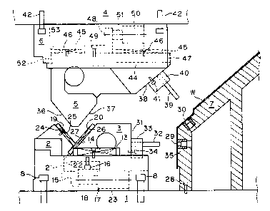
A lower die main body 1 is provided with a slide cam
base 2, a slide cam 3 which is guided by the slide cam base
2 and has a first processing member such as a punch or the
like mounted thereto, a biasing member which is interposed
between the slide cam base 2 and the slide cam 3 so as to
bias the slide cam 3, and a supporting member 7.
An upper die main body 4 is provided with an actuating
cam 5 which is brought into contact with the slide cam base
2 and the slide cam 3 so as to drive the slide cam 3; and
has a second processing member such as a punch or the like
mounted thereto, a guiding member 6 which guides the
actuating cam 5, and a biasing member which is interposed
between the guiding member 6 and the actuating cam 5 so as
to bias the actuating cam 5. Reference symbol W denotes a
work.
4
CA 02480746 2004-09-07
The slide cam base 2 is firmly fixed to the lower die
main body 1 by bolts 8.
Wear plates 10 comprising sliding surfaces, formed in
an inward downward slope and having a trapezoidal cross
section, are firmly fixed to both side bottom portions of a
groove 9 guiding the slide cam 3 of the slide cam base 2.
The slide cam 3 is structured such that a protruding
piece 11 having a rectangular cross section protrudes to a
lower side, sliding surfaces are structured in both sides of
the protruding piece 11, and wear plates 12, formed in an
outward upward slope and having a trapezoidal cross section,
are firmly fixed to both sides: The wear plates 12 slide on
the wear plates 10.
A side end portion of the wear plate 12 protrudes to an
outer side from a side surface of the slide cam 3, a lower
surface of the guide plate 13 is brought into contact with
an upper surface of an outward protruding portion of the
wear plate 12, and the guide plate 13 is firmly fixed to the
slide cam base 2 by bolts 14.
The slide cam 3 slides on the slide cam base 2 in the
manner mentioned above. Further, the wear plate 10 having
the inward downward slope is firmly fixed to the slide cam
base 2, and the wear plate 12 having the outward upward
slope and sliding on the wear plate 10 is firmly fixed to
the slide cam 3. Accordingly, the slide cam 3 is urged to a
center side and accurately slides.
A bracket 15 is firmly fixed to a bottom surface of the
CA 02480746 2004-09-07
slide cam 3 by a bolt 16, and a leading end of a rod 18 of a
gas spring 17 having a base end firmly fixed to the slide
cam base 2 is brought into contact with the bracket 15. As.
long as the actuating cam 5 is moved downward so as to be
brought into contact with a cam slope surface 19 of the
slide cam base 2 and a cam slope surface 20 of the slide cam
3, the rod 18 of the gas spring 17 is contracted. However,
upon upward movement of the actuating cam 5, the rod 18 of
the gas spring 17 is gradually extended, whereby the slide
cam 3 is not brought into contact with the cam slope surface
19 of the slide cam base 2 and the cam slope surface 20 of
the slide cam 3. Then, the rod 18 of the gas spring 17 is
extended so as to bring a rear end surface 21 of the slide
cam 3 into contact with a stop surface 22 of the slide cam
base 2. Accordingly, the slide cam 3 stops.
The gas spring 17 is structured such that a high
pressure gas in correspondence to an intended use, for
example, a high pressL2re gas of 150 kgf/em2 is received
within a cylinder 23, and an approximately uniform output,
for example, 150 kgffcm2 can be obtained all the length of a
rod contraction stroke even when the rod 18 protruding from
the cylinder 23 is expanded and contracted. Two tanks are
installed within the cylinder 23 and when the rod 18 is
contracted and the pressure is applied to one tank, the high
pressure gas flows out from one tank and into the other
tank, whereby an approximately uniform output (the output
may be slightly increased due to compression) can be
6
CA 02480746 2004-09-07
obtained during the whole stroke of the rod 18.
As mentioned above, in the gas spring 17, a high output
can be obtained during the whole stroke from the operation
start, which is different from a coil spring, whereby it is
possible to securely return the slide cam 3 and safe
operation can be achieved.
Furthermore, with the gas spring 17, it is possible to
move the slide cam 3 cver a relatively large distance, and
it is possible to process a thin plate formed product of a
motor vehicle which would be considered to be a large-size
work.
In this case, a wear plate 24 is firmly fixed to the
slide cam base 2 by a bolt 25, a wear plate 26 is firmly
fixed to the slide cam 3 by a bolt 27.
The work W is mounted on the supporting member 7 which
is fixed to the lower die main body 1 by a bolt 28. A first
hole 29 and a second hole 30 are pierced on the work W. An
angle 81 of incline for processing a first processing member
is 0 degree, and an angle 82 of incline for processing a
second processing member is 50 degree. The first hole 29 is
formed on a vertical surface of the work W.
Both the first processing member and the second
processing member are exemplified by piercing in the present
embodiment. However, the present invention is not limited to
piercing, and can include notching, forming and other
processing.
Since the angle ~1 of incline for processing the first
7
CA 02480746 2004-09-07
processing member is 0, this means that a first processing
member mounting surface 31 of the slide cam 3 is a vertical
surface. A punch plate 33 holding a punch 32 is firmly fixed
to the first processing member mounting surface 31 by a bolt
34 in such a manner as to be held in alignment with the
first hole 29.
The first hole 29 forms a hole by the punch 32 and a
die bush 35 buried in the supporting member 7.
The actuating cam 5 has.a slope surface 36 which is
brought into contact with the cam slope surface 19 of the
slide cam base 2, and a slope surface 37 which is brought
into contact with the cam slope surface 20 of the slide cam
3.
The actuating cam 5 has a second working member
mounting surface 38 in addition to the slope surfaces 36 and
3~. The angle 8z of incline for processing the second
processing member is 50 degree, and in order to pierce the
second hole 30 of the work W, a punch 39 is held by a punch
holder 40 so as to be parallel to the second hole 30, and
the punch holder 40 is firmly fixed to the second working
member mounting surface 38 by a bolt 41. An angle of incline
of the cam slope surface of the slide cam base 2 is set to
50 degree which is equal to the angle 62 of incline for
actuating the second processing member, such that the punch
39 moves in a direction having the angle 92.
The guide member 6 for guiding the actuating cam 5 is
firmly fixed to the upper die main body 4 by a bolt 42.
8
CA 02480746 2004-09-07
A groove 43 for guiding the actuating cam 5 of the
guiding member 6 is provided, the upper portion of the
actuating cam 5 is inserted into the groove 43, and a
suspended piece 47 protrudes to an upper side portion of the
actuating cam 5 so as to be slidably engaged with a
supporting piece 44 of the guiding member 6. A wear plate 45
is firmly fixed to an upper surface of the guiding member 6
by a bolt 46.
A bracket 48 is firmly fixed to an upper surface of the
actuating cam 5 by a bolt 49, and a leading end of a rod 51
of a gas spring 50 having a base end firmly fixed to the
guiding member 6 is brought into contact with. the bracket
48. As long as the actuating cam 5 is mo-Ved downward so as
to be brought into contact with a cam slope surface 19 of
the slide cam base 2 and a cam slope surface 20 of the slide
cam 3, the rod 51 of the gas spring 50 is contracted,
however, in accordance with an upward movement of the
actuating cam 5; the rod 51 of the gas spring 50 is
gradually extended, whereby the slide cam 3 is not brought
into contact with the cam slope surface 19 of the slide cam
base 2 and the cam slope surface 20 of the slide cam 3.
Then, the rod 51 of the gas spring 50 is extended so as to
bring a rear end surface 52 of the actuating cam 5 into
contact with a stop surface 53 of_the guiding member 6.
Accordingly, the actuating cam 5 stops.
When piercing the work W, it is necessary to apply a
process to a hole forming surface of the work W from a
9
CA 02480746 2004-09-07
generally vertical direction. In the case that the angle E1
of incline for processing the first processing member is 0
and the angle 8z of Incline for processing the second
working member is 50 degree as in the present embodiment,
the actuating cam, which has been firmly fixed in
conventional dies, is set movable. The actuating cam 5 moves
the slide cam 3 in a direction of actuating the first
processing member, and the actuating cam 5 is moved in the
direction of actuating the second processing member (8z = 50
degree) on the basis of the,angle of incline of the cam
slope surface 19 in the slide cam base 2 (82 = 50 degree).
As a result, the second hole 30 is pierced. In conventional
dies, the second hole cannot be processed in a single step.
The angle 91 of incline for actuating the first
processing member includes 0 degree, 10 degree, 20 degree
and the like, and the angle 82 of incline for actuating the
second processing member includes 40 degree, 50 degree, 60
degree, 70 degree, 80 degree and the like. Various
combinations between the angle 81 of incline for actuating
the first processing member and the angle Az of incline for
actuating the second processing member can be considered.
For example, there are combinations 0 degree - 40 degree, 0
degree - 50 degree, 0 degree - 60 degree, 10 degree - 50
degree, 10 degree - 60 degree, 10 degree - 70 degree, 20
degree - 60 degree, 20 degree - 70 degree, and 20 degree -
80 degree (the former indicates 91, and the latter indicates
l0
CA 02480746 2004-09-07
AZ). A particular combination can be easily selected by
standardizing appropriate replacement parts of the die, and
changes in the combinations can be easily performed.
Setting the angle 81 of incline for actuating the first
processing member to 0 degree, 10 degree or 20 degree means
arranging the first processing member mounting surface 31 so
as to correspond to the angle 81 of incline of O degree, 10
degree or 20 degree. 81 = 0 degree corresponds to an
illustrated state, and 01 = 10 degree corresponds to a state
in which an upper side and a lower side are positioned
respectively to the right and the left with respect to the
state of 81 = 0 degree so as to be inclined at 10 degree.
In order to set the angle 8~ of incline for actuating
the second processing member to 40 degree, 50 degree, 60
degree, 70 degree or 80 degree, it is preferable to form the
second processing member mounting surface 38 so as to
correspond to the angle 82 of incline of 40 degree, 50
degree, 60 degree, 70 degree or 80 degree. 82 = 50 degree
corresponds to an illustrated state, and 62 = 40 degree, 50
degree, 60 degree, 70 degree or 80 degree could require
reshaping a new actuating cam 5 or at least a new punch
holder 40. It is also necessary to change the slide cam base
2 in correspondence to the angle 82 of incline. In order to
easily achieve the change, a hatched replacement member 54
of the slide cam base 2 is structured so as to be
replaceable. The replacement member 54 in which the cam
11
CA 02480746 2004-09-07
slope surface 19 matches to the angle 62 is used.
In a conventional piercing process, three members
comprising the slide cam base, the slide cam and the
actuating cam are required, and in the case where the
piercing process is executed by two steps, three pieces
x 2 = 6 pieces of members are required.
In this case, in accordance with the present invention,
since the piercing process which has been conventionally
executed in two steps is executed in one step, the required
member can be processed by four members comprising the
guiding member in addition to the slide cam base, the slide
cam and the actuating cam. In accordance with the present
invention, the number of the members can. be reduced and a
cost reduction can be achieved.
The present invention can be applied to a notching
process, a bending process, a forming process and other
press dying processes, in addition to ps.ercing, in the
different processing directions.
Since the present invention provides a double acting
cam die comprising a slide cam base, a slide cam which is
guided by the slide cam base and has a first processing
member, such as a punch or the like, mounted thereto, a
biasing member which is interposed between the slide cam
base and the slide cam so as to bias the slide cam, an
actuating cam which is brought into contact with the slide
cam base and the slide cam so as to drive the slide cam, and
has a second processing member, such as a punch or the like,
12
CA 02480746 2004-09-07
mounted thereto, a guiding member which guides the actuating
cam, and a biasing member which is interposed between the
guiding member and the actuating cam so as t,o bias the
actuating cam, it is possible to carry out two die processes
in a single step, even when the processing directions are
different. It is also possible to reduce the number of the
constituent parts of the die required for all the steps of
the press dying, as well as to select a die design, and to
prepare the die and change the die to a new arrangement
easily.
Further, in accordance with a specific aspect of the
present invention, the actuating cam is hung from the
guiding member and is slidably provided thereon.
Further, in accordance with a specific aspect of the
present invention; a wear plate is provided on each sliding
surface between the slide cam and the slide cam base.
Further, in accordance with the specific aspect of the
present invention, a wear plate is interposed on a sliding
surface between the slide cam and the guiding member.
In addition, in accordance with the specific aspect of
the present invention, the biasing member comprises a gas
spring.
13