Sélection de la langue

Search

Sommaire du brevet 2480919 

Énoncé de désistement de responsabilité concernant l'information provenant de tiers

Une partie des informations de ce site Web a été fournie par des sources externes. Le gouvernement du Canada n'assume aucune responsabilité concernant la précision, l'actualité ou la fiabilité des informations fournies par les sources externes. Les utilisateurs qui désirent employer cette information devraient consulter directement la source des informations. Le contenu fourni par les sources externes n'est pas assujetti aux exigences sur les langues officielles, la protection des renseignements personnels et l'accessibilité.

Disponibilité de l'Abrégé et des Revendications

L'apparition de différences dans le texte et l'image des Revendications et de l'Abrégé dépend du moment auquel le document est publié. Les textes des Revendications et de l'Abrégé sont affichés :

  • lorsque la demande peut être examinée par le public;
  • lorsque le brevet est émis (délivrance).
(12) Demande de brevet: (11) CA 2480919
(54) Titre français: PROCEDE ET APPAREIL DE STRATIFICATION
(54) Titre anglais: LAMINATION APPARATUS AND METHODS
Statut: Réputée abandonnée et au-delà du délai pour le rétablissement - en attente de la réponse à l’avis de communication rejetée
Données bibliographiques
(51) Classification internationale des brevets (CIB):
  • B65H 39/14 (2006.01)
  • H01M 04/86 (2006.01)
  • H01M 04/88 (2006.01)
  • H01M 04/92 (2006.01)
  • H01M 04/96 (2006.01)
(72) Inventeurs :
  • RIPLEY, SCOTT A. (Etats-Unis d'Amérique)
  • HIRSCH, DONALD I. (Etats-Unis d'Amérique)
  • BADER, WILLIAM F. (Etats-Unis d'Amérique)
(73) Titulaires :
  • 3M INNOVATIVE PROPERTIES COMPANY
(71) Demandeurs :
  • 3M INNOVATIVE PROPERTIES COMPANY (Etats-Unis d'Amérique)
(74) Agent: SMART & BIGGAR LP
(74) Co-agent:
(45) Délivré:
(86) Date de dépôt PCT: 2003-02-11
(87) Mise à la disponibilité du public: 2003-10-16
Licence disponible: S.O.
Cédé au domaine public: S.O.
(25) Langue des documents déposés: Anglais

Traité de coopération en matière de brevets (PCT): Oui
(86) Numéro de la demande PCT: PCT/US2003/004265
(87) Numéro de publication internationale PCT: US2003004265
(85) Entrée nationale: 2004-09-30

(30) Données de priorité de la demande:
Numéro de la demande Pays / territoire Date
10/115,523 (Etats-Unis d'Amérique) 2002-04-03

Abrégés

Abrégé français

La présente invention concerne des composants pour piles à combustible à membrane électrolytique polymère, ainsi qu'un appareil et des procédés automatisables de fabrication par découpe au tambour emporte-pièce puis par stratification de diverses couches en ensembles électrodes de membrane. L'invention concerne plus particulièrement un appareil et un procédé de production d'un ensemble électrodes de membrane se décomposant en plusieurs opérations. On utilise une membrane électrolytique polymère et un poste de stratification. La bande de membrane électrolytique polymère est tirée entre deux cylindres de stratification du poste de stratification assurant la prise de pince pour la stratification. On découpe à l'emporte-pièce deux bandes de matériau de transfert du catalyseur ou de matériau d'électrode pour réaliser les deux pièces correspondantes sur les deux postes correspondants à tambour emporte-pièce. Ces pièces n'ont généralement pas la forme d'un parallélogramme à quatre côtés. Par un dispositif à dépression, on maintient les pièces découpées sur une bande sans fin perforée de deux convoyeurs à aspiration, généralement avant qu'elles soient complètement détachées des bandes correspondantes. On transporte ces deux pièces vers les faces opposées de la membrane, dans le poste de stratification. Simultanément, on fait avancer les deux pièces dans le pincement des cylindres contre la membrane, généralement avant leur complet dégagement des convoyeurs à aspiration. Il ne reste plus qu'à stratifier sur la membrane les deux pièces ainsi calées en position exacte.


Abrégé anglais


Components for the manufacture of polymer electrolyte membrane fuel cells are
provided, as well as apparatus and automatable methods for their manufacture
by rotary die cutting and by lamination of various layers to form membrane
electrode assemblies. A method and apparatus for performing the method are
provided for making a membrane electrode assembly comprising the steps of
providing a web of polymer electrolyte membrane material (110) and a
laminating station (50), where the web of polymer electrolyte membrane
material (110) is drawn between a pair of laminating rollers (180, 190) in the
laminating station which form a laminating nip; die-cutting a first and second
web of catalyst decal materials or electrode materials to make first and
second workpieces (100) at first and second rotary die stations (10, 20);
which typically have a shape other than a four-sided parallelogram; holding
the die-cut workpieces (100) by action of sub-ambient air pressure to an
endless perforated belt (120) of first and second vacuum conveyors, typically
before they are fully cut from the first and second webs; transporting first
and second workpieces (100) to opposing sides of the membrane (110) in the
laminating station; concurrently feeding the first and second workpieces (100)
into the laminating nip adjacent to the membrane, typically before they are
fully released by the first and second vacuum conveyors (30, 40); and
laminating the first and second workpieces to the membrane, advantageously in
accurate registration.

Revendications

Note : Les revendications sont présentées dans la langue officielle dans laquelle elles ont été soumises.


We claim:
1. A die-cut catalyst decal comprising a liner layer and a co-extensive
catalyst
layer, said catalyst layer comprising particulate catalyst metal, wherein said
decal has a
perimeter which is a shape other than a four-sided parallelogram.
2. A die-cut electrode comprising a fluid transport layer and a co-extensive
catalyst
layer, said catalyst layer comprising particulate catalyst metal, wherein said
electrode
has a perimeter which is a shape other than a four-sided parallelogram.
3. A method of making a die-cut catalyst decal according to claim 1 which
comprises die-cutting a web of catalyst decal material, said web comprising a
liner layer
and a catalyst layer.
4. The method according to claim 3 wherein said step of die-cutting comprises
rotary die-cutting.
5. A method of making a die-cut electrode according to claim 2 which comprises
die-cutting a web of electrode material, said web comprising a fluid transport
layer and
a catalyst layer.
6. The method according to claim 5 wherein said step of die-cutting comprises
rotary die-cutting.
7. A membrane comprising a plurality of membrane electrode assemblies, which
comprises:
a polymer electrolyte membrane having a first and second face;
a plurality of first patterned catalyst layer segments laminated on said first
face
of said membrane such that adjacent patterned catalyst layer segments are not
in contact
with each other; and
-12-

a plurality of second patterned catalyst layer segments laminated on said
second
face of said membrane such that adjacent patterned catalyst layer segments are
not in
contact with each other;
wherein each of said first patterned catalyst layer segments has a perimeter
and
each of said second patterned catalyst layer segments has a perimeter which is
in
accurate registration with a perimeter of an opposing first patterned catalyst
layer
segment.
8. A continuous web containing a plurality of membrane electrode assemblies
which comprises:
a polymer electrolyte membrane having a first and second face;
a plurality of first patterned catalyst layer segments laminated on said first
face
of said membrane such that adjacent patterned catalyst layer segments are not
in contact
with each other; and
a plurality of second patterned catalyst layer segments laminated on said
second
face of said membrane such that adjacent patterned catalyst layer segments are
not in
contact with each other;
wherein each of said first and second patterned catalyst layer segments have a
perimeter which is a shape other than a four-sided parallelogram.
9. The continuous web according to claim 7 wherein each of said first and
second
patterned catalyst layer segments have a perimeter which is a shape other than
a four-
sided parallelogram.
10. The continuous web according to claim 7 wherein said first catalyst layer
segments have a first catalyst composition and said second catalyst layer
segments have
a second catalyst composition that differs from said first catalyst
composition.
11. The continuous web according to claim 8 wherein said first catalyst layer
segments have a first catalyst composition and said second catalyst layer
segments have
a second catalyst composition that differs from said first catalyst
composition.
-13-

12. The continuous web according to claim 9 wherein said first catalyst layer
segments have a first catalyst composition and said second catalyst layer
segments have
a second catalyst composition that differs from said first catalyst
composition.
13. A membrane comprising a plurality of membrane electrode assemblies, which
comprises:
a polymer electrolyte membrane having a first and second face;
a plurality of first patterned electrode layer segments laminated on said
first face
of said membrane such that adjacent patterned electrode layer segments are not
in
contact with each other, each first patterned electrode segment comprising a
fluid
transport layer and a co-extensive layer of a first catalyst; and
a plurality of second patterned electrode layer segments laminated on said
second face of said membrane such that adjacent patterned electrode layer
segments are
not in contact with each other, each second patterned electrode segment
comprising a
fluid transport layer and a co-extensive layer of a second catalyst;
wherein each of said first patterned electrode layer segments has a perimeter
and
each of said second patterned electrode layer segments has a perimeter which
is in
accurate registration with a perimeter of an opposing first patterned
electrode layer
segment.
14. A membrane comprising a plurality of membrane electrode assemblies, which
comprises:
a polymer electrolyte membrane having a first and second face;
a plurality of first patterned electrode layer segments laminated on said
first face
of said membrane such that adjacent patterned electrode layer segments are not
in
contact with each other, each first patterned electrode segment comprising a
fluid
transport layer and a co-extensive layer of a first catalyst; and
a plurality of second patterned electrode layer segments laminated on said
second face of said membrane such that adjacent patterned electrode layer
segments are
-14-

not in contact with each other, each second patterned electrode segment
comprising a
fluid transport layer and a co-extensive layer of a second catalyst;
wherein each of said first and second patterned electrode layer segments have
a
perimeter which is a shape other than a four-sided parallelogram.
15. The continuous web according to claim 13 wherein each of said first and
second
patterned electrode segments have a perimeter which is a shape other than a
four-sided
parallelogram.
16. The continuous web according to claim 13 wherein said first catalyst has a
first
catalyst composition and said second catalyst has a second catalyst
composition that
differs from said first catalyst composition.
17. The continuous web according to claim 14 wherein said first catalyst has a
first
catalyst composition and said second catalyst has a second catalyst
composition that
differs from said first catalyst composition.
18. The continuous web according to claim 15 wherein said first catalyst has a
first
catalyst composition and said second catalyst has a second catalyst
composition that
differs from said first catalyst composition.
19. A method of making a membrane electrode assembly comprising the steps of
a) providing a web of polymer electrolyte membrane material;
b) providing a laminating station wherein said web of polymer electrolyte
membrane material is drawn between a pair of laminating rollers which form a
laminating nip;
c) die-cutting a first web of first catalyst decal material, said web
comprising a
liner layer and a first catalyst layer, to make a first catalyst decal;
d) die-cutting a second web of second catalyst decal material, said web
comprising a liner layer and a second catalyst layer, to make a second
catalyst decal;
e) transporting said first catalyst decal to said laminating station;
-15-

f) transporting said second catalyst decal to said laminating station;
g) feeding said first catalyst decal into said laminating nip adjacent to said
web
of polymer electrolyte membrane material;
h) feeding said second catalyst decal into said laminating nip adjacent to
said
web of polymer electrolyte membrane material concurrently with said first
catalyst
decal;
i) laminating said first catalyst decal, said web of polymer electrolyte
membrane
material and said second catalyst decal to form a laminate.
20. A method of making a continuous web according to claim 7 comprising the
method of claim 19, additionally comprising the step of:
1) repeating steps a)-i).
21. The method according to claim 19 additionally comprising the steps of
m) holding said first catalyst decal by action of sub-ambient air pressure to
an
endless perforated belt of a vacuum conveyor before step c) is complete; and
n) beginning step g) before releasing said first catalyst decal from said
endless
perforated belt of said vacuum conveyor.
22. The method according to claim 21 additionally comprising the steps of
o) holding said second catalyst decal by action of sub-ambient air pressure to
an
endless perforated belt of a vacuum conveyor before step d) is complete; and
p) beginning step h) before releasing said second catalyst decal from said
endless perforated belt of said vacuum conveyor.
23. A method of making a membrane electrode assembly comprising the steps of
a) providing a web of polymer electrolyte membrane material;
b) providing a laminating station wherein said web of polymer electrolyte
membrane material is drawn between a pair of laminating rollers which form a
laminating nip;
-16-

c) die-cutting a first web of first electrode material, said web comprising a
fluid
transport layer and a first catalyst layer, to make a first electrode;
d) die-cutting a second web of second electrode material, said web comprising
a
fluid transport layer and a second catalyst layer, to make a second electrode;
e) transporting said first electrode to said laminating station;
f) transporting said second electrode to said laminating station;
g) feeding said first electrode into said laminating nip adjacent to said web
of
polymer electrolyte membrane material;
h) feeding said second electrode into said laminating nip adjacent to said web
of
polymer electrolyte membrane material concurrently with said first electrode;
i) laminating said first electrode, said web of polymer electrolyte membrane
material and said second electrode to form a laminate.
24. A method of making a continuous web according to claim 13 comprising the
method of claim 23, additionally comprising the step of:
1) repeating steps a)-i).
25. The method according to claim 23 additionally comprising the steps of:
m) holding said first electrode by action of sub-ambient air pressure to an
endless perforated belt of a vacuum conveyor before step c) is complete; and
n) beginning step g) before releasing said first electrode from said endless
perforated belt of said vacuum conveyor.
26. The method according to claim 25 additionally comprising the steps of:
o) holding said second electrode by action of sub-ambient air pressure to an
endless perforated belt of a vacuum conveyor before step d) is complete; and
p) beginning step h) before releasing said second electrode from said endless
perforated
belt of said vacuum conveyor.
27. An apparatus for making a membrane electrode assembly comprising:
a) a lamination station;
-17-

b) a first and second vacuum conveyor; and
c) a first and second rotary die station.
28. The apparatus according to claim 27 wherein said first vacuum conveyor and
said first rotary die station are arranged such that, with said first vacuum
conveyor and
said first rotary die station both functioning, an emerging portion of a
workpiece being
cut from a first web of workpiece material in said first rotary die station
will become
held by said first vacuum conveyor before said workpiece is fully separated
from said
first web of workpiece material.
29. The apparatus according to claim 28 wherein said first vacuum conveyor and
said lamination station are arranged such that, with said first vacuum
conveyor and said
lamination station both functioning, said workpiece is drawn into a laminating
nip of
said lamination station before it is fully released by said first vacuum
conveyor.
30. The apparatus according to claim 29 wherein
said first vacuum conveyor comprises a first endless perforated belt having a
linear surface velocity and a first vacuum conveyor drive mechanism
functionally
connected thereto,
wherein said first rotary die station comprises a first rotary die having a
linear
surface velocity and a first rotary die station drive mechanism functionally
connected
thereto,
wherein said first vacuum conveyor drive mechanism and said first rotary die
station drive mechanism are geared together such that the linear surface
velocity of said
first endless perforated belt is greater than the linear surface velocity of
said first rotary
die.
31. The apparatus according to claim 30 wherein
said lamination station comprises first and second laminating rollers having a
common linear surface velocity and a laminating drive mechanism functionally
connected thereto,
-18-

wherein said first vacuum conveyor drive mechanism and said laminating drive
mechanism are geared together such that the linear surface velocity of said
first endless
perforated belt is equal to the linear surface velocity of said first and
second laminating
rollers.
32. The apparatus according to claim 31 wherein said second vacuum conveyor
and
said second rotary die station are arranged such that, with said second vacuum
conveyor
and said second rotary die station both functioning, an emerging portion of a
workpiece
being cut from a second web of workpiece material in said second rotary die
station will
become held by said second vacuum conveyor before said workpiece is fully
separated
from said second web of workpiece material.
33. The apparatus according to claim 32 wherein said second vacuum conveyor
and
said lamination station are arranged such that, with said second vacuum
conveyor and
said lamination station both functioning, said workpiece is drawn into a
laminating nip
of said lamination station before it is fully released by said second vacuum
conveyor.
34. The apparatus according to claim 33 wherein
said second vacuum conveyor comprises a second endless perforated belt having
a linear surface velocity and a second vacuum conveyor drive mechanism
functionally
connected thereto,
wherein said second rotary die station comprises a second rotary die having a
linear surface velocity and a second rotary die station drive mechanism
functionally
connected thereto,
wherein said second vacuum conveyor drive mechanism and said second rotary
die station drive mechanism are geared together such that the linear surface
velocity of
said second endless perforated belt is greater than the linear surface
velocity of said
second rotary die.
35. The apparatus according to claim 34 wherein said second vacuum conveyor
drive mechanism and said laminating drive mechanism are geared together such
that the
-19-

linear surface velocity of said second endless perforated belt is equal to the
linear
surface velocity of said first and second laminating rollers.
36. An apparatus for making a membrane electrode assembly comprising:
a) a lamination station;
b) a first and second positive grip conveyor; and
c) a first and second rotary die station.
37. The apparatus according to claim 36 wherein said first positive grip
conveyor
and said first rotary die station are arranged such that, with said first
positive grip
conveyor and said first rotary die station both functioning, an emerging
portion of a
workpiece being cut from a first web of workpiece material in said first
rotary die
station will become held by said first positive grip conveyor before said
workpiece is
fully separated from said first web of workpiece material.
38. The apparatus according to claim 37 wherein said first positive grip
conveyor
and said lamination station are arranged such that, with said first positive
grip conveyor
and said lamination station both functioning, said workpiece is drawn into a
laminating
nip of said lamination station before it is fully released by said first
positive grip
conveyor.
-20-

Description

Note : Les descriptions sont présentées dans la langue officielle dans laquelle elles ont été soumises.


CA 02480919 2004-09-30
WO 03/084748 PCT/US03/04265
Lamination Apparatus and Methods
Field of the Invention
This invention relates to components for the manufacture of polymer
electrolyte
membrane fuel cells and apparatus and automatable methods for their
manufacture by
lamination of various layers to form membrane electrode assemblies.
Background of the Invention
U.S. Pats. Nos. 6,159,327, 6,007,660 and 5,73,024 disclose an apparatus and
method for making a plurality of substrates laminated on one or two sides with
scissor-
cut sheets of laminate.
Summary of the Invention
Briefly, the present invention provides a method for making a membrane
electrode assembly comprising the steps of providing a web of polymer
electrolyte
membrane material and a laminating station, where the web of polymer
electrolyte
membrane material is drawn between a pair of laminating rollers in the
laminating
station which form a laminating nip; die-cutting a first and second web of
catalyst decal
materials or electrode materials to make first and second workpieces at first
and second
rotary die stations; holding the die-cut workpieces by action of sub-ambient
air pressure
to an endless perforated belt of first and second vacuum conveyors, typically
before
they are fully cut from the first and second webs; transporting first and
second
workpieces to opposing sides of the membrane in the laminating station;
concurrently
feeding the first and second workpieces into the laminating nip adjacent to
the
membrane, typically before they are fully released by the first and second
vacuum
conveyors; and laminating the first and second workpieces to the membrane,
advantageously in accurate registration.
-1-

CA 02480919 2004-09-30
WO 03/084748 PCT/US03/04265
In another aspect, the present invention provides an apparatus for making a
membrane electrode assembly comprising a lamination station; a first and
second
vacuum conveyor; and a first and second rotary die station. These five
components
may be situated and geared together so that first and second workpieces
emerging from
first and second rotary die stations are held by action of sub-ambient air
pressure to the
endless perforated belt of first and second vacuum conveyors before they are
fully cut
from the first and second webs and are fed into the laminating nip adjacent to
the
membrane before they are released by the vacuum conveyors.
In another aspect, the present invention provides a membrane comprising a
plurality of membrane electrode assemblies, which comprises a polymer
electrolyte
membrane having a first and second face; a plurality of first patterned
catalyst layer
segments or electrodes laminated on the first face of the membrane such that
adjacent
patterned catalyst layer segments are not in contact with each other; and a
plurality of
second patterned catalyst layer segments or electrodes laminated on the second
face of
the membrane such that adjacent patterned catalyst layer segments are not in
contact
with each other. Typically the first patterned catalyst layer segments or
electrodes are
in accurate registration with the second patterned catalyst layer segments or
electrodes.
Typically each of said first and second patterned catalyst layer segments or
electrodes
have a perimeter which is a shape other than a four-sided parallelogram. The
first
catalyst layer segments or electrodes may have a catalyst composition that
differs from
the catalyst composition of the second catalyst layer segments or electrodes.
In another aspect, the present invention provides a die-cut catalyst decal or
electrode which has a perimeter which is a shape other than a four-sided
parallelogram,
typically made by a method of rotary die cutting.
In this application:
"to laminate" means to bond together two or more sheet materials; and
"membrane electrode assembly" means a construction comprising at least three
layers, including a catalyst layer, a layer of a polymer electrolyte membrane,
and
another catalyst layer, and which may also comprise five layers, including a
fluid
transport layer, a catalyst layer, a layer of a polymer electrolyte membrane,
another
catalyst layer, and another fluid transport layer; and
_2_

CA 02480919 2004-09-30
WO 03/084748 PCT/US03/04265
"fluid transport layers" may include layers previously termed
"diffuser/current
collector" (DCC) layers, "gas diffusion layers" (GDL), or "electrode backing
layers"
(EBL's).
It is an advantage of the present invention to provide methods, apparatus, and
components for the manufacture of polymer electrolyte membrane fuel cells.
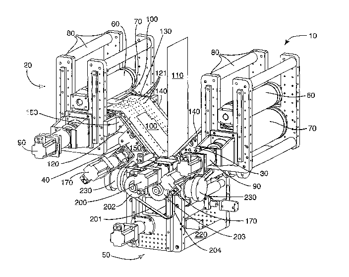
Brief Description of the Drawing
Figs. 1 and 2 illustrate two views of an apparatus according to the present
invention.
Detailed Description of Preferred Embodiments
With reference to Figs. 1 and 2, an apparatus according to the present
invention
comprises a pair of rotary die stations 10, 20, a pair of angled vacuum
conveyors 30, 40,
and a lamination station 50. Angled vacuum conveyors 30, 40 may be the vacuum
conveyors described in co-pending U.S. Patent Application / , , titled "Angled
Product Transfer Conveyor," filed on even date herewith. Each combination of
die
station and angled vacuum conveyor, 10 with 30 and 20 with 40, may comprise
the
apparatus for cutting and transporting sheet materials described in co-pending
U.S.
Patent Application / , '-, titled "Angled Product Transfer Conveyor," filed on
even date herewith. Lamination station 50 may comprise the gapping block and
other
lamination apparatus described in co-pending U.S. Patent Application / , ,
titled "Gap Adjuster for Laminating Rolls," filed on even date herewith.
Any suitable rotary die station may be used. Each rotary die station 10, 20
comprises a rotary die 60, anvil roll 70 rotatably attached to a frame
comprising frame
elements 80. One or both of rotary die 60 and anvil roll 70 are driven. Rotary
die 60
and anvil roll 70 are typically geared together by electronic or mechanical
gearing. In
the apparatus as depicted, anvil roll 70 is driven by servo motor.90 and
mechanically
geared to rotary die 60. Any suitable combination of rotary die 60 and anvil
roll 70 may
be employed. Rotary die 60 typically comprises a cutting edge or edges (not
apparent
in Figs. 1 and 2) wrapped around the outer portion of a roller having a
suitable depth for
the material to be cut. Unlike simple chopping or scissoring apparatus, which
can
-3-

CA 02480919 2004-09-30
WO 03/084748 PCT/US03/04265
produce workpieces having a shape selected from the set of four-sided
parallelograms,
rotary die 60 can produce cut workpieces 100 of arbitrary shape, including
curved
portions such as rounded corners, from a continuous web (not shown). Typical
die-cut
shapes have rounded corners, due to the limitations of die machining, and are
therefore
not four-sided parallelograms. The continuous web and cut workpieces 100 may
be of
any suitable material to be laminated to membrane 110.
fil one embodiment according to the present invention, useful in the
manufacture of membrane electrode assemblies for fuel cells, workpieces 100
axe
catalyst decals comprising a liner layer and a co-extensive catalyst layer
which
comprises particulate catalyst metal. Such workpieces are cut from a
continuous web
of the liner layer coated with the catalyst layer on at least a portion
passing under the
cutting portion of rotary die 60. Any suitable liner may be used, including
any suitably
flexible polymeric sheet materials having a thickness of typically less than 1
millimeter,
more typically less than .5 millimeter, and more typically less than .2
millimeter. The
catalyst layer may be applied by any suitable method, including bax coating,
spray
coating, slit coating, brush coating, and the like. The catalyst layer
typically has a
thickness of less than 1 millimeter, more typically less than .5 millimeter,
and more
typically less than .2 millimeter. Any suitable catalyst composition may be
used.
Typical catalyst compositions fine particles of platinum, palladium, ruthenium
and
other catalyst metals, or combinations of catalyst metals, supported on carbon
particles.
The caxbon-supported catalyst particles are typically 50-60% carbon and 40-50%
catalyst metal by weight, the catalyst metal typically comprising Pt for the
cathode and
Pt and Ru in a weight ratio of 2:1 for the anode. Typical catalyst
compositions may
also include polymer electrolyte materials such as sulfonated fluoropolymers,
including
NafionTM or FlemionTM. After the catalyst decal is laminated the liner is
typically
removed.
In another embodiment according to the present invention, also useful in the
manufacture of membrane electrode assemblies for fuel cells, workpieces 100
are
electrodes comprising a fluid transport layer and a co-extensive catalyst
layer which
comprises particulate catalyst metal. Such workpieces are cut from a
continuous web
of the fluid transport layer coated with the catalyst layer on at least a
portion passing
-4-

CA 02480919 2004-09-30
WO 03/084748 PCT/US03/04265
under the cutting portion of rotary die 60. Any suitable fluid transport layer
may be
used. Suitable fluid transport layers for fuel cell use are porous, to allow
passage of
fluids, and electrically conductive. Typical fluid transport layers include
carbon fiber
fabrics, mats, non-wovens and papers, such as Toray Carbon Paper (Toray
Industries,
Inc., Tokyo, Japan). The catalyst layer may be applied by any suitable method,
including bar coating, spray coating, slit coating, brush coating, and the
like. Any
suitable catalyst composition may be used. Typical catalyst compositions fine
particles
of platinum, palladium, ruthenium and other catalyst metals, or combinations
of catalyst
metals, supported on carbon particles. The carbon-supported catalyst particles
are
typically 50-60% carbon and 40-50% catalyst metal by weight, the catalyst
metal
typically comprising Pt for the cathode and Pt and Ru in a weight ratio of 2:1
for the
anode. Typical catalyst compositions may also include polymer electrolyte
materials
such as sulfonated fluoropolymers, including NafionTM or FlemionTM. Prior to
coating
with the catalyst dispersion, the gas diffusion layer has typically been
coated with a
hydrophobic layer such as TeflonTM, typically by dipping in an aqueous
suspension
thereof, and then has typically been coated with a carbon black dispersion.
The carbon
black dispersion is typically an aqueous dispersion comprising carbon black
and Teflon
and optionally a surfactant such as TRITON X-100 (Union Carbide Corp.,
Danbury,
CT). More typically, the dispersant is a combination of water and isopropyl
alcohol,
typically comprising more than 60% by weight isopropyl alcohol. The carbon
black
dispersion is typically coated onto the dried Toray paper at a wet thickness
of 0.01 to
0.1 mm. The Teflon and carbon black coated fluid transport layer is typically
dried in
an oven at 380°C for 10 minutes. This coated fluid transport layer is
then further
coated with the catalyst, typically in an amount yielding 0.2-5 mg of catalyst
metal (Pt
or Pt plus Ru) per square centimeter, typically about 0.5 mg of catalyst metal
(Pt or Pt
plus Ru) per square centimeter, to form a catalyst-coated fluid transport
layer.
In embodiments according to the present invention useful in the manufacture of
membrane electrode assemblies for fuel cells, membrane 110 is a polymer
electrolyte
membrane, such as a sulfonated fluoropolymer membrane, such as Nafion~ (DuPont
Chemicals, Wilinington DE) and FlemionT"" (Asahi Glass Co. Ltd., Tokyo,
Japan). The
polymer electrolytes useful in the present invention are typically copolymers
of
-5-

CA 02480919 2004-09-30
WO 03/084748 PCT/US03/04265
tetrafluoroethylene and one or more fluorinated, acid-functional comonomers,
typically
bearing sulfonate functional groups. Most typically the polymer electrolyte is
Nafion~.
The polymer electrolyte typically has an acid equivalent weight of 1200 or
less, more
typically 1100 or less, more typically 1050 or less, and most typically about
1000. The
polymer electrolyte membrane may be cast, coated or otherwise formed from a
suspension. Any suitable method of coating or casting may be used, including
bar
coating, spray coating, slit coating, brush coating, and the like. Membrane
110 is
typically 100 micrometers in thickness or less, more typically 50 micrometers
in
thickness or less, and more typically 30 micrometers in thickness or less.
Any suitable vacuum conveyors may be used. Angled vacuum conveyors 30, 40
comprise endless perforated belts 120 perforated with belt holes 121. The belt
may be
made of any suitable material, including polymers, rubbers, fabrics,
composites, and the
like, provided that the outer surface is compatible with workpiece 110 to be
transported
on the belt. Endless perforated belt 120 passes over first vacuum plate 130
having
longitudinal openings, not shown, and second vacuum plate 140 having
longitudinal
openings, not shown. Belt holes 121 are arranged in rows aligned with the
longitudinal
openings. Typically, each vacuum plate 130, 140 has at least two longitudinal
openings
aligned with at least two rows of belt holes 121. More typically, each vacuum
plate
130, 140 has four or more longitudinal openings aligned with four or more rows
of belt
holes 121, so as to enable the vacuum conveyor to grip workpieces 100 of
varying sizes
across the majority of their width. In the embodiment as depicted, endless
perforated
belts 120 are driven in a direction toward the vacuum plate which angles
downward for
delivery of the workpiece 100 to laminating station 50.
Longitudinal openings in first and second vacuum plates 130, 140 communicate
with first and second vacuum chambers (not shown), respectively. First and
second
vacuum chambers are maintained at first and second sub-ambient air pressures,
such
that the sub-ambient air pressures tend to hold workpiece 100 to endless
perforated belt
120. First and second sub-ambient air pressures may be the same or different.
Where
first and second sub-ambient air pressures are different, the first sub-
ambient air
pressure is typically less than the second, enabling the conveyor to better
hold
workpieces 100 coming onto the conveyor at locations over first vacuum plate
130 and
-6-

CA 02480919 2004-09-30
WO 03/084748 PCT/US03/04265
release workpieces leaving the conveyor from locations over second vacuum
plate 140.
The first and second vacuum chambers are maintained at first and second sub-
ambient
air pressures by any suitable means. The vacuum chambers may be functionally
connected to one or more sources of sub-ambient air pressure such as vacuum
pumps
and the like.
First vacuum plate 130 is situated at a first angle relative to horizontal,
which is
approximately 0°. Second vacuum plate 140 is situated at second angle
relative to
horizontal, which is approximately -45°. Typically, the first and
second angles are not
equal. Typically, the first angle is between 30° and -30°
relative to horizontal and said
second angle is between -30° and -90° relative to horizontal.
More typically, the first
angle is between 5° and -5° relative to horizontal and said
second angle is between -40°
and -50° relative to horizontal. These angles allow angled vacuum
conveyors 30, 40, to
receive workpieces 100 from rotary die stations 10, 20, and deliver workpieces
100
downward into the laminating nip of lamination station 50.
First and second vacuum plates 130, 140 are mounted to a frame made up of one
or more frame elements 150. Endless perforated belt 120 passes over a number
of
rollers rotatably mounted to frame elements 150. Endless perforated belt 120
also
passes through drive mechanism 160 powered by servo motor 170.
In the place of vacuum conveyors, any positive grip conveyor may alternately
be
used. Positive grip conveyors may include known pick-and-place mechanisms,
including those comprising armature mechanisms, known two-belt conveyors,
which
employ a pair of belts to form an extended nip to convey a workpiece, and
known static
electricity conveyors which hold a workpiece to a endless belt by the use of a
static
electric charge. Vacuum conveyors are advantageously used for handling
delicate
workpieces.
Lamination station 50 comprises first laminating roller 180 and second
laminating roller 190. Either or both of first laminating roller 180 and
second
laminating roller 190 may be driven by known means such as motors and the
like.
Typically both are driven. Typically first laminating roller 180 and second
laminating
roller 190 are geared together so that they have the same speed at~the gap. In
one
embodiment, first laminating roller 180 and second laminating roller 190 are
driven by
_7_

CA 02480919 2004-09-30
WO 03/084748 PCT/US03/04265
servo motor 200 which drives belt 201 and pulleys 202, 203. A belt tensioning
system,
not shown, maintains bend 204.
Typically first laminating roller 180 and second laminating roller 190 ride in
bearings 210, which are of known types such as ball bearings, roller bearings,
needle
bearings, and the like. Bearings 210 are attached to the apparatus frame 220
such that
pressure can be brought or maintained on bearings 210 which tends to bring
together
first and second laminating rollers 180, 190. The bearing housings may be
fixedly
attached to frame 220 or attached by means of pneumatic or hydraulic pistons
and
cylinders 230, as shown. Bearing mechanisms may form a part of drive
mechanisms
for either or both rollers.
First laminating roller 180 and second laminating roller 190 may be heated by
any suitable method but are typically internally heated by a method such as
electrical
heating or circulation of hot air, water or oil.
Typically, a minimum laminating gap is maintained between first laminating
roller 180 and second laminating roller 190. This minimum laminating gap is
typically
maintained by use of the gapping block described in co-pending TJ.S. Patent
Application / , , titled "Gap Adjuster for Laminating Rolls," filed on even
date
herewith. By maintaining a minimum gap in this manner, the apparatus according
to
the present invention may be used for intermittent lamination, i.e., where one
or more
of the layers to be laminated is not continuously present in the laminating
gap during
lamination. In that case, the product may be a continuous web with non-
continuous
patches of additional sheet materials laminated thereto. In the case of
intermittent
lamination, the continuous web could be crushed or damaged if the full
laminating
pressure were applied when the non-continuous sheet material was not present
in the
gap.
Typically, webs of laminating cover liner are introduced on either side of the
laminating nip during lamination, so that first laminating roller 180 and
second
laminating roller 190 are covered by a first laminating cover liner and a
second
laminating cover liner, respectively, during lamination. The use of laminating
cover
liners may enable higher temperature lamination. After lamination, first and
second
laminating cover liners are removed from the laminate and rewound. Any
suitable
_g_

CA 02480919 2004-09-30
WO 03/084748 PCT/US03/04265
material may be used for first and second laminating cover liners, so long as
the
material will not become laminated under the laminating conditions and will
not impart
any undesirable texture to the laminate.
Angled vacuum conveyors 30, 40 and rotary die stations 10, 20 are
advantageously arranged such that an emerging portion of a workpiece 100 being
cut
from a web of workpiece material can become held by the action of the first
sub-
ambient pressure in the first vacuum chamber, drawing air through first vacuum
plate
130 and endless perforated belt 120, before workpiece 100 is fully separated
from the
web of workpiece material. Angled vacuum conveyors 30, 40 and laminating
station 50
are advantageously arranged such that a leading edge of a workpiece 100 being
transported by an angled vacuum conveyor 30, 40 is drawn into the laminating
nip of
lamination station 50 before it is fully released by the angled vacuum
conveyor 30, 40.
Most advantageously, both arrangements are made, so that workpiece 100 is held
by
angled vacuum conveyors 30, 40 before workpiece 100 is fully separated from
the web
of workpiece material and workpiece 100 is drawn into the laminating nip of
lamination
station 50 before it is fully released by the angled vacuum conveyor 30, 40.
In this way,
positive control of workpiece location is maintained through every step. As a
result,
membrane 110 may be laminated on both sides with accurate registration.
Accurate
registration typically means that the perimeters of the pattern-cut sheet
materials match
to within 2 mm, more typically 1 mm, more typically 0.5 mm, more typically 250
~.m,
and more typically 125 ~.m.
Drive mechanisms for rotary die stations 10, 20, angled vacuum conveyors 30,
40, and lamination station 50 are advantageously geared or synchronized
together, by
mechanical or more typically by electronic gearing. The drive mechanism for
propelling endless perforated belt 120 may be geared with the drive mechanism
driving
rotary die 60 such that the linear surface velocity of endless perforated belt
120 may be
equal to or greater than the lineax surface velocity of rotary die 60. A
greater velocity
enables the conveyor to space apart workpieces 100 as they emerge from rotary
die 60,
so that workpieces 100 may be cut with no intervening scrap but placed with
intervening margins. The drive mechanism for propelling endless perforated
belt 120
may be geared with the drive mechanism driving first and second laminating
rollers
-9-

CA 02480919 2004-09-30
WO 03/084748 PCT/US03/04265
180, 190 such that the linear surface velocity of first and second laminating
rollers 180,
190 may be equal to or greater than the linear surface velocity of endless
perforated belt
120.
In the method according to the present invention, a membrane 110 such as a
web of polymer electrolyte membrane material is drawn between laminating
rollers
180, 190 in laminating station 50 which form a laminating nip. A first and
second web
of laminate material is die-cut at rotary die stations 10, 20 to form cut
workpieces 100.
The first and second webs of laminate material may be the same or different.
The first
and second webs of laminate material may be catalyst decal materials
comprising a liner
layer and a first catalyst layer, or electrode material comprising a fluid
transport layer
and a first catalyst layer. The cut workpieces 100 are transported to
laminating station
50 by vacuum conveyors 30 and 40 and concurrently fed into the laminating nip
between laminating rollers 180 and 190 on either side of membrane 110 to form
a
laminate. Advantageously, workpieces 100 come to be held by action of sub-
ambient
air pressure to vacuum conveyors 30 and 40 before they are completely
separated from
first or second webs of laminate material. Advantageously workpieces 100 are
gripped
by the laminating nip between laminating rollers 180 and 190 before they are
released
from vacuum conveyors 30 and 40.
The lamination may be repeated to form a continuous web of membrane linking
similar laminates.
Where membrane 110 is a polymer electrolyte membrane, as described above,
and workpieces 100 are catalyst decals, as described above, the method and
apparatus
according to the present invention may be used to produce a continuous
membrane that
comprises a plurality of membrane electrode assemblies, all comprising first
and second
patterned catalyst layer segments which axe in accurate registration. The
first and
second patterned catalyst layer segments can have a perimeter which is a shape
other
than a four-sided parallelogram. Typical die-cut shapes have rounded corners,
and may
additionally form any of a large number of arbitrary perimeter shapes. The
first and
second patterned catalyst layer segments can have the same or different
catalyst
composition.
-10-

CA 02480919 2004-09-30
WO 03/084748 PCT/US03/04265
Where membrane 110 is a polymer electrolyte membrane, as described above,
and workpieces 100 are electrodes comprising a fluid transport layer and a co-
extensive
catalyst layer catalyst decals, as described above, the method and apparatus
according to
the present invention may be used to produce a continuous membrane that
comprises a
plurality of membrane electrode assemblies, all comprising first and second
patterned
electrode segments which are in accurate registration. The first and second
patterned
electrode segments can have a perimeter which is a shape other than a four-
sided
parallelogram. Typical die-cut shapes have rounded corners, and may
additionally form
any of a large number of arbitrary perimeter shapes. The first and second
patterned
electrode segments can have the same or different catalyst composition.
Various modifications and alterations of this invention will become apparent
to
those skilled in the art without departing from the scope and principles of
this
invention, and it should be understood that this invention is not to be unduly
limited to
the illustrative embodiments set forth hereinabove.
-11-

Dessin représentatif
Une figure unique qui représente un dessin illustrant l'invention.
États administratifs

2024-08-01 : Dans le cadre de la transition vers les Brevets de nouvelle génération (BNG), la base de données sur les brevets canadiens (BDBC) contient désormais un Historique d'événement plus détaillé, qui reproduit le Journal des événements de notre nouvelle solution interne.

Veuillez noter que les événements débutant par « Inactive : » se réfèrent à des événements qui ne sont plus utilisés dans notre nouvelle solution interne.

Pour une meilleure compréhension de l'état de la demande ou brevet qui figure sur cette page, la rubrique Mise en garde , et les descriptions de Brevet , Historique d'événement , Taxes périodiques et Historique des paiements devraient être consultées.

Historique d'événement

Description Date
Inactive : CIB expirée 2016-01-01
Demande non rétablie avant l'échéance 2009-02-11
Le délai pour l'annulation est expiré 2009-02-11
Réputée abandonnée - omission de répondre à un avis sur les taxes pour le maintien en état 2008-02-11
Inactive : Abandon.-RE+surtaxe impayées-Corr envoyée 2008-02-11
Inactive : CIB de MCD 2006-03-12
Inactive : Page couverture publiée 2004-12-13
Lettre envoyée 2004-12-09
Inactive : Notice - Entrée phase nat. - Pas de RE 2004-12-09
Inactive : IPRP reçu 2004-12-01
Demande reçue - PCT 2004-11-01
Exigences pour l'entrée dans la phase nationale - jugée conforme 2004-09-30
Demande publiée (accessible au public) 2003-10-16

Historique d'abandonnement

Date d'abandonnement Raison Date de rétablissement
2008-02-11

Taxes périodiques

Le dernier paiement a été reçu le 2007-01-18

Avis : Si le paiement en totalité n'a pas été reçu au plus tard à la date indiquée, une taxe supplémentaire peut être imposée, soit une des taxes suivantes :

  • taxe de rétablissement ;
  • taxe pour paiement en souffrance ; ou
  • taxe additionnelle pour le renversement d'une péremption réputée.

Les taxes sur les brevets sont ajustées au 1er janvier de chaque année. Les montants ci-dessus sont les montants actuels s'ils sont reçus au plus tard le 31 décembre de l'année en cours.
Veuillez vous référer à la page web des taxes sur les brevets de l'OPIC pour voir tous les montants actuels des taxes.

Historique des taxes

Type de taxes Anniversaire Échéance Date payée
Taxe nationale de base - générale 2004-09-30
TM (demande, 2e anniv.) - générale 02 2005-02-11 2004-09-30
Enregistrement d'un document 2004-09-30
TM (demande, 3e anniv.) - générale 03 2006-02-13 2006-01-18
TM (demande, 4e anniv.) - générale 04 2007-02-12 2007-01-18
Titulaires au dossier

Les titulaires actuels et antérieures au dossier sont affichés en ordre alphabétique.

Titulaires actuels au dossier
3M INNOVATIVE PROPERTIES COMPANY
Titulaires antérieures au dossier
DONALD I. HIRSCH
SCOTT A. RIPLEY
WILLIAM F. BADER
Les propriétaires antérieurs qui ne figurent pas dans la liste des « Propriétaires au dossier » apparaîtront dans d'autres documents au dossier.
Documents

Pour visionner les fichiers sélectionnés, entrer le code reCAPTCHA :


Pour visualiser une image, cliquer sur un lien dans la colonne description du document (Temporairement non-disponible). Pour télécharger l'image (les images), cliquer l'une ou plusieurs cases à cocher dans la première colonne et ensuite cliquer sur le bouton "Télécharger sélection en format PDF (archive Zip)" ou le bouton "Télécharger sélection (en un fichier PDF fusionné)".

Liste des documents de brevet publiés et non publiés sur la BDBC .

Si vous avez des difficultés à accéder au contenu, veuillez communiquer avec le Centre de services à la clientèle au 1-866-997-1936, ou envoyer un courriel au Centre de service à la clientèle de l'OPIC.

({010=Tous les documents, 020=Au moment du dépôt, 030=Au moment de la mise à la disponibilité du public, 040=À la délivrance, 050=Examen, 060=Correspondance reçue, 070=Divers, 080=Correspondance envoyée, 090=Paiement})


Description du
Document 
Date
(aaaa-mm-jj) 
Nombre de pages   Taille de l'image (Ko) 
Description 2004-09-29 11 628
Revendications 2004-09-29 9 398
Abrégé 2004-09-29 2 105
Dessins 2004-09-29 2 97
Dessin représentatif 2004-09-29 1 51
Avis d'entree dans la phase nationale 2004-12-08 1 193
Courtoisie - Certificat d'enregistrement (document(s) connexe(s)) 2004-12-08 1 106
Rappel - requête d'examen 2007-10-14 1 127
Courtoisie - Lettre d'abandon (taxe de maintien en état) 2008-04-06 1 175
Courtoisie - Lettre d'abandon (requête d'examen) 2008-05-04 1 167
PCT 2004-09-29 5 154
PCT 2004-09-29 4 155