Sélection de la langue

Search

Sommaire du brevet 2481351 

Énoncé de désistement de responsabilité concernant l'information provenant de tiers

Une partie des informations de ce site Web a été fournie par des sources externes. Le gouvernement du Canada n'assume aucune responsabilité concernant la précision, l'actualité ou la fiabilité des informations fournies par les sources externes. Les utilisateurs qui désirent employer cette information devraient consulter directement la source des informations. Le contenu fourni par les sources externes n'est pas assujetti aux exigences sur les langues officielles, la protection des renseignements personnels et l'accessibilité.

Disponibilité de l'Abrégé et des Revendications

L'apparition de différences dans le texte et l'image des Revendications et de l'Abrégé dépend du moment auquel le document est publié. Les textes des Revendications et de l'Abrégé sont affichés :

  • lorsque la demande peut être examinée par le public;
  • lorsque le brevet est émis (délivrance).
(12) Demande de brevet: (11) CA 2481351
(54) Titre français: GROUPE DE SUPPORTS DE TAILLE VARIABLE DISPOSES DANS LE SENS DE L'ENVERGURE
(54) Titre anglais: SPANWISELY VARIABLE DENSITY PEDESTAL ARRAY
Statut: Réputée abandonnée et au-delà du délai pour le rétablissement - en attente de la réponse à l’avis de communication rejetée
Données bibliographiques
(51) Classification internationale des brevets (CIB):
  • F01D 25/12 (2006.01)
  • F01D 05/18 (2006.01)
(72) Inventeurs :
  • MONGILLO, DOMINIC J., JR. (Etats-Unis d'Amérique)
  • CHON, YOUNG H. (Etats-Unis d'Amérique)
(73) Titulaires :
  • UNITED TECHNOLOGIES CORPORATION
(71) Demandeurs :
  • UNITED TECHNOLOGIES CORPORATION (Etats-Unis d'Amérique)
(74) Agent: NORTON ROSE FULBRIGHT CANADA LLP/S.E.N.C.R.L., S.R.L.
(74) Co-agent:
(45) Délivré:
(22) Date de dépôt: 2004-09-13
(41) Mise à la disponibilité du public: 2005-05-19
Requête d'examen: 2004-09-13
Licence disponible: S.O.
Cédé au domaine public: S.O.
(25) Langue des documents déposés: Anglais

Traité de coopération en matière de brevets (PCT): Non

(30) Données de priorité de la demande:
Numéro de la demande Pays / territoire Date
10/717,806 (Etats-Unis d'Amérique) 2003-11-19

Abrégés

Abrégé anglais


A turbine engine component, such as a blade or vane, has a system for cooling
a
trailing edge portion thereof. The system includes a plurality of rows of
pedestals which vary
in density along a span of the component. In a preferred embodiment of the
present invention,
the number of rows of pedestals increases as one moves along the span of the
component
from an inner diameter region to an outer diameter region.

Revendications

Note : Les revendications sont présentées dans la langue officielle dans laquelle elles ont été soumises.


CLAIMS
1. A turbine engine component having a trailing edge portion, said component
comprising:
means for cooling the trailing edge portion; and
said cooling means comprising a plurality of rows of pedestals which varies
into
density along a span of the component.
2. A turbine engine component according to claim 1, wherein the number of rows
of
pedestals increases as one moves along the span of the component from an inner
diameter
region to an outer diameter region.
3. A turbine engine component according to claim 1, wherein the number of rows
of
pedestals in an outer diameter region of said component is greater than the
number of rows of
pedestals in an inner diameter region of said component.
4. A turbine engine component according to claim 3, wherein the number of
pedestal rows in
the outer diameter region is at least twice as many as the number of pedestal
rows in the inner
diameter region.
5. A turbine engine component according to claim 3, wherein there are seven
pedestal rows in
the outer diameter region and three pedestal rows in the inner diameter
region.
6. A turbine engine component according to claim 1, wherein said cooling means
further
comprises a cooling passage having an inlet at the outer diameter of the
component, which
cooling passage provides a cooling fluid to said pedestal rows, and a
plurality of slots along a
trailing edge of said component through which said cooling fluid is exhausted,
which slots
are in fluid communication with a region containing said pedestal rows.
7. A turbine engine component according to claim 6, wherein said variable
density pedestal
rows optimizes trailing edge slot coolant Mach number and velocity with
coolant air
temperature rise and local thermal convective efficiency and performance.
5

8. A turbine engine component according to claim 1, wherein said component
comprises a
vane and said cooling means is located in an airfoil portion of said vane.
9. A turbine engine component according to claim 1, wherein said component
comprises a
blade and said cooling means is located in an airfoil portion of said blade.
10. A turbine engine component comprising:
an airfoil portion having an outer edge portion and an inner edge portion;
a cooling passageway located in said airfoil portion for providing cooling
fluid to a
trailing edge portion of said airfoil portion;
a plurality of cooling slots in said trailing edge portion for exhausting said
cooling
fluid; and
means for uniformly optimizing trailing edge slot coolant Mach number and
velocity
with coolant air temperature rise and local thermal convective efficiency and
performance.
11. A turbine engine component according to claim 10, wherein said uniformly
optimizing
means comprises a plurality of rows of pedestals having a spanwise variable
density.
12. A turbine engine component according to claim 11, wherein the number of
rows of said
pedestals adjacent said inner edge is less than the number of rows of said
pedestals adjacent
said outer edge.
6

Description

Note : Les descriptions sont présentées dans la langue officielle dans laquelle elles ont été soumises.

EH-10997(03-531 )
CA 02481351 2004-09-13
SPANWISELY VARIABLE DENSITY PEDESTAL ARRAY
STATEMENT OF GOVERNMENT INTEREST
The Government of the United States of America may have rights in the present
invention as a result of Contract No. N00019-02-C-3003 awarded by the
Department of the
Navy.
BACKGROUND OF THE INVENTION
(I) Field of the Invention
The present invention relates to a component for use in a turbine engine, such
as a
vane or blade, having improved trailing edge cooling.
(2) Prior Art
Turbine engine components such as vanes and blades are subject to temperature
extremes. Thus, it becomes necessary to cool various portions of the
components. Typically,
the trailing edge portions of such components are provided with cooling
passages and a series
of outlets along the trailing edge communication with the passages. Despite
the existence of
such structures, there remains a need for improved trailing edge cooling of
such components.
SUMMARY OF THE INVENTION
Accordingly, it is an object of the present invention to provide a turbine
engine
component having a spanwisely variable density pedestal array for improving
spanwise
uniformity of the exhaustive coolant.
It is a further object of the present invention to provide a turbine engine
component
having a spanwisely variable density pedestal array which optimizes internal
cooling fluid
heat up.
The foregoing objects are attained by the turbine engine component of the
present
invention.
In accordance with the present invention, a turbine engine component has means
for
cooling a trailing edge portion, which means comprises a plurality of rows of
pedestals which
vary in density along a span of the component. In a preferred embodiment of
the present
invention, the number of rows of pedestals increases as one moves along the
span of the
component from an inner diameter region to an outer diameter region.

EH-10997(03-531 )
CA 02481351 2004-09-13
Other details of the spanwisely variable density pedestal arrays of the
present
invention, as well as other objects and advantages attendant thereto, are set
forth in the
following detailed description and the accompanying drawings wherein like
reference
numerals depict like elements.
BRIEF DESCRIPTION OF THE DRAWINGS
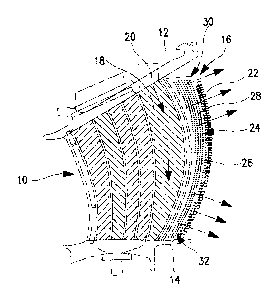
FIG. 1 is a schematic representation of a turbine vane having a spanwisely
variable
density pedestal array in accordance with the present invention;
FIG. 2 is an enlarged view of the pedestal array at an outer diameter portion
of the
vane of FIG. 1;
FIG. 3 is an enlarged view of the pedestal array at an inner diameter portion
of the
vane of FIG. 1;
FIG. 4 is a graph illustrating the trailing edge heat-up through multiple rows
of
pedestals in accordance with the present invention;
FIG. 5 is a graph illustrating the pressure drop across the trailing edge of
the vane
using the pedestal array of the present invention; and
FIG. 6 is a graph showing the flow distribution through the trailing edge of a
vane
using the pedestal array of the present invention.
DETAILED DESCRIPTION OF THE PREFERRED EMBODIMENTS)
Incorporation of a spanwrisely variable density pedestal array in a turbine
engine
component, such as a vane or a blade, enables the optimization of internal
cooling fluid,
typically air, heat up by balancing the heat up and pressure loss of the
cooling fluid in both
the radial and axial directions. The ability to optimize the internal
convective efficiency,
which is a measure of the potential a fluid has to extract heat from a known
heat source, is
critical in establishing the oxidation capability of a component for the
minimum given
available flow rate allotted.
Increasing the density of the pedestal array in the axial direction at the
outer diameter
(OD) inlet of the component, where the cooling fluid source is colder, allows
more
component cross sectional area to be consumed. This is beneficial since it
enables an
adequate level of through flow cavity Mach number to be achieved to meet
oxidation life
requirements adjacent to the trailing edge through the flow cavity.
Referring now to FIGS. 1 - 3, a turbine engine component 10, such as an
airfoil
portion of a vane or blade, is illustrated. The component 10 has an OD edge 12
and an inner
2

EH-10997(03-531)
CA 02481351 2004-09-13
diameter (ID) edge 14. To cool the trailing edge 16 of the component 10, a
cooling
passageway 18, through which a cooling fluid, such as engine bleed air flows,
is incorporated
into the component 10. The cooling passageway 18 has an inlet 20 at the OD
edge 12 of the
component 10. The cooling fluid in the cooling passageway 18 is exhausted at
the trailing
edge 16 of the component 10 through a plurality of trailing edge slots 22.
To improve cooling efficiency at the trailing edge a plurality of rows 24 of
pedestals
are provided. Each pedestal row 24 comprises a plurality of pedestals 26 of
any desired shape
or configuration. Adjacent ones of the pedestals 26 form a cooling channel 28
which receives
cooling fluid from the cooling passageway 18 and which distributes the cooling
fluid for
exhaust through one or more of the slots 22.
As can be seen from Figures 1 - 3, the density of the pedestal rows 24 varies
along
the span of the turbine engine component 10. As can be seen from FIG. 1, the
number of
pedestal rows 24 increases as one moves along the span of the component 10
from the ID
edge 14 to the OD edge 12. In particular, the density of the pedestal rows 24
is greater in the
OD region 30 of the component 1 U than the ID region 32. In a preferred
embodiment, there
are at least twice as many pedestal rows 24 in the OD region 30 than in the ID
region 32. In a
most preferred embodiment, there are seven pedestal rows 24 in the OD region
30 and three
pedestal rows 24 in the ID region 32.
The increased pressure loss associated with the higher axial pedestal row
density at
the OD region 30 of the component i0 minimizes the total coolant flow
exhausted into the
main stream through trailing edge slot tear drop region 40. Due to the
increased number of
pedestal rows 24 in the OD region 30, the connective efficiency is optimized
as the cooler
coolant fluid, typically coolant air, is heated significantly more as it
migrates axially through
the increased density pedestal array of the present invention. This is
reflected by the graph
shown in FIG. 4. Since the coolant mass flow at the OD edge 12 incurs more
heat extraction,
a higher net heat flux results for a constant radial coolant mass flow rate.
The reduced pressure loss associated with the lower axial pedestal row density
in the
ID portion 32 of the component 10 is beneficial from two perspectives. The
absolute driving
pressure level at the ID portion 32 of the component 10 is reduced, minimizing
the axial
pressure loss through the lower density ID pedestal array. This enables the
optimum local
trailing edge slot coolant flow rate to be achieved. This is reflected by the
graph shown in
FIG. S. The lower density of axial pedestals also reduces the total coolant
air heat up as it
migrates axially through the reduced density pedestal array and is reflected
by the graph of
FIG. 4. As a result of the increased heat up, the coolant flow as it
progresses along a radial
3

EH-10997(03-531)
CA 02481351 2004-09-13
path from the OD region 30 to the ID region 32 of the component trailing edge
passage is
able to be mitigated as flow migrates in the axial direction through the
reduced density
pedestal array at the ID region 32 of the component 10.
A spanwise variable density pedestal array in accordance with the present
invention
ensures slot flow rate uniformity of the exhaustive coolant, as shown in the
graph of FIG. 6,
by offsetting frictional loss and temperature rise incurred by the working
fluid.
By minimizing the total heat up incurred, a more unifornily distributed
coolant
temperature is achievable as the coolant is ejected from ID to OD trailing
edge slots. As a
result, a more uniformly distributed cooling effectiveness is achievable that
will result in a
more uniform radial distress pattern along the component trailing edge
surface.
Incorporating the spanwisely variable density pedestal array into turbine
engine
components, such as vanes and blades, uniformly optimizes trailing edge slot
coolant Mach
number and velocity with coolant air temperature rise and local thermal
convective eff ciency
and performance by offsetting the radial pressure loss due to friction with
the axial pressure
loss through a variable density pedestal array. By maintaining uniformity of
the trailing edge
slot exit velocity, the mixing loss between the high velocity mainstream gas
flow and the slot
coolant exit flow can be minimized.
It is apparent that there has been provided in accordance with the present
invention a
spanwisely variable density pedestal array which fully satisfies the objects,
means, and
advantages set forth hereinbefore. While the present invention has been
described in the
context of specific embodiments thereof, other alternatives, modifications,
and variations will
become apparent to those skilled in the art having read the foregoing
description.
Accordingly, it is intended to embrace those alternatives, modifications, and
variations will
fall within the broad scope of the appended claims.
4

Dessin représentatif
Une figure unique qui représente un dessin illustrant l'invention.
États administratifs

2024-08-01 : Dans le cadre de la transition vers les Brevets de nouvelle génération (BNG), la base de données sur les brevets canadiens (BDBC) contient désormais un Historique d'événement plus détaillé, qui reproduit le Journal des événements de notre nouvelle solution interne.

Veuillez noter que les événements débutant par « Inactive : » se réfèrent à des événements qui ne sont plus utilisés dans notre nouvelle solution interne.

Pour une meilleure compréhension de l'état de la demande ou brevet qui figure sur cette page, la rubrique Mise en garde , et les descriptions de Brevet , Historique d'événement , Taxes périodiques et Historique des paiements devraient être consultées.

Historique d'événement

Description Date
Inactive : Morte - Aucune rép. dem. par.30(2) Règles 2009-04-09
Demande non rétablie avant l'échéance 2009-04-09
Réputée abandonnée - omission de répondre à un avis sur les taxes pour le maintien en état 2008-09-15
Inactive : Abandon. - Aucune rép dem par.30(2) Règles 2008-04-09
Inactive : Dem. de l'examinateur par.30(2) Règles 2007-10-09
Demande publiée (accessible au public) 2005-05-19
Inactive : Page couverture publiée 2005-05-18
Inactive : CIB en 1re position 2005-01-20
Inactive : CIB attribuée 2005-01-20
Lettre envoyée 2004-12-14
Inactive : Transfert individuel 2004-11-23
Inactive : Lettre de courtoisie - Preuve 2004-11-09
Exigences de dépôt - jugé conforme 2004-11-03
Inactive : Certificat de dépôt - RE (Anglais) 2004-11-03
Demande reçue - nationale ordinaire 2004-11-03
Lettre envoyée 2004-11-03
Toutes les exigences pour l'examen - jugée conforme 2004-09-13
Exigences pour une requête d'examen - jugée conforme 2004-09-13

Historique d'abandonnement

Date d'abandonnement Raison Date de rétablissement
2008-09-15

Taxes périodiques

Le dernier paiement a été reçu le 2007-09-05

Avis : Si le paiement en totalité n'a pas été reçu au plus tard à la date indiquée, une taxe supplémentaire peut être imposée, soit une des taxes suivantes :

  • taxe de rétablissement ;
  • taxe pour paiement en souffrance ; ou
  • taxe additionnelle pour le renversement d'une péremption réputée.

Les taxes sur les brevets sont ajustées au 1er janvier de chaque année. Les montants ci-dessus sont les montants actuels s'ils sont reçus au plus tard le 31 décembre de l'année en cours.
Veuillez vous référer à la page web des taxes sur les brevets de l'OPIC pour voir tous les montants actuels des taxes.

Historique des taxes

Type de taxes Anniversaire Échéance Date payée
Taxe pour le dépôt - générale 2004-09-13
Requête d'examen - générale 2004-09-13
Enregistrement d'un document 2004-11-23
TM (demande, 2e anniv.) - générale 02 2006-09-13 2006-09-06
TM (demande, 3e anniv.) - générale 03 2007-09-13 2007-09-05
Titulaires au dossier

Les titulaires actuels et antérieures au dossier sont affichés en ordre alphabétique.

Titulaires actuels au dossier
UNITED TECHNOLOGIES CORPORATION
Titulaires antérieures au dossier
DOMINIC J., JR. MONGILLO
YOUNG H. CHON
Les propriétaires antérieurs qui ne figurent pas dans la liste des « Propriétaires au dossier » apparaîtront dans d'autres documents au dossier.
Documents

Pour visionner les fichiers sélectionnés, entrer le code reCAPTCHA :


Pour visualiser une image, cliquer sur un lien dans la colonne description du document. Pour télécharger l'image (les images), cliquer l'une ou plusieurs cases à cocher dans la première colonne et ensuite cliquer sur le bouton "Télécharger sélection en format PDF (archive Zip)" ou le bouton "Télécharger sélection (en un fichier PDF fusionné)".

Liste des documents de brevet publiés et non publiés sur la BDBC .

Si vous avez des difficultés à accéder au contenu, veuillez communiquer avec le Centre de services à la clientèle au 1-866-997-1936, ou envoyer un courriel au Centre de service à la clientèle de l'OPIC.


Description du
Document 
Date
(aaaa-mm-jj) 
Nombre de pages   Taille de l'image (Ko) 
Description 2004-09-12 4 242
Abrégé 2004-09-12 1 13
Dessins 2004-09-12 4 69
Revendications 2004-09-12 2 83
Dessin représentatif 2005-04-21 1 18
Accusé de réception de la requête d'examen 2004-11-02 1 177
Courtoisie - Certificat d'enregistrement (document(s) connexe(s)) 2004-12-13 1 106
Certificat de dépôt (anglais) 2004-11-02 1 159
Rappel de taxe de maintien due 2006-05-15 1 112
Courtoisie - Lettre d'abandon (R30(2)) 2008-07-29 1 165
Courtoisie - Lettre d'abandon (taxe de maintien en état) 2008-11-09 1 175
Correspondance 2004-11-02 1 26