Sélection de la langue

Search

Sommaire du brevet 2482264 

Énoncé de désistement de responsabilité concernant l'information provenant de tiers

Une partie des informations de ce site Web a été fournie par des sources externes. Le gouvernement du Canada n'assume aucune responsabilité concernant la précision, l'actualité ou la fiabilité des informations fournies par les sources externes. Les utilisateurs qui désirent employer cette information devraient consulter directement la source des informations. Le contenu fourni par les sources externes n'est pas assujetti aux exigences sur les langues officielles, la protection des renseignements personnels et l'accessibilité.

Disponibilité de l'Abrégé et des Revendications

L'apparition de différences dans le texte et l'image des Revendications et de l'Abrégé dépend du moment auquel le document est publié. Les textes des Revendications et de l'Abrégé sont affichés :

  • lorsque la demande peut être examinée par le public;
  • lorsque le brevet est émis (délivrance).
(12) Demande de brevet: (11) CA 2482264
(54) Titre français: METHODE ET DISPOSITIF DE REFRIGERATION DES BOISSONS A LA PRESSION
(54) Titre anglais: METHOD AND APPARATUS FOR CHILLING DRAUGHT BEVERAGES
Statut: Réputée abandonnée et au-delà du délai pour le rétablissement - en attente de la réponse à l’avis de communication rejetée
Données bibliographiques
Abrégés

Abrégé anglais


The invention described as a booster, provides for a means to chill a draught
beverage at
a point between its storage container and dispensing faucet. The Booster is
comprised of
an enclosed tank, which contains a heat exchange mechanism and a beverage
storage
reservoir. Two cooling liquid lines are attached to the Booster. One of these
cooling
liquid lines provides for the flow of cooling liquid into the Booster while
the other
cooling liquid line provides for the flow of cooling liquid from the Booster.
The cooling
liquid enters the Booster and flows over the beverage storage reservoir prior
to flowing
over and into the heat exchange mechanism. The cooling liquid exits directly
from the
heat exchange mechanism to an internal line that is connected to an exit port
of the
Booster. Two beverage lines are also attached to the Booster. One beverage
line brings
the beverage into the Booster while the other allows for the beverage to exit
from the
Booster. The beverage, upon entering the Booster, flows directly into the heat
exchange
mechanism whereupon the cooling liquid chills it. The beverage flows from the
heat
exchange mechanism into the beverage storage reservoir where it is further
chilled and
maintained at the desired temperature.

Revendications

Note : Les revendications sont présentées dans la langue officielle dans laquelle elles ont été soumises.


WHAT IS CLAIMED IS:
1. A method for cooling a beverage to desired temperatures comprising of:
a. A tank into which are submerged a heat exchanger and a beverage cooling
and storage reservoir;
b. The beverage flows into the heat exchanger and is cooled in the heat
exchanger;
c. The beverage flows from the heat exchanger to a cooling reservoir through
metal pipes that allow for further cooling the beverage;
d. The beverage flows into a reservoir that further cools the beverage;
e. The reservoir has sufficient volume so that a complete serving of the said
beverage can be served at the desired temperature; and
f. A cooling liquid which flows into the tank, flows over the reservoir and
into the heat exchanger.
2. The method of claim 1 wherein the exterior of the tank is insulated.
3. The method of claim 1 wherein the heat exchanger is a flat plate heat
exchanger.
4. The method of claim 1 wherein the heat exchanger is a shell in tube heat
exchanger.
5. The method of claim 1 where the heat exchanger is a serpentine coil.
6. The method of claim 1, 2, 3, 4 and 5 wherein fins are attached to the
reservoir to
enhance heat exchange.
7. The method of claim 1, 2, 3, 4 and 5 wherein pins are attached to the
reservoir to
enhance heat exchange.
8. The method of claim1, 2, 3, 4 and 5 where a coiled tube replaces the
reservoir.
5

9. The method of claim 1, 2, 3, 4, 5, 6 and 7 wherein the beer flows from the
reservoir and through a coiled tube prior to exiting from the tank. The coiled
tube
is sized to allow a pressure change to suppress foaming in the case where a
carbonated beverage is being chilled.
6

Description

Note : Les descriptions sont présentées dans la langue officielle dans laquelle elles ont été soumises.

CA 02482264 2004-09-23
METHOD AND APPARATUS FOR CHILLING DRAUGHT BEVERAGES
Background of the Invention
Field of the Invention
This invention relates in general to dispensing cold beverages from a tap, and
in
particular to an additional cooling unit used to reduce the temperature of the
beverage at
the tap.
Description of Prior Art
Draught beverages in restaurants, bars, stadiums and other public facilities
are dispensed
using systems that consist of a storage container that is kept cool in a
remote refrigerator,
a cooled supply line that takes the beverage to the dispensing faucet and a
dispensing
faucet. Generally the beverages are stored in containers that are kept in
remote walk-in
refrigerators that are also used to chill foods as required by the facility's
kitchen. Drinks
may be dispensed at a location several hundred feet away from the storage
container.
The beverage trunk line used to transport the beverage to the dispensing tap
is generally
made up of a mufti-line insulated construction that contains two central
cooling liquid
lines that will bring a cold glycol/water mixture or ice water to the tap and
back to
maintain the beverage's temperature. While this system is generally
successful, it is
inconsistent. The temperature inside the walk-in coolers fluctuates widely as
personnel
enter and exit during busy times. The beverage trunk line will travel through
areas of
varying ambient temperatures and expose the beverage to hot spots that will
raise the
beverage temperature.
Several methods have been used to resolve the wide array of temperatures that
may occur
using this system. Usually a heat exchanger is placed near the tap to chill
the beverage
with a glycol/water mixture or ice water just before it is dispensed. These
methods have
also met with mixed success. Efficient heat exchangers rely on exposing as
large as
possible a surface area of beverage to the cooling liquid. This inherently
limits the
volume of beverage that can be reasonably kept inside an efficient heat
exchanger.
Beverages are poured in batches or servings and the dwell time between
servings
enhances cooling rates. If the frequency of servings becomes too great, the
temperature

CA 02482264 2004-09-23
of the beverage will increase as dwell time is minimized. Usually only a
fraction of the
volume of a full serving resides in the heat exchanger and this fraction will
mix with any
warm beverage that will be found between the heat exchanger and tap and also
with
beverage that will pass quickly through the heat exchanger with a limited or
no dwell
time. This results in a beverage being served at temperatures warmer than
desired.
Summary of the Invention
In this invention, an efficient heat exchanger and a heat-exchanging storage
reservoir are
submerged inside an enclosed tank of flowing cooling liquid. This arrangement
allows
for efficient heat exchange to occur while simultaneously storing a suitable
volume of
cold beverage. The increased volume of cold beverage coupled with efficient
heat
exchange dampens the negative effect that high demand periods have on beverage
serving temperatures.
Brief Description of the Drawings
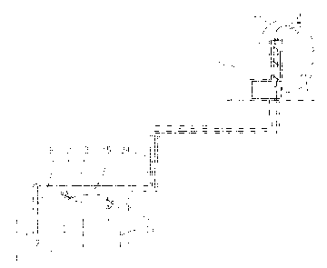
Fig 1 is a schematic illustrating a beverage dispensing cooling system
constructed in
accordance with this invention
Fig 2 is a cross-sectional view of the preferred embodiment of the invention
Detailed Description of the Invention
Fig 1 shows a beverage dispenser cooling system particularly for use in
dispensing beer
on tap. The system includes a storage container such as a beer keg 31
containing beer.
The keg 31 will typically be located within a refrigerated unit 33 such as a
large walk-in
refrigerator. A pressurized tank, usually containing carbon dioxide, beer gas
or
compressed air 39 is connected by line 35 to the interior of keg 33 for
applying pressure
to the beer therein. The contents of the beer keg 31 are connected to the
booster 26 by
line 7 that travels through an insulated trunk line 34. The beer travels
through booster 26
and travels through line 11 faucet and flows to faucet 36. The distance
between the beer
keg 31 and the dispensing tap 36 can be quite far, with the trunk line
extending up to five
hundred feet. To prevent the beer in the trunk line from warming excessively,
a glycol
unit 32 is used. Glycol unit 32 is a conventional assembly, which chills
glycol and
2

CA 02482264 2004-09-23
pumps it through the trunk line 34 to the booster 26 and back. The glycol
travels in
parallel with the beer keeping it cool.
In the particularly advantageous embodiment of the invention illustrated and
noted by the
numerical designation 25, the booster consists of a tank 3, which contains a
reservoir 4
and a heat exchanger 6. The booster is covered with a layer of insulation 18.
The
beverage, usually beer, flows from line 7 into fitting 20 through line 23 to
fitting 12 into
the heat exchanger 6. From the heat exchanger fitting 14 the beer flows
through line 8
into reservoir 4 by way of fitting 15. The beer flaws through the reservoir 4
and exits
from fitting 21 into line 16 and into fitting 17. From fitting 17 the beer
flows to the
faucet by way of line 11. The coolant enters the booster from line 2, which is
attached to
fitting 1. The coolant flows into the booster and is guided around the
reservoirs 4 by fins
5 that are attached to the outside of the reservoir 4. The fins allow for
greater contact
area between the reservoir and the cooling liquid to enhance heat transfer
from the beer to
the liquid. The coolant fills the cavity 26 and surrounds the heat exchanger 6
prior to
entering the heat exchanger 6 through port 10. The coolant travels through the
heat
exchanger 6 through port 13 and flows through line 24 to fitting 19 where it
exits the
booster and returns to the cooling system by way of line 9.
In another particularly advantageous embodiment illustrated in Figure 3 noted
by the
numerical designation 53, the booster consists of a tank 40 with end plates 55
and 54,
which contains a reservoir 46 and a heat exchanger coil 42. The booster is
covered with a
layer of insulation 41 with an outer shell 52. The beverage, usually beer,
flows from line
7, into line 56 and into the heat exchanger coil 42. From the heat exchanger
coil 42 the
beer flows through line 49 into reservoir 46. The beer flows through the
reservoir 46 and
exits through line 48. From line 48 the beer flows to the faucet 36 by way of
line 11.
The coolant enters the booster from line 57. The coolant fills the cavity 51
and flow over
the heat exchanger coil 42 and the reservoir 46 prior to exiting through line
50 and
returning to the cooling system by way of line 9.
It will be apparent that various changes and modifications can be made without
departing
from the scope of the invention as defined in the claims. Thus the shape of
the outer shell
3

CA 02482264 2004-09-23
3 of the Unit may be modified to suit mounting conditions and the type of heat
exchanger
may be modified accordingly.
Various embodiments of the present invention having been thus described in
detail by
way of example, it will be apparent to those skilled in the art that
variations and
modifications may be made without departing from the invention. The invention
includes
all such variations and modifications as fall within the scope of the appended
claims.
4

Dessin représentatif
Une figure unique qui représente un dessin illustrant l'invention.
États administratifs

2024-08-01 : Dans le cadre de la transition vers les Brevets de nouvelle génération (BNG), la base de données sur les brevets canadiens (BDBC) contient désormais un Historique d'événement plus détaillé, qui reproduit le Journal des événements de notre nouvelle solution interne.

Veuillez noter que les événements débutant par « Inactive : » se réfèrent à des événements qui ne sont plus utilisés dans notre nouvelle solution interne.

Pour une meilleure compréhension de l'état de la demande ou brevet qui figure sur cette page, la rubrique Mise en garde , et les descriptions de Brevet , Historique d'événement , Taxes périodiques et Historique des paiements devraient être consultées.

Historique d'événement

Description Date
Demande non rétablie avant l'échéance 2006-12-27
Inactive : Morte - Aucune rép. à lettre officielle 2006-12-27
Réputée abandonnée - omission de répondre à un avis sur les taxes pour le maintien en état 2006-09-25
Demande publiée (accessible au public) 2006-03-23
Inactive : Page couverture publiée 2006-03-22
Inactive : Renseign. sur l'état - Complets dès date d'ent. journ. 2006-02-15
Inactive : Abandon. - Aucune rép. à lettre officielle 2005-12-28
Inactive : CIB en 1re position 2004-12-22
Inactive : Lettre de courtoisie - Preuve 2004-11-16
Demande reçue - nationale ordinaire 2004-11-10
Exigences de dépôt - jugé conforme 2004-11-10
Inactive : Certificat de dépôt - Sans RE (Anglais) 2004-11-10

Historique d'abandonnement

Date d'abandonnement Raison Date de rétablissement
2006-09-25

Historique des taxes

Type de taxes Anniversaire Échéance Date payée
Taxe pour le dépôt - petite 2004-09-23
Titulaires au dossier

Les titulaires actuels et antérieures au dossier sont affichés en ordre alphabétique.

Titulaires actuels au dossier
ICEFLOE TECHNOLOGIES INC.
Titulaires antérieures au dossier
MARKUS HESS
PHIL CARTER
SAM CHIUSOLO
Les propriétaires antérieurs qui ne figurent pas dans la liste des « Propriétaires au dossier » apparaîtront dans d'autres documents au dossier.
Documents

Pour visionner les fichiers sélectionnés, entrer le code reCAPTCHA :


Pour visualiser une image, cliquer sur un lien dans la colonne description du document. Pour télécharger l'image (les images), cliquer l'une ou plusieurs cases à cocher dans la première colonne et ensuite cliquer sur le bouton "Télécharger sélection en format PDF (archive Zip)" ou le bouton "Télécharger sélection (en un fichier PDF fusionné)".

Liste des documents de brevet publiés et non publiés sur la BDBC .

Si vous avez des difficultés à accéder au contenu, veuillez communiquer avec le Centre de services à la clientèle au 1-866-997-1936, ou envoyer un courriel au Centre de service à la clientèle de l'OPIC.


Description du
Document 
Date
(aaaa-mm-jj) 
Nombre de pages   Taille de l'image (Ko) 
Description 2004-09-23 4 200
Abrégé 2004-09-23 1 37
Revendications 2004-09-23 2 45
Dessins 2004-09-23 3 54
Dessin représentatif 2006-02-01 1 8
Page couverture 2006-03-13 2 49
Certificat de dépôt (anglais) 2004-11-10 1 158
Demande de preuve ou de transfert manquant 2005-09-26 1 100
Courtoisie - Lettre d'abandon (lettre du bureau) 2006-02-08 1 166
Rappel de taxe de maintien due 2006-05-24 1 110
Courtoisie - Lettre d'abandon (taxe de maintien en état) 2006-11-20 1 175
Correspondance 2004-11-10 1 27