Sélection de la langue

Search

Sommaire du brevet 2482461 

Énoncé de désistement de responsabilité concernant l'information provenant de tiers

Une partie des informations de ce site Web a été fournie par des sources externes. Le gouvernement du Canada n'assume aucune responsabilité concernant la précision, l'actualité ou la fiabilité des informations fournies par les sources externes. Les utilisateurs qui désirent employer cette information devraient consulter directement la source des informations. Le contenu fourni par les sources externes n'est pas assujetti aux exigences sur les langues officielles, la protection des renseignements personnels et l'accessibilité.

Disponibilité de l'Abrégé et des Revendications

L'apparition de différences dans le texte et l'image des Revendications et de l'Abrégé dépend du moment auquel le document est publié. Les textes des Revendications et de l'Abrégé sont affichés :

  • lorsque la demande peut être examinée par le public;
  • lorsque le brevet est émis (délivrance).
(12) Brevet: (11) CA 2482461
(54) Titre français: RECIPIENT AMELIORE POUR CONTENIR UN PRODUIT
(54) Titre anglais: IMPROVED CONTAINER FOR HOLDING A PRODUCT
Statut: Périmé et au-delà du délai pour l’annulation
Données bibliographiques
(51) Classification internationale des brevets (CIB):
  • A47G 19/14 (2006.01)
  • B65D 23/10 (2006.01)
  • B65D 47/12 (2006.01)
  • B65D 51/18 (2006.01)
(72) Inventeurs :
  • ROHR, ROBERT D. (Etats-Unis d'Amérique)
  • KASTING, THOMAS P. (Etats-Unis d'Amérique)
  • HATHAWAY, JOHN E. (Etats-Unis d'Amérique)
  • TAYLOR, DALE W. (Etats-Unis d'Amérique)
  • MCLELLAND, DOUGLAS M. (Etats-Unis d'Amérique)
(73) Titulaires :
  • RIEKE CORPORATION
(71) Demandeurs :
  • RIEKE CORPORATION (Etats-Unis d'Amérique)
(74) Agent: OSLER, HOSKIN & HARCOURT LLP
(74) Co-agent:
(45) Délivré: 2011-08-02
(86) Date de dépôt PCT: 2003-04-21
(87) Mise à la disponibilité du public: 2003-10-30
Requête d'examen: 2008-01-30
Licence disponible: S.O.
Cédé au domaine public: S.O.
(25) Langue des documents déposés: Anglais

Traité de coopération en matière de brevets (PCT): Oui
(86) Numéro de la demande PCT: PCT/US2003/012198
(87) Numéro de publication internationale PCT: US2003012198
(85) Entrée nationale: 2004-10-18

(30) Données de priorité de la demande:
Numéro de la demande Pays / territoire Date
60/373,939 (Etats-Unis d'Amérique) 2002-04-19

Abrégés

Abrégé français

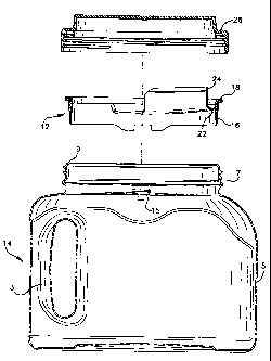
L'invention concerne un récipient conçu pour stocker et distribuer des liquides, qui comporte un corps (14) ayant une partie col annulaire (7) montant qui défini une ouverture de récipient et qui se termine en périphérie annulaire (9) présentant une surface d'étanchéité regardant vers le haut généralement plate et une bride (15) s'étendant vers l'intérieur. Une tête de remplissage séparée (12) comporte une paroi annulaire (16) dont une partie s'étend vers l'intérieur qui définit un bec verseur et, à son extrémité, une lèvre (18) qui s'étend vers l'extérieur. Ladite lèvre comporte une surface d'étanchéité (19) tournée vers le bas. La paroi annulaire comporte un épaulement (17) s'étendant vers l'extérieur en dessous de la lèvre pour se mettre en prise avec le rebord périphérique. La paroi annulaire est conçue pour se loger à l'intérieur de l'ouverture du récipient et son épaulement peut s'encliqueter sur ledit rebord périphérique et créer un joint d'étanchéité entre la surface d'étanchéité périphérique et la surface d'étanchéité de la lèvre. Le récipient comporte également un couvercle amovible (10) qui se met en prise de manière filetée sur le col du récipient.


Abrégé anglais


A container for storing and dispensing fluids includes a container body (14)
having an upwardly extending annular neck portion (7) defining a container
opening an d terminating into an annular rim (9) having a generally flat,
upwardly facing sealing surface and an inwardly extending flange(15). A
separate spout member (12) includes an annular wall (16) having an inwardly
extending portion defining a pour spout and an outwardly extending lip (18) at
one end thereof, wherein the lip includes a downwardly facing sealing surface
(19). The annular wall also includes an outwardly extending shoulder (17)
below the lip for engaging the rim flange, wherein the annular wall is
configured to be received within the container opening and wherein the annular
wall shoulder is capable of being snap-fit over the rim flange to create a
seal between said rime sealing surface and said lip sealing surface. The
container also includes a removable lid (10) that that threadedly engages the
container neck.

Revendications

Note : Les revendications sont présentées dans la langue officielle dans laquelle elles ont été soumises.


12
CLAIMS:
1. A container for storing and dispensing fluids, said container comprising:
a container body defining an interior volume and including an upwardly
extending annular neck portion defining a container opening and terminating
into an
annular rim having a generally flat, upwardly facing sealing surface and an
inwardly
extending flange;
a separate spout member comprising an annular wall having an inwardly
extending portion defining a pour spout and an outwardly extending lip at one
end
thereof, said lip having a downwardly facing sealing surface, said annular
wall having
an outwardly extending shoulder below said lip for engaging said rim flange,
wherein
said annular wall is configured to be received within said container opening
and
wherein said annular wall shoulder is capable of being snap-fit over said rim
flange to
create a seal between said rim sealing surface and said lip sealing surface;
a removable lid having means for engaging said container body;
wherein said neck portion further comprises an inwardly extending tab and said
spout member annular wall further comprises a notch at its lower end, wherein
the
engagement of said tab and said notch permits only a single proper orientation
of said
spout member relative to said container opening.
2. The container of claim 1, wherein said lip further comprises an upwardly
facing
sealing surface and the lid further comprising a downwardly facing annular
sealing
surface, wherein upon engagement of said lid and said container body, said lip
is
compressed between said lid sealing surface and said rim sealing surface to
create an
air-tight seal therebetween.
3. The container of claim 2, wherein said lid further comprises a downwardly

13
extending seal plug which engages the inner surface of said spout member lip
as a
secondary seal between said lid and said spout.
4. The container of claim 1, further comprising a plastic handle assembly
comprising an integrally molded handle and mounting ring wherein said mounting
ring
can be snap fit over said container neck portion.
5. The container of claim 1, wherein said inwardly extending portion of said
spout
member defining a pour spout further includes a trough portion sloping
rearwardly
from said pour spout to provide a drain-back feature where liquid may drain
from said
spout member into said container body.
6. The container of claim 1, wherein said container does not utilize a
separate
sealing gasket to create an air-tight seal between said lid and said spout
member or said
spout member and said container.
7. The container of claim 1, wherein the downwardly facing sealing surface of
the
spout member lip further comprises at least one downwardly-extending annular
sealing
bead to enhance sealing engagement with the rim.
8. A container for storing and dispensing fluids, said container comprising:
a plastic container body defining an interior volume and including an upwardly
extending annular neck portion defining a container opening and terminating
into an
annular rim having a generally flat, upwardly facing sealing surface and an
inwardly
extending flange, said neck portion having outwardly extending spiral threads;
a separate plastic spout member comprising an annular wall having an inwardly
extending portion defining a pour spout and an outwardly extending lip at one
end
thereof, said lip having a downwardly facing sealing surface, said annular
wall having
an outwardly extending shoulder below said lip for engaging said rim flange,
wherein

14
said annular wall is configured to be received within said container opening
and
wherein said annular wall shoulder is capable of being snap-fit over said rim
flange to
create a seal between said rim sealing surface and said lip sealing surface;
a removable plastic lid having spiral grooves for threadedly engaging said
container body; and
wherein said neck portion further comprises an inwardly extending tab and said
spout member annular wall further comprises a notch at its lower end, wherein
the
engagement of said tab and said notch permits only a single proper orientation
of said
spout member relative to said container opening.
9. The container of claim 8, wherein said lip further comprises an upwardly
facing
sealing surface and the lid further comprising a downwardly facing annular
sealing
surface, wherein upon engagement of said lid and said container body, said lip
is
compressed between said lid sealing surface and said rim sealing surface to
create an
air-tight seal therebetween.
10. The container of claim 9, wherein said lid further comprises a downwardly
extending seal plug which engages the inner surface of said spout member lip
as a
secondary seal between said lid and said spout.
11. The container of claim 8, further comprising a plastic handle assembly
comprising an integrally molded handle and mounting ring wherein said mounting
ring
can be snap fit over said container neck portion.
12. The container of claim 8, wherein said inwardly extending portion of said
spout
member defining a pour spout further includes a trough portion sloping
rearwardly
from said pour spout to provide a drain-back feature where liquid may drain
from said
spout member into said container body.

15
13. The container of claim 8, wherein said container does not utilize a
separate
sealing gasket to create an air-tight seal between said lid and said spout
member or said
spout member and said container.
14. The container of claim 8, wherein the downwardly facing sealing surface of
the
spout member lip further comprises at least one downwardly extending annular
sealing
bead to enhance sealing engagement with the rim.

Description

Note : Les descriptions sont présentées dans la langue officielle dans laquelle elles ont été soumises.


CA 02482461 2004-10-18
WO 03/088791 PCT/US03/12198
TITLE OF INVENTION
IMPROVED CONTAINER FOR HOLDING A PRODUCT
FIELD OF INVENTION
[0001 ] The present invention relates in general to containers for storing and
dispensing various
products, and in particular, to portable, hand-held containers for storing and
dispensing viscous
fluids such as paint, cleaning fluids, laundry products, and beverages, to
name a few.
BACKGROUND
[0002] Containers for holding viscous and other fluids are known in the art.
Particularly, with
respect to the paint industry, nearly all generally one-gallon and smaller
paint containers are sold
in cylindrical metal cans having an upper edge with a U-shaped channel that
accepts the annular
protrusion of a high friction metal lid secured by a press fit. This
arrangement has numerous
operational drawbacks that have not been addressed by the industry.
[0003] One such operational drawback is the difficulty in pouring paint from
the can into a tray
or other paint receptacle. The can lip makes a particularly poor spout. When
the paint is poured
from the can, paint must be poured across the U-shaped sealing channel on the
upper edge of the
can. This U-shaped channel inherently retains some of the paint which is
discussed in greater

CA 02482461 2004-10-18
WO 03/088791 PCT/US03/12198
2
detail below. Also, because of the circular shape of the container opening and
the U-shaped
channel, it is difficult to control the pourability of the paint, thus leading
to paint running down
the outside of the container. This is especially true when the container is
full. This greatly adds
to the spilling of sizable quantities of paint.
[0004] Further, in using the container itself as a paint receptacle, users
often dip paint brushes
directly into the container and use the inner edge of the container opening to
wipe excess paint
from the brush. The circular shape of the can opening is particularly
ineffective for wiping a flat
brush clean of excess paint. Further, this also causes paint to gather in the
annular U-shaped
channel.
[0005] As paint collects in the U-shaped peripheral channel, resealing the lid
becomes
particularly messy as the captured paint may splatter when the lid is pounded
back onto the can.
Further, paint in and around the channel can dry and flake, leading to paint
contamination each
time the can is jostled. The pounding of the lid can also damage the sealing
surfaces, which
again can cause the seal to fail. Further, if the paint in the U-shaped
channel dries, it may
prevent the air-tight seal of the lid and the can and allow the paint therein
to dry out or skim
over, thus leading to the waste of the remaining paint. After repeated
opening, pouring, and
closing, the mating surfaces of the can and lid will eventually become fouled
leading to the
failure of the friction seal. Another drawback for metal paint cans is that
while metal cans are
coated to prevent rust, this coating often fails, which leads to rust and
paint contamination.

CA 02482461 2010-11-04
3
[0006] Other such drawbacks include the lack of a locking mechanism that would
prevent the friction lid from popping off if the can is dropped from a height
as little as
one meter, with consequent spilling of the contents widely on the ground. The
lid,
moreover, must be pried off with a tool to gain access to the paint, which
proves a
problem if no tool is available. The prying action, moreover, often damages
the U-
shaped channel lid sealing surface.
[0007] Another drawback in the construction of such metal paint cans is that
the inner
lip of the container opening traps paint as it is poured, thereby preventing
the user from
being able to extract all available paint from the container during pouring or
even if a
brush is used.
[0008] Many efforts have been made to address these and other problems
associated
with the conventional metal paint can. Some prior art improvements remedy to a
degree some of the shortcomings mentioned above, but none, until the present
invention, has effectively solved even a majority of these problems.
[0008a] In accordance with one embodiment of the present invention, there is
provided
a container for storing and dispensing fluids, the container comprising: a
container
body defining an interior volume and including an upwardly extending annular
neck
portion defining a container opening and terminating into an annular rim
having a
generally flat, upwardly facing sealing surface and an inwardly extending
flange; a
separate spout member comprising an annular wall having an inwardly extending
portion defining a pour spout and an outwardly extending lip at one end
thereof, the lip

CA 02482461 2010-11-04
3a
having a downwardly facing sealing surface, the annular wall having an
outwardly
extending shoulder below the lip for engaging the rim flange, wherein the
annular wall
is configured to be received within the container opening and wherein the
annular wall
shoulder is capable of being snap-fit over the rim flange to create a seal
between the
rim sealing surface and the lip sealing surface; a removable lid having means
for
engaging the container body; wherein the neck portion further comprises a
inwardly
extending tab and the spout member annular wall further comprises a notch at
its lower
end, wherein the engagement of the tab and the notch permits only a single
proper
orientation of the spout member relative to the container opening.
[0009] The present invention, on the other hand, synergistically solves nearly
all of the
major problems above-enumerated inherent in the conventional metal paint can.
The
present invention will be more fully described in the following written
description with
reference to the accompanying drawings.
BRIEF DESCRIPTION OF THE SEVERAL VIEWS OF THE DRAWING

CA 02482461 2004-10-18
WO 03/088791 PCT/US03/12198
4
[0010] FIG. 1 is cross-sectional view of the container, the spout, and the lid
during disassembly
of the invention.
[0011 ] FIG. 2 is a perspective view of the spout of FIG. 1.
[0012] FIG. 2A is a top plan view of the spout.
[0013] FIG. 3 is side elevational view of the spout.
[0014] FIG. 4 is a fragmentary, cross-sectional view of the rim portion of the
spout.
[0015] FIG. 5 is a cross-sectional view of the sealing means between the lid,
the spout, and the
container.
[0016] FIG. 6 is perspective view of the container lid.
[0017] FIG. 7 is a bottom perspective view of the spout.
[0018] FIG. 8 is a top plan view of handle component.
[0019] FIG. 9 is a magnified portion of the handle component.
DETAILED DESCRIPTION OF THE INVENTION
[0020] Reference is now made to the drawings. Without limiting scope of the
present invention,
the invention herein is described with regard to its use as a paint container.
However, it is
obvious that the improved container of the present invention could be used for
holding or
dispensing numerous contents including other viscous or powdered products or
any product
requiring a container for dispensing.
[0021] FIG. 1 shows the improved container of this invention used for holding
and dispensing
paint. As shown in FIG. 1, the improved container comprises a container body
14, a spout

CA 02482461 2004-10-18
WO 03/088791 PCT/US03/12198
member 12, and a lid 10. The body 14, spout member 12, and lid 10 are
preferably molded
plastic components, although other suitable materials may be used. However, it
is possible to
integrally mold the spout member 12 and the container body 14 as one piece.
Nevertheless,
utilizing a separately molded spout member 12 enables one to utilize the
entire opening of the
container body when filling the container body and then connecting the spout
member 12 to the
container body 14 for use.
[0022] As shown in FIG. 1, the container 14 includes an integrally molded
handle 3, container
side walls 5, and an upwardly extending neck portion 7. The upwardly extending
neck portion
includes means for threadedly engaging a lid. Preferably, the neck includes
outwardly extending
spiral threads for engaging spiral grooves located in the lid 10. The top
portion of the container
neck 7 includes a circumferential rim 9 having an upwardly facing sealing
surface.
[0023] Referring to FIGS. 1 through 4, spout member 12 comprises an annular
outer wall 16
having a lip 18 extending radially outwardly past the container rim 9 and
nearing the root of the
thread. The lip 18 further includes a downwardly extending flange 19 that will
run in close
proximity to the container wall. Flange 19 is designed such that its outside
diameter is
coincidental with the inner thread diameter on the neck portion. Thus, the
engagement between
the spout member 12 and the container produces a flush or nearly flush
connection with respect
the exterior thereof. As explained below, lip 18 and flange 19 provide a
second sealing means to
be employed once the lid 10 is securely fitted to the container 14.

CA 02482461 2004-10-18
WO 03/088791 PCT/US03/12198
6
[0024] As best shown in FIG. 4, a groove is defined by flange 19, lip 18, and
outer wall 16 to
permit the receipt of the container rim 9 during engagement between the spout
and container.
Preferably, outer wall 16 further comprises a shoulder 17 within the groove to
permit the snap-fit
of the container rim 9 which has a corresponding inwardly extending flange 15.
Such a snap-fit
construction permits the downwardly-facing sealing surface of the spout member
lip 18 to
confront the upwardly-facing sealing surface of the rim 9 to creating a liquid-
tight seal
therebetween. Therefore, upon pouring the contents of the container, the
liquid will not escape
between the spout member and container sealing surfaces and properly exit the
container over
spout/paint return structure 20.
[0025] The downwardly facing sealing surface located on the underside of the
lip 18 may also
include a sealing member located within the groove to assist in sealing the
spout 12 with respect
to the container 14. FIG. 5 shows the lip 18 having at least one annular seal
bead 21. While the
preferred embodiment utilizes a pair of seal beads, it is clear that any
number of seal beads may
be used. The seal beads may form part of the sealing system in cooperation
with the lid and
container opening.
[0026] The spout/paint return structure 20, shown best in FIGS. 2, 2A, and 3,
comprises a
rearwardly sloping trough 22, sloping downwardly from left to right with
respect to FIG. 3,
which permits paint therein to flow into the container 14 by gravity when the
container is in the
upright position. Preferably, the trough 22 extends over only a portion of the
inner
circumference of the spout and only extends partially radially inwardly, such
as in the crescent

CA 02482461 2004-10-18
WO 03/088791 PCT/US03/12198
7
shape shown in the drawings. Extending upwardly from trough 22 is wall 24
which extends
above lip 18 to permit the pouring of paint at an angle that prevents paint
contact with lip 18
during pouring. The top of wall 24 curves and a downwardly extending wall
portion 21 extends
through the spout opening. The area located between the front and rear
portions of the wall 24
permits paint to gradually gather therein during pouring to create a
controlled flow of paint from
the container over the front portion of the wall 24.
[0027] Spout wall 16 also includes at least one notch 13 formed therein which
engages a
protrusion 15 extending from the container 14 so as to properly orient the
spout 12 with respect
to the container 14 and prevent the rotation of the spout 12 when it is set
within the container 14.
Further as see in FIG. 7, the spout wall 16 is reinforced adjacent notch 13 by
at least one
stabilizer 32 which provides additional strength to the spout wall 16 to
prevent the spout wall 16
from flexing and permitting the spout to easily rotate within the container.
Further, spout 12 also
includes large radii 30, best shown in FIG. 2A, in the corners of the
spout/paint return structure
20 to reduce stress risers in the molded part and provide additional pour
control by the end user.
Flange 19 may also include another flange 33 which more positively registers
the spout into the
container opening.
[0028] As shown in FIG. 4, the lip 18 of spout 12 is configured to snap-fit
with the annular rim 9
of container 14. The assembly is best shown in FIG. 5 wherein outer wall 16
fits within the
container opening and lip 18 snap-fits over the annular rim 9 of the container
to fix and seal the
spout 12 within the container opening. The lid 10 is configured to include a
downwardly facing

CA 02482461 2004-10-18
WO 03/088791 PCT/US03/12198
8
sealing surface 26 which engages the upwardly facing sealing surface of lip 18
to compress lip
18 between the lid sealing surface 26 and the rim sealing surface as the lid
threadedly engages
the container 14. Lid 10 freely raises above lip 18 when the lid is threadedly
disengaged from
the container so as not to disrupt the engagement between the spout 12 and the
container 14.
[0029] The lid 10 also includes a downwardly extending annular plug seal 37.
The plug seal 37
slidably engages the inner diameter of the lip 18 of the spout 12 as an
alternate seal between the
lid 10 and the spout 12. The lid 10 further includes a radial seal shoulder 37
designed to place
the outside diameter of the spout 12 under radial compression to improve the
seal between the
spout/lid and spout/container interfaces. The lid 10 may further include a
concentrator step 39 to
work in conjunction with the seal beads of the spout. The concentrator focuses
axial loading of
the lid into the spout seal beads which in turn bear down onto the bottle
opening land surface of
the rim during threaded engagement between the lid and the container opening.
The lid also
includes serrations/ribs 7 to the top portion of the lid to provide an
improved surface for capping
equipment while reducing the visibility of "rubs" or scrapes in the event the
capping chucks spin
against the lid.
[0030] The container assembly may also include a one-piece molded handle,
shown in FIG. 8,
which can be fitted over the neck of the container opening. The one-piece
handle includes an
integrally molded handle ring 42 and a handle 44. The handle is molded wherein
the handle 44
is attached to the handle ring 42 along a handle retainer portion 46. The
handle 44 includes a
recess 40 to shroud any "sharps" left after the handle retainer 46 is broken.
Such a recess 40 will

CA 02482461 2004-10-18
WO 03/088791 PCT/US03/12198
9
minimize the possibility of any sharps being felt by the consumer while hand
carrying the
product. The handle further includes a series of bumps 48 to the inside of the
handle ring 42.
This provides reduced contact area with the ring's "inside diameter" easing
assembly and
allowing the consumer to reposition the handle as desired while providing the
relationships
necessary for proper handle retention on the bottle.
[0031 ] As indicated above, by employing at least one sealing bead located on
the downwardly
facing sealing surface of the spout member lip, the sealing bead works in
combination with a
properly placed lid component. When in proper assembly, the spout and lid will
be in vertical
compression against the rim of the container creating a secure seal to contain
the product within
the container.
[0032] The invention has been described with reference to the preferred
embodiment.
Obviously, modifications and alternations will occur to others upon a reading
and understanding
of this specification. The claims as follows are intended to include all
modifications and
alterations insofar as they come within the scope of the claim or the
equivalent thereof.

Dessin représentatif
Une figure unique qui représente un dessin illustrant l'invention.
États administratifs

2024-08-01 : Dans le cadre de la transition vers les Brevets de nouvelle génération (BNG), la base de données sur les brevets canadiens (BDBC) contient désormais un Historique d'événement plus détaillé, qui reproduit le Journal des événements de notre nouvelle solution interne.

Veuillez noter que les événements débutant par « Inactive : » se réfèrent à des événements qui ne sont plus utilisés dans notre nouvelle solution interne.

Pour une meilleure compréhension de l'état de la demande ou brevet qui figure sur cette page, la rubrique Mise en garde , et les descriptions de Brevet , Historique d'événement , Taxes périodiques et Historique des paiements devraient être consultées.

Historique d'événement

Description Date
Le délai pour l'annulation est expiré 2019-04-23
Lettre envoyée 2018-04-23
Requête visant le maintien en état reçue 2017-04-03
Requête visant le maintien en état reçue 2016-04-06
Requête visant le maintien en état reçue 2013-04-10
Accordé par délivrance 2011-08-02
Inactive : Page couverture publiée 2011-08-01
Préoctroi 2011-05-18
Inactive : Taxe finale reçue 2011-05-18
Un avis d'acceptation est envoyé 2011-03-25
Lettre envoyée 2011-03-25
Un avis d'acceptation est envoyé 2011-03-25
Inactive : Approuvée aux fins d'acceptation (AFA) 2011-03-18
Modification reçue - modification volontaire 2010-11-04
Inactive : Dem. de l'examinateur par.30(2) Règles 2010-05-20
Modification reçue - modification volontaire 2008-05-26
Lettre envoyée 2008-04-15
Requête d'examen reçue 2008-01-30
Exigences pour une requête d'examen - jugée conforme 2008-01-30
Toutes les exigences pour l'examen - jugée conforme 2008-01-30
Inactive : CIB de MCD 2006-03-12
Lettre envoyée 2005-09-23
Inactive : Transfert individuel 2005-06-28
Demande de correction du demandeur reçue 2005-06-28
Inactive : Page couverture publiée 2005-01-06
Inactive : Lettre de courtoisie - Preuve 2005-01-04
Inactive : Lettre de courtoisie - Preuve 2004-12-29
Inactive : Notice - Entrée phase nat. - Pas de RE 2004-12-23
Demande reçue - PCT 2004-11-12
Exigences pour l'entrée dans la phase nationale - jugée conforme 2004-10-18
Demande publiée (accessible au public) 2003-10-30

Historique d'abandonnement

Il n'y a pas d'historique d'abandonnement

Taxes périodiques

Le dernier paiement a été reçu le 2011-03-10

Avis : Si le paiement en totalité n'a pas été reçu au plus tard à la date indiquée, une taxe supplémentaire peut être imposée, soit une des taxes suivantes :

  • taxe de rétablissement ;
  • taxe pour paiement en souffrance ; ou
  • taxe additionnelle pour le renversement d'une péremption réputée.

Les taxes sur les brevets sont ajustées au 1er janvier de chaque année. Les montants ci-dessus sont les montants actuels s'ils sont reçus au plus tard le 31 décembre de l'année en cours.
Veuillez vous référer à la page web des taxes sur les brevets de l'OPIC pour voir tous les montants actuels des taxes.

Titulaires au dossier

Les titulaires actuels et antérieures au dossier sont affichés en ordre alphabétique.

Titulaires actuels au dossier
RIEKE CORPORATION
Titulaires antérieures au dossier
DALE W. TAYLOR
DOUGLAS M. MCLELLAND
JOHN E. HATHAWAY
ROBERT D. ROHR
THOMAS P. KASTING
Les propriétaires antérieurs qui ne figurent pas dans la liste des « Propriétaires au dossier » apparaîtront dans d'autres documents au dossier.
Documents

Pour visionner les fichiers sélectionnés, entrer le code reCAPTCHA :


Pour visualiser une image, cliquer sur un lien dans la colonne description du document. Pour télécharger l'image (les images), cliquer l'une ou plusieurs cases à cocher dans la première colonne et ensuite cliquer sur le bouton "Télécharger sélection en format PDF (archive Zip)" ou le bouton "Télécharger sélection (en un fichier PDF fusionné)".

Liste des documents de brevet publiés et non publiés sur la BDBC .

Si vous avez des difficultés à accéder au contenu, veuillez communiquer avec le Centre de services à la clientèle au 1-866-997-1936, ou envoyer un courriel au Centre de service à la clientèle de l'OPIC.


Description du
Document 
Date
(aaaa-mm-jj) 
Nombre de pages   Taille de l'image (Ko) 
Description 2004-10-17 9 321
Dessins 2004-10-17 5 109
Revendications 2004-10-17 5 139
Dessin représentatif 2004-10-17 1 20
Abrégé 2004-10-17 2 79
Description 2010-11-03 10 364
Revendications 2010-11-03 4 145
Dessin représentatif 2011-06-27 1 11
Rappel de taxe de maintien due 2004-12-22 1 109
Avis d'entree dans la phase nationale 2004-12-22 1 192
Courtoisie - Certificat d'enregistrement (document(s) connexe(s)) 2005-09-22 1 104
Rappel - requête d'examen 2007-12-23 1 118
Accusé de réception de la requête d'examen 2008-04-14 1 177
Avis du commissaire - Demande jugée acceptable 2011-03-24 1 163
Avis concernant la taxe de maintien 2018-06-03 1 178
PCT 2004-10-17 5 227
Correspondance 2004-12-22 1 26
Correspondance 2004-12-28 1 26
Taxes 2005-04-13 1 41
Correspondance 2005-06-27 1 52
Taxes 2006-04-11 1 41
Taxes 2007-03-11 1 48
Taxes 2008-04-06 1 45
Taxes 2009-04-05 1 71
Taxes 2010-03-31 1 55
Taxes 2011-03-09 1 53
Correspondance 2011-05-17 1 53
Taxes 2012-04-10 1 53
Taxes 2013-04-09 1 46
Paiement de taxe périodique 2016-04-05 1 43
Paiement de taxe périodique 2017-04-02 1 41