Note : Les descriptions sont présentées dans la langue officielle dans laquelle elles ont été soumises.
CA 02483381 2004-10-22
WO 03/091652 PCT/US03/12474
CAMOUFLAGE COVERING
BACKGROUND INFORMATION
Protecting a structure such as a building or a vehicle from detection often
is desirable. Many means of camouflaging objects are known in the fields of
surveillance and wildlife observation.
Some of these involve protection that is built-in to the structure in
question. For example, GB 565,238 describes a process and means for coating
objects for the purpose of camouflage. A paint-like coating is applied which
protects the objects from detection in the visible and infrared (IR) portions
of the
electromagnetic spectrum. This type of built-in camouflages is effective
against
visual detection only in areas with natural colors) that match closely those
of
the camouflage system. For example, a temporary building painted with a
sand-colored coating would be camouflaged in desert situations but would stand
out against a jungle environment; thus, the structure would require repainting
when moved from one environment to another.
Other means involve removable protection such as, e.g., a camouflage
net. In this respect, U.S. Pat. No. 5,549,938 describes flexible magnetic
panels
having camouflage patterns provided thereon. The panels are designed to
magnetically attach to steel surfaces such as the panels of a vehicle,
reducing
the chance of visual detection of the vehicle. Such removable camouflage
panels are convenient to apply or remove but are designed to protect an object
only against visual detection. Surveillance equipment or animals with the
ability
CA 02483381 2004-10-22
WO 03/091652 PCT/US03/12474
to detect UV or IR emissions, for example, can detect the presence of an
object
protected by such panels.
Yet another means is a semi-permanent type, such as a demountable
screen for shielding. In this respect, U.S. Pat. No. 4,560,595 discloses a
camouflage sheet material designed to have thermal emission characteristics
which match closely those of the natural environment in which the camouflage
material is to be used. The sheet can protect objects against detection in the
thermal IR wavelength ranges and is also adapted to provide camouflage in the
ultraviolet (U~, visible and photographic IR wavelengths. The camouflage
material may be attached to a supporting web by means of an adhesive or by
mechanical means such as clamps or sewing. This type of sheet material
cannot be applied easily and quickly to a structure because it first must be
attached to a supporting web and then somehow attached to a structure to be
protected. If the structure is, e.g., a vehicle, the sheet must be securely
attached to the vehicle to prevent it from releasing when the vehicle moves.
It is often important that a camouflage covering be robust against severe
weather and remain in place and undamaged for extended periods of time.
A brief discussion will now be given of sensing methods available for
detecting objects, and of protection means available to protect against
detection.
Detection in the visible portion of the spectrum is used, both by land-
based surveillance systems or individuals and by satellites, to detect the
presence of objects. The nature of an area surrounding an object dictates the
type of camouflage cover required to protect against visual detection. The
2
CA 02483381 2004-10-22
WO 03/091652 PCT/US03/12474
earlier examples of desert and jungle situations would require sand-colored
and
patterned green coverings respectively. It is often desirable that the color
of a
surface change rapidly for a camouflage system to adapt to new surroundings.
Similarly, the surtace texture of an object can affect whether an object is
easy or difficult to detect visibly. Surface profiling can be used to protect
objects
against detection by aerial imaging. If a surface of an object is uneven,
light
scatters unevenly (i.e., differently from different parts) thus breaking up
the lines
of the object and rendering it difficult to detect. Shadows created by an
object
also can be minimized by suitable use of uneven surface profiles.
The shape of objects also can be important. Many vehicles and
buildings are designed to have stealthy shapes comprising multiple oriented
flat
panels which are not easily detected. An irregularity in the shape of a
surface
can render the surface susceptible to detection. For example, a bolt
protruding
from an otherwise smooth surface can give a strong signal on imaging
equipment in certain parts of the electromagnetic spectrum.
UV sensors can detect an object that transmits a UV signature
substantially different from that of its surroundings. UV pigments can be used
to
give the surface of an object the correct properties such that it cannot
easily be
observed by UV sensors.
In an analogous manner, IR signatures of objects can make them easy to
detect, and pigments again can be used to give an object apparently similar IR
properties to that of its surroundings. Alternatively, reflective metallic
layers can
be incorporated beneath a colored but IR transmissive polymer (e.g., poly-
ethylene or polypropylene) film.
3
CA 02483381 2004-10-22
WO 03/091652 PCT/US03/12474
Thermal imaging can be used to detect objects via the (IR) heat that they
produce. Metallized particles or fibers (scrim) incorporated into a material,
or a
metallized film applied over the same, can be used to reflect heat produced in
the object back toward the source so that the external surface of the object
is
not seen as producing a great deal of heat. An example of a situation in which
this effect might be useful is in protecting a moving vehicle from detection
while
the engine of the vehicle radiates a large amount of heat.
In addition, or alternatively, phase change materials (PCMs) can be used
to absorb heat from hot spots of objects. For instance, a PCM which operates
at a high temperature could be used to smooth out the heat signature of a
boiler
housing.
Radar is also used in surveillance systems to detect objects. To avoid
detection by this method, radar-absorbing materials (RAMs) can be used in
camouflage coverings.
Absorption of acoustic signals also often is desirable. Materials such as
high density foam, rubber and ceramics can be effective for this purpose.
Providing a camouflage covering that can be applied quickly, easily and
securely to an object to be protected and that can provide protection against
a
range of detection means remains desirable.
SUMMARY OF THE INVENTION
Briefly, the present invention provides including at least one sheet having
a plurality of components, each component being capable of protecting a
structure against detection by at least one sensing method. The sheet has an
4
CA 02483381 2004-10-22
WO 03/091652 PCT/US03/12474
adhesive exterior surface whereby it can adhere to the structure and, opposite
the adhesive surface, an exterior surface with an uneven surface profile.
A backing sheet can be removably attached to the adhesive surface such
that the backing sheet can be removed to expose the adhesive surface. The
covering then can be applied directly to a surface of an object to be
protected.
The covering subsequently can be removed from the object without damaging it.
The covering can include UV and/or IR pigments. Also, it can include a
metallized scrim, the threads of which could be metallized with AI, Ni, Cu, or
chrome.
The covering can include one or more radio absorbing material such as
carbonyl iron, aramid fibers, ferrites, or carbon loaded foams. Suitable
classes
of RAMs include Salisbury screens, Jaumann absorbers, circuit analog
absorbers, magnetic RAM and Hybrid RAM systems. Additionally, the covering
can include a flexible soft-magnetic thin film which can act as both a radar
absorber and an IR reflector. Suitable examples of magnetic films include
alloys
of Co, Fe, Si, Mo, and Bo and/or Co, Zr, and Nb. One component of the
covering could suitably comprise a PCM such as hydrated AIC13, hydrated
MgCl2, or Glauber's salt.
The covering also can suitably include an acoustic absorber made of a
material as described previously.
The sheet preferably is flexible so that it can be rolled up for easy
transportation, storage, application and manipulation.
The covering can include a plurality of layers each provides protection
against detection by at least one sensing method. One of the layers can be a
5
CA 02483381 2004-10-22
WO 03/091652 PCT/US03/12474
paint layer applied directly to the object to be protected or to a surface of
the
covering itself. Suitably, at least one of the layers of such a multilayer
covering
can be removably adhered to an adjacent layer. Adhesive layers could be
provided between each of the layers. This convertibility/removability feature
of
might be useful in situations where altering the visual appearance of a
covering
while leaving the other camouflage functions of the covering unchanged is
required. For example, a sand-colored upper layer could be removed from a
covering at a time when the covering is no longer to be used in a desert
environment but is instead to be used in a vegetated area. This can eliminate
the need to remove the entire covering, which may still be in good condition
after extended use; instead, the outer layer could be peeled off and replaced
by
a similar outer layer of a different pattern or color to suit the new
environment.
According to a second aspect, the present invention provides a method
for protecting a structure. The method includes applying to a surface of the
structure a covering having any combination of the features as set out above
in
relation to the first aspect of the invention.
According to a third aspect, the present invention provides a camouflage
system that includes first and second coverings as just described with the
second covering being removably adhered to the first.
In a fourth aspect, the present invention provides a kit for camouflaging
surfaces that includes a first elongate sheet patterned with two zones, the
zones
having different appearances, each zone extending along a relatively long
dimension of the sheet, wherein one side of each zone runs continuously along
a respective side of the sheet, and the other side of each zone is delimited
by a
6
CA 02483381 2004-10-22
WO 03/091652 PCT/US03/12474
boundary extending along the relatively long dimension of the sheet in a
generally undulating form. All regions of the sheet on one side of the
boundary
form a zone of a first appearance and all regions of the sheet on the other
side
of the boundary form a zone of a second appearance; and a second elongate
sheet having a continuous field of the first appearance within which are
disposed isolated regions of the second appearance. The two sheets can be
subdivided with resulting sections from each being capable of being joined so
as to form a camouflage pattern.
In yet another aspect, the present invention provides a method for
forming a covering for application on surfaces of a structure. The method
includes digitally printing a non-repeating camouflage pattern onto a covering
having any one or more of the features set out above.
BRIEF DESCRIPTION OF THE DRAWINGS
In the accompanying drawings, like reference numerals refer to like
parts.
FIG. 1 shows a cross section of a camouflage covering according to the
present invention which includes several components.
FIG. 2 shows a camouflage covering that includes an adhesive surface
with a removable backing sheet.
FIG. 3 shows an unprotected building exposed to light.
FIG. 4 shows a building protected by a camouflage covering being
exposed to light.
FIG. 5 shows the heat signature of an unprotected boiler house.
7
CA 02483381 2004-10-22
WO 03/091652 PCT/US03/12474
FIG. 6 shows the heat signature of a boiler house protected by a
covering comprising a PCM and metallized scrim.
FIG. 7 shows two sheets including multi-zone patterns in accordance
with the fourth aspect of the invention described above.
S FIG. 8 shows portions cut from the sheets from FIG. 7.
FIG. 9 shows the combination resulting when the strips from FIG. 8 are
combined.
DETAILED DESCRIPTION
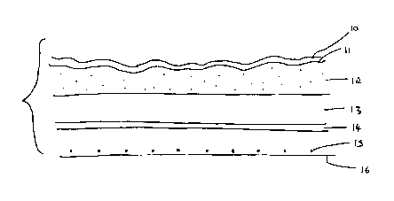
FIG. 1 shows covering 1 with several components 10-15, each of which
can provide protection against detection for a covered object. Any combination
of the components shown may be used in a camouflage covering; other compo-
nents having similar or different camouflage properties can be incorporated in
a
similar manner.
Component 10 is a painted or printed layer. The layer may be patterned,
and is of one or more colors that provide limited contrast with the
surroundings
of the structure to which covering 1 is to be applied. The pattern of the
painted
or printed layer is intended to make difficult visual detection of a structure
within
a pre-decided (visible) wavelength range.
Further layers of paint or adhesive printed sheets may be applied to layer
10 to change the color of the covering to match different surroundings. Layer
10
may be digitally printed to give a camouflage color and pattern most suited to
a
specific operational environment. The color and pattern could be generated
from a set of real background images by, for example, analysis of such images
8
CA 02483381 2004-10-22
WO 03/091652 PCT/US03/12474
to establish a form of pattern that has low contrast against the background
and
then forming images of that form by means of a suitable algorithm or pseudo-
random procedure. Covering sheets could be individually printed for disguising
specific objects against their backgrounds. With digital printing, sheets can
be
printed with a non-repeating pattern, which can make the sheets less prone to
detection.
Component 11 is a surface which has been embossed to give a profiled
structure. The profiled structure has a degree of surface relief and/or
unevenness which acts to scatter light and other electromagnetic wavelengths
from the covering to break up the outer surface of a structure to which the
covering is to be applied. Embossed surface 11 is useful in protecting a
structure against detection by visible (aerial), IR and RADAR imaging.
The dimensions of the indentations determine the frequencies of
radiation against which the covering can best protect. Preferably, the
1 S dimensions of the features of the surface profile - the depth of grooves,
the
height of protrusions, and/or the spacing between them - are approximately
half
the wavelength of the radiation against which protection is desired. If, for
example, protection against IR detection is desired, the features of the
surface
relief should be of the order of 0.4 to 500 Nm, e.g., 200 Nm.
Additionally, the surface profile can be used to disrupt the shadow of a
structure. For this purpose the dimensions of the features of the surface
relief
should be of a scale of approximately 1 to 50 cm. The relief could be provided
by an array of comb-like projections from the surface of the covering.
9
CA 02483381 2004-10-22
WO 03/091652 PCT/US03/12474
To deflect radar, the surface indentations should preferably be regularly
shaped, and around 1 mm deep. Again, preferably the dimensions of the
features of surface relief are approximately half the wavelength.
Component 12 contains UV and/or IR pigments which provide the
surface of a protected structure with UV and/or IR signatures resembling those
of its surroundings, thus protecting the structure against detection by UV
and/or
IR sensors. Alternatively, a metallic film positioned beneath a pigmented, IR
transmissive film can be used to the same effect.
Component 13 includes a PCM which preferably changes phase at a
working temperature in such a way that the phase change is endothermic upon
increasing temperature. In this way, the PCM acts as a thermal buffer. Prefer-
ably, the working temperature of the material is around the upper or lower
limit
of the expected ambient temperature at the location where the covering is to
be
used. Layer 13 acts to absorb heat when it reaches the phase change temper-
ature of the PCM, thus smoothing out the heat signature of structures
containing
heat-producing objects.
Component 14 is a metal film which assists heat dissipation. This also
acts to smooth the heat signature of the structure being protected, by
reflecting
heat towards the source and thus preventing the external surface of the
structure from producing a localized heat signature.
The points 15 shown in FIG. 1 represent the cross sections of metallized
threads, or scrim, woven into covering 1. When a covering comprising scrim is
applied over an outer surface of a structure, an effect of the scrim is to
produce
a Faraday cage. The inside of the structure must be electrically uncharged,
CA 02483381 2004-10-22
WO 03/091652 PCT/US03/12474
such that any charge placed inside the cage is cancelled by an equal and
opposite charge spread across the exterior of the cage. A structure protected
by a scrim covering is therefore difficult to detect by means of
electromagnetic
imaging in that it prevents transmission of EM waves in or out of the
structure.
In addition the scrim should protect the structure from an electromagnetic
pulse.
The scrim also acts to reflect heat produced within the structure.
Such metallized threads can be produced by electrocatalytic deposition .
in which a thin layer of Cu or AI is deposited onto the surface of a fiber. As
discussed above, metallized particles or a metallized film can be used in
place
of scrim.
An adhesive layer 16 is shown on an exterior surface of covering 1. This
allows covering 1 to be applied quickly and easily to an object to be
protected.
The adhesive 16 could be covered by a removable backing sheet to protect the
adhesive layer prior to application of the covering.
In FIG. 2, layer 17 is a backing sheet removably adhered to covering 1.
This backing sheet can be peeled off for covering 1 to be adhesively applied
to
the surface of a structure/object.
FIG. 3 shows a building 20, such as a temporary structure erected from a
flat-pack, unprotected by any camouflage covering. Building 20 is exposed to
light from, say, the sun or a spotlight. The surface 22 of the building, which
is
shaded from the light, appears considerably darker than surface 21, which is
directly exposed to the light source. This contrast in shadow allows building
20
to be detected easily by an equipment or individual scanning in the visible
range
of the spectrum.
11
CA 02483381 2004-10-22
WO 03/091652 PCT/US03/12474
To reduce this susceptibility, use can be made of embossed surfaces (11
in FIG. 1 ) which act to scatter light and create shadows on surfaces of the
structure to be protected. The result of this effect is shown in FIG. 4 where
it
can be seen that surface 21 appears darker than in FIG. 3, and surface 22
appears relatively lighter.
FIG. 5 shows a boiler house 30 without any camouflage covering. A
boiler is contained within the structure, and its location is shown at 31.
Heat
emitted by the boiler produces a heat signature as represented by contour
lines
32. The source of the heat can clearly be seen, and this signature of the
boiler
house is in sharp contrast to the heat signature of the natural environment in
which the boiler house is situated. This renders the boiler house susceptible
to
detection by heat sensing surveillance equipment.
If a covering including a PCM (shown as 13 in FIG. 1) is used to protect
the boiler house, the heat signature of the structure changes; FIG. 6 shows
this
smoother signature. A small heat source positioned at 31 still can be seen
within boiler house 30, but the contour lines 33 are considerably more sepa-
rated from one another than before, which makes detection by IR scanning
methods less likely.
A high performance thermal insulating layer also can be included in the
covering. Suitable materials for this layer would include glass fibre,
microfiber
or aerogels.
The inclusion in a camouflage covering including more than one of the
components discussed above provides simultaneous protection from detection
by multiple sensing methods. In addition, an adhesive surface allows the
12
CA 02483381 2004-10-22
WO 03/091652 PCT/US03/12474
covering to be applied quickly and easily to a structure. It may also be
adapted
such that, upon removal of the covering, the underlying structure is undamaged
and may subsequently be covered by a different covering. This feature would
be useful in circumstances where structures are required to be frequently
erected and dismantled.
The covering is conveniently in sheet form. The sheet may be formed of
one or more sub-sheets laminated or adhered to one another. The sub-sheets
may be bonded together either permanently or releasably by an adhesive layer
carried by one or both of the sub-sheets.
In a preferred arrangement, one such sub-sheet includes one or more
components that can inhibit detection by a sensing means such as radar or IR
scanning (the effectiveness of which is relatively independent of the
environment in which the covering may be deployed) and another includes one
or more components that can inhibit detection by a sensing means such as
visible observation (the effectiveness of which is relatively dependent on the
environment in which the covering is to be deployed). With this system, the
former sub-sheet can be applied to a structure for protection in any
environment. A number of variations of the latter sub-sheet can be available
for
use in corresponding environments, e.g., desert, temperate, jungle, snow, etc.
The latter sub-sheet is preferably deployed on the outside of the covering,
further from the outer surface of the object to be protected so that its
surface is
exposed once the sheet has been deployed. Three or more sub-sheets, each
with respective protective properties can be used.
J
13
CA 02483381 2004-10-22
WO 03/091652 PCT/US03/12474
The inner and outer sheets each can be provided with an adhesive layer
on one of their major surfaces. In the case of the inner sheet, this can be
used
for attaching it to a structure that is to be protected; in the case of the
outer
sheet, this can be used for attaching it either to such a structure or to an
inner
sheet that has previously been adhered to the structure. The adhesive layer of
the inner sheet could employ a permanent adhesive while the adhesive layer of
the outer sheet could employ a releasable adhesive, or the adhesive layer of
the
inner sheet could be more adherent than that of the outer sheet. These
configurations make it easier to apply an inner sheet to a structure and then
change its appearance to match a certain environment by removing a previously
deployed outer sheet and replacing it with another. A multiplicity of such
inner
sheets can be used, one on top of another, to provide additional protection.
The sheets) can be fitted with a removable protective sheet over the for
the reasons stated previously.
The components that help to provide protection can be formed into a
sheet or layer, embedded into a sheet, and/or sandwiched between two sheets
depending on the nature of the components.
The sheets) can be formed from a polymer such as PVC, PVF,
polypropylene, polyethylene, silicones, polysulfones, polyesters, and the
like.
FIG. 7 shows a pair of sheets of a covering. The sheets are relatively
long in one dimension and may be rolled up for storage and easy transportation
in the same way as conventional wall paper. Each sheet, 70 and 75, is
patterned with two zones. Each zone has a single color or multicolored
pattern;
14
CA 02483381 2004-10-22
WO 03/091652 PCT/US03/12474
for example, zones of the first type may be colored green, and zones of the
second type colored brown.
Sheet 70 is patterned such that zone 72 extends along the longer
dimension of the sheet. One side of zone 72 runs continuously along one side
of sheet 70; the other side of zone 72 is delimited by boundary 73 extending
along the longer dimension of the sheet in a generally undulating form. All
regions 71 of the sheet on the other side of boundary 73 form a zone of the
second type. Sheet 75 has a field 76 formed by a zone of the second type on
which are disposed isolated zones 78 of the first type, shown as approximately
oval.
Referring now to FIG. 8, if portions of sheets 70 and 75 are applied in a
particular way to an object to be camouflaged, then a useful pattern can be
obtained. Strips 80 and 82 of sheet 70 are applied along opposite sides of a
surface of the object so that the zones 72 of the first type of those strips
run
along the edges of that surface. The region between those strips is filled
with
strip 81 from sheet 75. The arrangement of strips 80, 81 and 82 is shown in
FIG. 8, and FIG. 9 shows an overall pattern resulting from such a combination.
The effect of such a pattern is that the sides of the surface along which
the zones of the first type (strips 80 and 82 from FIG. 8) run can be
camouflaged
especially effectively. For example, if the color and/or pattern of the first
zone of
is of low contrast with the surroundings of the object, then the presence of a
zone of the first type continuously along two sides of the object is likely to
make
it more difficult to detect. For example, in a woodland setting, if the zone
of the
CA 02483381 2004-10-22
WO 03/091652 PCT/US03/12474
first type is dark (e.g., black), then it can visually disrupt the edges of
the object
by causing confusion with nearby shadows.
A preferred configuration is shown in FIG. 9 in which the wavy boundary
73 (from FIG. 7) periodically defines wider regions of the zone of the first
type,
and these regions are located at the corners of the surface of the object on
which the sheets are applied. This can emphasize the visual disruption at the
corners of the object.
In this way, large surfaces can be covered with an effective camouflage
layer without the necessity of large individual sheets. Large sheets are
difficult
and cumbersome to manipulate and store.
Sheets 70 and 75 could suitably be coated on the side opposite the
patterned side with an adhesive layer, and the adhesive layer could
conveniently be covered by a removable backing sheet. This allows for simple
and quick application of the sheets in any desired arrangement.
Each individual feature has been described in isolation, but any
combination of two or more such features also is to be considered as having
been disclosed, to the extent that such features or combinations are capable
of
being carried out based on the present specification as a whole in the light
of
the common general knowledge of a person skilled in the art, irrespective of
whether such features or combinations of features solve any problems
disclosed herein. Aspects of the present invention may consist of any such
individual feature or combination of features.
16