Note : Les descriptions sont présentées dans la langue officielle dans laquelle elles ont été soumises.
CA 02483521 2004-11-O1
1
TITLE OF THE INVENTION:
Slip Crrip Device
FIELD OF THE INVENTION
The present invention relates to a slip grip device, which permits a cord to
be
adjusted to any given position or Length, while releasing the cord at a pre-
determined
pressure, thus ensuring safety in the event that the cord is inadvertently
caught.
BACKGROUND OF THE INVENTION
Cords to wear jewellery, for clothing, to keep glasses on, in sports equipment
and
in industry are commonplace. However, in many cases these cords are neither
adjustable
nor safe for the user. Most require multiple steps to attach. Many are made of
in
expensive metal which can cause allergic problems. If catches are made from
semi-
precious metals, they are too expensive for regular use. Most metal catches
can break too
2 5 easily and repair is diffcult or expensive: Alternatively, there are some
sorts of plastic
catches available. They are usually bulky, leave loose ends, have moving parts
and
assembly requires multiple steps and adhesives.
The jewellery industry mainly relies upon hand-tied knots to provide an
affordable,
2 0 adjustable, aesthetic method of completing the cords. There are many
problems associated
with the use of knots. Consistency is virtually impossible. Tying of the knots
is a
physically burdensome chore. If the knots are too tight, it can be very
difficult to adjust
the length of the cord. It will grip, but will not slip. If the knots are too
loose, they will
slip, but not grip. Furthermore, they unravel and come undone. Long-term use
of knots
2 5 causes fraying of the cord. Also, as good tight knots can be as strong as
the cord, a danger
can be posed to the user should the cord be inadvertently caught.
A recent example of a related slip grip device is a patent entitled "Cord
Clamp",
which issued as United States Patent 6,61$,910 (Pontaoe 2003).
SUMMARY OF THE INVENTION
According to the present invention there is provided a slip grip cord
adjustment
CA 02483521 2004-11-O1
2
device, which includes a first body and a second body. A tapered channel is
provided in at
Least one of the first body or the second body. The tapered channel is adapted
to receive
an anchored cord and a sliding cord. Means are provided for anchoring one end
of the
anchored cord to one of the first body or the second body. A first compression
member is
positioned on the first body. A second compression member is positioned on
second body.
The first compression member and the second compression member are adapted to
cooperatively exert a compressive force upon the anchored cord. First
engagement means
are provided on the first body. Second engagement means are provided on the
second
body. The second engagement means are adapted to engage the first engagement
means
to hold the first body and the second body together and cause the first
compression
member and the second compression member to exert a compressive force upon the
anchored cord positioned in the tapered channel. This causes the anchored cord
to spread
outwardly and exert an interference force upon the sliding cord to resist
sliding movement
of the sliding cord until a predetermined force threshold is reached.
BRIEF DESCRIPTION OF THE DRAWI1~TGS
These and other features of the invention will become more apparent from the
following description in which reference is made to the appended drawings, the
drawings are
2 0 for the purpose of illustration only and are not intended to in any way
limit the scope of the
invention to the particular embodiment or embodiments shown, wherein:
FIG 1 is a top plan view which shows the sliding cord and anchored cord
2 5 assembled within the catch mechanism.
FIG. lA is a top plan view, in section, which shows the position of the
anchored
and the sliding cord in the catch base. The anchor pin position is shown in
the anchored
cord. Cross-hatched portions show the interference compression area. Keyway
cavity
3 0 location, end enclosure and radius inlet/out 1 et are shown.
CA 02483521 2004-11-O1
3
FIG 2 is a side elevation view, in section, which shows the assembled catch
mechanism with the front outside prongs (bottom and top), compression ledges,
end
enclosure and anchor pin and anchoring pin prong shown.
FIG. 3 is a bottom plan view of the top portion of the catch mechanism that
shows
the position of the keyways, tapered length of the longitudinal cavity, the
raised
compression ledge that acts to compress the anchored cord, the anchor hold
down prong
that forces the cord into the base of the anchor pin and the sliding cavity
The radiused
edges on the inlets and outlets are also shown.
FIG 3A a modified bottom plan view of the top portion which shows the
longitudinal taper in the cord cavity.
FIG. 4 is an end elevation view of the top portion of the catch mechanism,
which
shows the location of the keyway pins, the top section of the sliding cord
cavity, the
anchor hold-down prong, the front-centring hold down prong, the raised section
which
fills the extended cord base cavity.
FIG. 5 is an exploded end elevation view, in section, of the top and bottom
portion
2 0 of the catch mechanism prior to assembly, which shows the location of the
cords within
the extended cord cavity before assembly, the location of the anchor pin
relative to the
cord to be anchored, compression ledges (top and bottom), top and bottom
sliding cavity,
the front prong (top and bottom), the cord to be anchored and the sliding
cord. It also
shows the extension of the depth of the cord cavity that allows for the
placement of the
2 5 cord within the catch mechanism to fit with the bottom and directing the
cord into the
keyway cavity.
FIG 6 an end elevation view of the top and bottom portions of the catch
mechanism after assembly. The hidden lines show the compression ledges and the
front
3 0 prongs position when compressed
CA 02483521 2004-11-O1
FIG. 6 A is an end elevation view, in section of the assembled catch mechanism
illustrated in FIG 6, the cross-hatched section shows how the three types of
compression
on the cord (longitudinal taper, vertical taper and compression ledges) alter
the shape of
the anchored cord and force tension on the sliding cord.
FIG 7 is a top plan view of the bottom portion of the catch mechanism, which
shows the position of the keyway cavities, the anchor pin, the outside prong,
the radius
inlets and outlets, the compression ledges and the sliding cord cavity.
DETAILED DESCRIPTION OF THE PREFERRED EMBODIMENT
The preferred embodiment, a slip grip device generally identified by reference
numeral 10, will now be descn'bed with reference to FIG 1 through FIG 7.
Structure and Relationship of Pants:
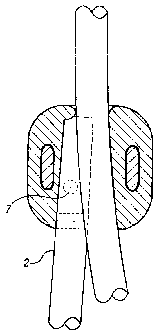
The present invention, as shown in Figure 1, comprises a catch mechanism in
which the length of a cord 2 can be held fast and adjusted (cord 2a) to fit
the use of
without any loose ends. The catch mechanism, as shown in Figure 1(a), shows
the
interference fit of the anchored cord 2 and the sliding cord 2a due to the
longitudinal taper
2 0 of the cord cavity. This also shows the location of the anchor pin 7 in
relation to the
anchored cord 2.
The catch mechanism, as shown in Figure 2, comprises a top portion 3 and a
bottom portion 4. The top portion 3 has an outside prong 5(a) with a
triangular cross-
2 5 section centre that grips and centres the cord 2, preventing the cord 2
from slipping and a
hold down prong 6 that forces the cord 2 into the base of the anchor pin 7 to
a maximum
pressure without impeding the assembly of the top portion 3 and the bottom
portion 4.
The anchor pin 7 arises from the bottom portion 4 rnid-way between the outside
prong
5(a) and the hold down prong 6. The bottom portion also has an outside prong
5(b) with a
3 0 triangular cross-section centre that grips and centres the cord 2
preventing the cord 2 from
slipping. Figure 2 also shows the side view of the compression ledge 8(b) on
the top
portion 3 and the compression ledge 8(b) on the bottom portion 4 that are both
adjacent to
CA 02483521 2004-11-O1
the anchor pin 7.
Figure 3 shows the tapered raised compression ledge 8(b) of the top portion
inside the
outside prongs 5(a), that forces the cord 2 into the anchor pin and allows for
the
interference fit of the top portion and bottom portion of the catch mechanism
after
assembly. The radiused inlets/outlets 16, which guide and protect the sliding
cord 2 from
wear are shown. The end assembly I I encloses the end of the anchored cord 2.
The top
sliding cavity 10(a) holds the sliding cord 2a. The walls of the elongated
keyway pin 9(a)
and keyway pin 9(b) are parallel to each other and are rounded at the ends to
ease
2 0 insertion into the keyway cavities of the bottom portion of the catch
mechanism. The
keyway pins 9(a) and 9(b) are slightly less in length that the depth of the
keyway cavities
on the bottom portion of the catch mechanism to allow for compression of air
during
assembly. The outside prong 5(a) is 90 degrees to the elongated keyway pins
9(a) and 9(b)
on the anterior end of the compression ledge 8(b) of the top portion. The hold
down prong
6 is also perpendicular to the elongated keyway pins 9(a) and 9(b) on the
posterior end of
the compression ledge 8(b). The compression ledge 8(b) acts to compress the
anchored
cord 2 by forcing an increase in width which increases the compression by
forcing the
anchored cord into the sliding cord 2a, The end of the cord 2 is compressed
further by the
lengthwise taper of the sliding cord cavity I5, which therefore interferes
with the sliding
2 0 cord 2a, increasing the tension of the slide, as also indicated in the
cross-hatched portion
of Figure lA. The end stop 11 positions the cord 2 for assembly of the catch
mechanism
and encloses and encapsulates an end of the anchored cord 2. Figure 3(a) shows
the
longitudinal taper in the cord enclosures.
2 5 Figure 4 shows the end elevated view of the top portion 3 of the catch
mechanism.
'fhe raised section 12 is inserted into the lower section 4, filling the cord
cavity upon
assembly. The top portion of the sliding cavity 10(a) is shown as well as the
radiused ends
of the keyway pins 9(a) and 9(b). The position of the upper compression ledge
8(b) is
shown in relation to the sliding cavity IO(a). The relationship of the size
and the location
3 0 of the anchor hold down pin 6 to the front prong 5(a) which centers the
anchored cord 2 as
it leaves the mechanism axe shown in this view.
.,.. w. ..._...,_ _w~._. ~ ~m.~~,~u ~~:~~:.~ ,,~.,~"~ ~~..~.~ .
~..~__..~_.~..~~.,. .~..~...._~_._..__ __ _. ___.._ _....w.....
CA 02483521 2004-11-O1
6
The end view of the top and bottom portions of the catch mechanism prior to
assembly is shown in Figure 5. The anchored cord 2 and the sliding cord 2a are
shown in
place for assembly into the extended cord cavity 17. The relative location of
the anchor
pin is shown prior to piercing the anchored cord 2. The cords will be
compressed into the
vertical tapered cord cavity 17 and the longitudinal taper 15 as shown in
Figure 1 A. The
compression ledges 8(a) and 8(b) also act to compact the cord 2 furthering the
compression. Figure 5 also shows the keyway cavities 13(a) and 13 (b) and the
tapered
walls 14 which when assembled with the top portion of the catch mechanism
force the
cord 2 into the taper bringing the meeting edges of the cords tighter together
and further
compressing and determining the pull-ability of the sliding cord 2a.
The end view of the assembled catch mechanism is shown in Figure 6 The
anchored cord 2 and the sliding cord 2a are shown in place within the
mechanism
The hidden lines on the anchored cord 2 show the amount of compression and the
penetration of the front prongs 5(a) and 5 (b) and the compression ledges 8(a)
and 8(b).
Figure d(a) shows the resulting compacting of the anchored cord 2 by the
compression created by three methods, the longitudinal taper, the vertical
taper 14 and
the compression ledges 8(a) and 8(b). They alter the shape of the anchored
cord and
2 o force tension on the sliding cord.
The bottom view of the bottom portion of the catch mechanism, as shown in
Figure 7, demonstrates the shape and position of the elongated keyway cavities
13(a) and
13 (b), the anchor pin 7, the outside prong 5(b), the sliding cord cavity
10(b), the end stop
2 5 11 and the compression ledge 8(a) of the bottom portion. ~ne or more
anchor pins 7
provide a breakaway mechanism. Anchor pin 7 can be elongated on the sides
toward the
cord pull. The degree of breaking strength of the mechanism is determined by
the length,
the width, the material of, the number of, the height of the parallel sides
of, and the extent
of the elongation of the anchor pins. Anchor pin 7 has straight, parallel
sides with a
3 0 tapered end which may allow penetration into the cord. The exterior wall
of the sliding
cord cavity and the exterior wall of the anchor cord cavity are not parallel
This creates a
longitudinal taper compressing the cords together as shown in Figure 1(a) The
radius cut
CA 02483521 2004-11-O1
7
16 on the inlet and outlet of the bottom portion eliminates chafing of the
cord, allows the
cord to smoothly be pulled at an angle to the outlet and allows the cord to
pull without
binding. The keyway cavities 13(a) and 13 (b) on the bottom portion are each
slightly
smaller than the inserting keyway pins 9(a} and 9(b) on the top portion of the
catch
mechanism This creates an interference fit that allows assembly and affixing
of the top
portion 3 and bottom portion 4 The walls of keyway cavities 13(a) and 13(b)
are parallel
to each other to create holding power and are of sufficient thickness to
prevent distortion
or to lose the interference fit. The depth of the keyway cavities 13(a) and 13
(b) are also
deeper than the length of the keyway pins 9(a) and 9(b) to allow for total
closure of the
catch mechanism.
Operation:
The operation of the slip grip device can best be understood by reviewing the
various
functions which the slip grip device performs.
Engaging and holding anchor cord
This is accomplished within the slip grip components thraugh use of
2 0 compression plates 8(a) and 8{b), prongs 5(a) and 5(b), prong 6 and anchor
pin 7.
The anchor cord is compacted by the application of the compressing plates
narrowing the anchor cord chamber. Prongs 5(a) and 5(b) further compress the
cord at localized points. Prong 6 provides further localized compression of
the
cord by forcing the cord toward the base end of the anchor pin. The anchor pin
2 5 engages the cord by indenting and compressing into the surface of the
anchor
cord. If the anchor pin is small in diameter and the cord is permeable, the
pin
may penetrate the cord. Penetratian is not necessary but can occur in certain
materials. Alternatively, as the anchor pin is elongated and enlarged to
increase
or decrease the breakaway, the pin may just engage the cord, exerting pressure
3 0 without penetration (piercing).
CA 02483521 2004-11-O1
Operation of sliding cord for purposes of adjustment
Friction is provided by frictional contact of the two cords anchor cord 2
and sliding cord 2a and the cavity containing them. Rather than a single point
or
several isolated points of contact, there is full length interior contact,
which
generates greater friction. The greater the amount of frictional contact the
smoother the sliding action as greater surface area contact diminishes the
effect
of variations of the cord surface. The cords are positioned side by side with
full
contact the entire length of the cavity of the slip grip device. There are a
number
of factors which contribute to full length contact being maintained. Friction
is
2 0 applied through use of two dimensional tapering, both longitudinally and
vertically (transversely). Longitudinal taper 15 runs within the entire length
of
the cavity. The amount of friction changes with the variation of the width at
the
wide part and the width at the narrow part of the taper. The width of the
longitudinal taper cavity affects the preload of the two cords: the tighter
the fit of
the preloaded cords, the greater the friction. Altering the degree of taper
further
effects the amount of friction applied to the sliding cord as it determines
the
interference fit of the two cords. The degree of vertical taper affects the
friction.
As the cords are forced together by the compression plates into the bottom of
the
narrowing cavity, the sliding cord and the anchor cords are forced together
2 0 creating friction along the contact of the anchor cord and the sliding
cord. As the
bottom of the cavity narrows, the sliding cord and the anchor cords are forced
tighter together. By changing the included angle of the vertical taper, the
frictional pressure on the sliding cord can be altered. The closer the end of
the
anchor cord is to the anchor pin 7, the less friction is applied to the
sliding cord
2 5 as there is less lineal contact against the sliding cord. As the end of
the anchor
cord moves toward the cap end increasing the distance between the anchor pin
and end of the anchor cord, friction against the sliding cord increases as
more
contact area and greater interference are provided. The amount of compression
on the anchor cord is one of the factors that determines the pressure on the
3 0 sliding cord. As the cords are compressed between the compression plates
on the
top and bottom of the anchor cord cavity and against the outside angled
vertical
. _.... _..~«" ~,~~~,,.,~.~~,~~,~~~,,~~,~"M~~,~,.~~,~..._.~.."~,~~__
__~_.__.~...~.._._,.... ...__._ _..._.m".~.......,...~..,..~.~..~.~..___.._,
_..__~_..___..
CA 02483521 2004-11-O1
9
side wall of the anchor cord cavity, the compression forces the sliding cord
contact side of the anchor cord and the contact side of the sliding cord
together.
This allows the anchor cord to exert greater pressure against the sliding
cord, as
this is the only direction the anchor cord can move as it is contained within
the
cavity on the other three sides. This results in the sliding cord transmitting
outward pressure against the containment walls of the sliding cord cavity as
well
as the anchor cord. The closer the sliding cord cavity is to the size of the
cord,
the greater the friction effect upon the sliding cord. A tighter fitting
sliding cord
cavity increases the amount of friction against the sliding cord. Similarly,
the
closer the anchor cord cavity is to the size of the anchor cord, the greater
the
friction effect upon the sliding cord. A tighter fitting anchor cord cavity
increases
the amount of friction against the sliding cord. It is preferred that sliding
cord
cavity be the same shape as the cross-sectional shape of the sliding cord to
allow
greater contact and to maintain the initial cross-sectional shape of the
sliding
cord. Similarly, the closer the anchor cord cavity is to the shape of the
anchor
cord, the greater the applied frictional pressure upon the sliding cord.
Localized
pressure paints created by prongs 5(a) and 5(b) provide additional holding
compression on the anchor cord. This additional holding compression expands
the localized points into the sliding cord by forcing the compressed points of
2 0 contact toward the sliding cord increasing the friction at these points.
Prong 6,
like prongs 5(a) & 5(b), provides further compression of the anchor cord into
the
sliding cord. As the compression increases the cord spreads into the sliding
cord
at that point of contact. When the inside edge of the end cap and the exterior
anchor wall cavity are radiussed, it acts as an incline plane and further
directs the
2 5 end of the anchor cord into the sliding cord. Forcing the cord against the
end cap,
upon assembly, allows for more frictional pressure against the sliding cord,
through the mushrooming effect the preloading lateral force creates on the
anchor cord.
3 0 With many types of cord, the tension tends to improve over time, by
becoming tighter and smoother. A contact friction point is very wide (length
of
....._. ... ~~~.~ r~.3~~~ ~,. . ~,~:~~~- ._.~.,ww.. . .. _._.~.._. __~
~..~_____ _____. _____.
CA 02483521 2004-11-O1
the slip grip) the sliding cord and the anchor cord, over time, mate or lap
together
for smoother movement. Noticeable impact of variations in cord diameter is
lessened, because of the wide contact area of the anchor cord and the sliding
cord, allowing the sliding cord to move against the anchored cord with more
5 consistent action. Like the softening effect of long-term use on a pair of
stiff new
blue jeans, cord softens and fluffs and expands to accommodate itself around
the
adjoining cord and into the containment cavity. When the cord is new it is
condensed and through use the fibres become less tightly wound and action
becomes silky smooth. . (Note that this point mainly applies to certain cords,
for
10 example cotton materaads)
By creating a sliding cord cavity of the same shape and size as the cord,
the cavity partially contains and accommodates the cord. Force exerted on the
compressed anchored cord will be transmitted through the sliding cord forcing
pressure toward the opposite wall of the sliding cavity, echoing the pressure
back
toward the centre; thus the cord is compressed into the shape of the sliding
cord
cavity maintaining the original cord shape. Rather than losing pressure at a
single contact point, force is exerted around the cord back into the middle,
so it
comes out radially; thus maintaining the original shape of the cord. The
sliding
2 0 cord will maintain its original shape if the sliding cord cavity is made
to fit the
cord size and shape. Therefore, the action remains consistent. Friction
between
anchor cord and sliding cord increases as the anchor cord is forced against
the
sliding cord at contact area. 13y increasing the amount of cord contact,
greater
friction can be achieved , as shown in FIG. lA. Complimentary cavity/cord
2 5 shape keeps cord in original cross-section shape. The smaller the
tolerance of
cord to the sliding cord cavity, the greater the influence of friction from
anchor
cord to sliding cord. This applies equally to for anchor cord. Compression of
anchor cord between compression plates and the anchor cord side cavity force
expansion of the anchor cord to only go towards sliding cord creating
friction.
Operation of breakaway mechanism.
CA 02483521 2004-11-O1
11
Lateral movement of the anchor cord within the slip grip cavity initiates
the breakaway mechanism. As lateral movement of the anchor cord increases,
the lateral pull overcomes the compression force of the plates, the
compression
points of prongs 5(a), 5(b) and 6 and the compression indent force of the
anchor
pin. As the cord moves along the inclined planes of 5(a) and 5 b, the inclined
plane of the top of the anchor pin and the inclined plane of prong 6, outward
pressure is applied into parts 3 and 4 (the top and bottom of the slip grip
assembly) exerting pressure on the keyway pins 9(a) and 9(b) and keyway
cavities 13(a) and 13(b). When the pressure becomes great enough, it overcomes
the interference fit and Iifts the top, releasing the cord. The degree of
interference between keyway cavity and keyway pins determines the amount of
outward pressure required to initiate breakaway.
Breakaway is partially created by the anchor pin shape and size
combined with the interference fit on the two pins and cavities which hold the
top and bottom portion of the clasp together. If the anchor pin is narrow
compared to its height (higher than it is wide), when the anchor cord is
pulled, the pin can bend to give the breakaway. When the cross-section of the
anchor pin is elongated, at a point where the elongation is greater than the
height
2 0 of the pin, the pin may no longer bend or break at that point. As the
anchor card
is pulled, the cord will ride up along the top of the anchor pin and the
interference fit of the top to the bottom will partially release allowing the
cord to
slip over the top of the anchor pin and break away. A predetermined breakaway
point is created through altering the size of the anchor pin, the amount of
2 5 interference in combination with the front prongs 5(a) and 5(b) and prong
6 and
the compression of the cord. The breakaway point can be set to a predetermined
pressure point variable (based on size and material) potentially anywhere from
ounces to tons. This allows a safety factor to be set for the slip grip.
Degree of
interference on keyway pins 9(a) and 9(b) and keyway cavities I3(a) and 13(b)
3 0 determines the breakaway point. Breakaway occurs when top (3) and bottom
(4)
separate and the anchor cord is released. When the anchor cord moves along the
CA 02483521 2004-11-O1
12
inclined planes of 5(a), S(b), 6 and top of anchor pin, the increased outward
pressure separates the top (3) and bottom (4) as the pressure overcomes the
interference fit of the pin and the cavity. Outward pressure on top and bottom
breaks contact of interference/pin/cavity 9(a) and 9(b) and 13 (a) and 13(b)
separates the top and bottom of the slip grip allowing for release of the
anchor
cord. The breakaway pressure point is partially determined by the size and
shape
and material of the cord and the slip grip. Prongs 5(a) and 5(b) and 6 all
taper to
allow easier and controllable lateral movement. The steeper the incline angle
of
the prongs 5(a) and 5(b) and prong 6 and top of anchor pin, the greater the
force
required to separate the top (3) and the bottom (4) and achieve breakaway. As
enough pressure is applied to cause the anchor cord to begin to move, the
anchor
cord is forced to follow the inclined planes of 5(a), 5(b) and the top of the
anchor
pin. When the applied pressure pulling the anchor cord and moving up the
incline plane is great enough, the top (3) and bottom (4) will separate
releasing
the anchor cord. When the pull on the anchor cord outweighs compression
pressure from plates, 5(a), 5(b) and 6 and anchor pin, the lateral movement
creates outward pressure as the cord rises up the inclined planes. Release of
the
top and bottom pin/ cavity is dependant upon the degree of interference. A pre-
determined release pressure point can be achieved by adjusting the degree of
2 0 interference between pin and cavity. Movement of the anchor cord is
affected by
the degree of angle of the inclined plane of 5(a), 5(b) and 6. The steeper the
angle of the inclined plane, the greater is the pressure exerted on the anchor
cord
required to separate the top and bottom and release the anchor cord.
2 5 The designed slip grip mechanism is more durable, more consistent, more
easily
adjusted and safer than any other type of catch now available. The present
invention,
unlike the prior art, is specifically designed to have only two pieces with no
moving parts,
be easily assembled and have a built in tension mechanism that is capable of
being used
effectively on cord of varied size and type. The present invention can be used
as an
3 0 attractive, cost-effective, efficient anchoring device for cord necklaces.
As the invention
could be developed into any size, it could be used for cords on glasses or for
hanging
CA 02483521 2004-11-O1
13
pictures. It could be used to attach a watch, key chain or as a bag fastener.
It could be
used to close sports bags, purses, or sports equipment. It could be used to
attach gear to
roof racks. It could be used to organise office supplies or kitchen utensils.
It could be
used to hang toys for small children as it has the breakaway function. It
could be used to
keep any equipment in place: tarps, wall paper, sleeping bags and the like. It
could be
used by people impaired by arthritis, as it does not require difficult tying
or fastening. It
could be used for camping equipment or for hobby equipment. It could be used
in the
medical world for such things as IV's and adjustable slings. There are
countless industrial
applications. Anywhere that adjustability of a gripping cord is required could
use this
invention. And it can be reused and reset countless times.
This present invention has only two parts, greatly simplifying assembly and
increasing cost-effectiveness. It can be made in any size and will accommodate
varied
types of cord material. The exterior can be made in varied colours and shapes.
It could
even be imprinted with a company logo. The invention is durable safe and
clean.
In this patent document, the word "comprising" is used in its non-limiting
sense to
mean that items following the word are included, but items not specifically
mentioned are not
2 0 excluded. A reference to an element by the indefinite article "a" does not
exclude the
possibility that more than one of the element is present, unless the context
clearly requires that
there be one and only one of the elements.
It will be apparent to one skilled in the art that modifications may be made
to the
2 5 illustrated embodiment without departing from the spirit and scope of the
invention as
hereinafter defined in the Claims.