Note : Les descriptions sont présentées dans la langue officielle dans laquelle elles ont été soumises.
CA 02483955 2010-07-14
VALVE SYSTEM FOR THE COUNT ROLL OF AN INTERFOLDING MACHINE
FIELD OF THE INVENTION
[00021 This invention generally relates to an interfolding machine for folding
sheets of
material, and more specifically, to an interfolding machine that includes a
count roll to form
a separation in a stack of interfolded sheets at a predetermined sheet.
BACKGROUND OF THE INVENTION
[00031 Interfolding of a web or sheet material (e.g., napkins, paper towels,
tissue, etc.)
is frequently performed using folding rolls of a folding machine. The folding
rolls are
operable to fold a series of successive sheets that are cut from one or more
webs and
supplied to the folding rolls in an overlapping relationship. Upstream of the
folding rolls, the
sheets are cut against a bed roll by a knife roll, and the sheets are then
supplied to a retard
roll that functions to provide the desired overlapping relationship of the
sheets. From the
retard roll, the sheets are advanced by a lap roll and are then supplied to
the folding rolls for
interfolding, to create a stack of interfolded sheets at the discharge of the
folding rolls. A
1
CA 02483955 2004-10-04
count roll is located adjacent the lap roll, and rotates in a timed
relationship with the lap roll.
The count roll is selectively operable to eliminate the sheet overlap at a
desired sheet count,
in order to create a separation in the supply of overlapped sheets to the
folding rolls. The
separation in the supply of sheets to the folding rolls functions to separate
the stack of sheets
discharged from the folding rolls into adjacent stacks or logs of sheets, each
of which has a
desired sheet count. The sheet overlap is interrupted by means of a vacuum
system in the
count roll that folds the leading edge of one of the sheets onto itself at the
desired count. As
the count roll rotates, the vacuum system is selectively actuated to engage
the leading edge
of the sheet as the sheets is transported on the lap roll, and carries and/or
retains the leading
edge of the sheet while the remainder of the sheet is advanced by the lap
roll. The count roll
then releases the leading edge of the sheet, and the retention of the
remainder of the sheet on
the count roll creates the sheet fold that eliminates the overlap between the
leading edge of
the sheet and the trailing edge of the downstream sheet.
[00041 However, known count roll systems for interfolding machines have
drawbacks
and limitations. For example, the operational speed of the interfolding
machine is limited by
a relatively short switching time that is available for actuating the vacuum
system to turn the
count roll valves on and off. Further, known count rolls use two vacuum ports
on the count
roll that are 180 apart, which can only provide an even count of sheets.
2
CA 02483955 2004-10-04
SUMMARY OF THE INVENTION
[00051 In accordance with the present invention, there is provided a count
assembly
that provides the ability to form a separation of successive sheets of
material through an
interfolding machine at a desired sheet count. The count assembly includes a
count roll that
is selectively supplied with vacuum from a vacuum assembly, which includes a
manifold
having a plurality of manifold ports coupled to a valve body having a
plurality of interior
chambers. A spool is located within a cavity defined by the valve body. The
spool includes
a plurality of spool ports to provide a plurality of respective vacuum paths
to a rotating count
roll. The spool also includes a plurality of machined openings along a
perimeter or outer
surface, and each machined opening in the spool communicates a respective
manifold port
with a respective interior chamber disposed in the valve body.
[00061 The invention also provides an interfolding machine for interfolding
sheets of
material, which are separated at a predetermined count of sheets. The
interfolding machine
includes a roll configured to count successive sheets of the material through
the interfolding
machine. The roll generally includes a series of holes or ports configured to
communicate
vacuum to the surface of the roll at a predetermined sheet count and at a
desired point in
rotation of the roll. The interfolding machine further includes a vacuum
assembly that
selectively communicates vacuum pressure to the holes or ports of the roll.
The vacuum
3
CA 02483955 2004-10-04
assembly includes a manifold having a series of manifold ports, and a valve
body having a
series of chambers, each of which is in communication with one of the series
of manifold
ports. The vacuum assembly further includes a spool inserted in the valve
body. The spool
is connected to the roll so as to rotate with the roll, and includes a
plurality of spool ports
along a circumference thereof to provide respective paths to communicate the
vacuum
pressure to the holes or ports of the folding roll. Each opening in the spool
communicates
one of the manifold openings with one of the chambers of the valve body. The
vacuum
assembly further includes a control valve for selectively exposing at least
one of the valve
chambers to atmosphere such that the roll selectively releases the web
material at a
predetermined point in rotation of the roll.
[00071 The invention also provides a method of separating successive sheets of
overlapped sheets of material at a desired sheet count. The method generally
includes the
acts of providing a control valve, a spool, and a count roll, the count roll
configured to create
a fold separating the successive sheets of web material at a desired sheet
count. The spool
includes a plurality of chambers, each of which is configured to communicate a
vacuum
pressure at a plurality of ports along a perimeter of the spool with a
plurality of holes in an
outer surface of the count roll. The method further includes the acts of
rotating the spool
with respect to the control valve; aligning one or more of the chambers in the
spool with an
opening in the control valve; communicating one or more of the aligned
chambers with
4
CA 02483955 2004-10-04
atmosphere via the opening in the control valve; and releasing the vacuum
pressure in one or
more of the aligned chambers to atmosphere.
[0008] Other objects, features, and advantages of the invention will become
apparent
to those skilled in the art from the following detailed description and
accompanying
drawings. It should be understood, however, that the detailed description and
specific
examples, while indicating preferred embodiments of the present invention, are
given by way
of illustration and not of limitation. Many changes and modifications may be
made within
the scope of the present invention without departing from the spirit thereof,
and the invention
includes all such modifications.
BRIEF DESCRIPTION OF THE DRAWINGS
[009] Preferred exemplary embodiments of the invention are illustrated in the
accompanying drawings in which like reference numerals represent like parts
throughout. In
the drawings:
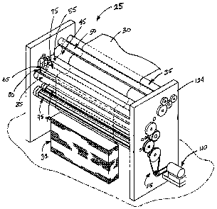
[0010] FIG. 1 is an isometric view of an interfolding machine employing a
count roll
valve system in accordance with the present invention.
[0011] FIG. 2 is a schematic side elevation view of the interfolding machine
as shown
in FIG. 1.
CA 02483955 2004-10-04
[0012] FIG. 3 is a detailed isometric view of a count roll valve assembly
incorporated
in the interfolding machine of FIGS. 1 and 2.
[0013] FIG. 4 is a first detailed cross-sectional view of the count roll valve
assembly
along line 4-4 of FIG. 3.
[0014] FIG. 5 is a second detailed cross-sectional view of the count roll
valve
assembly along line 5-5 of FIG. 3.
[0015] FIG. 6 is a cross-sectional view of the count roll valve assembly along
line 6-6
of FIG. 4.
[0016] FIG. 7 is an exploded isometric view of the count roll valve assembly
shown in
FIG. 3.
[0017] FIG. 8 is a schematic diagram of showing the count roll assembly of
Figs. 3-7
engaging a leading edge of a sheet of material from a lap roll assembly, at a
desired sheet
count.
[00181 FIG. 9 is a schematic diagram similar to FIG. 8 completing a fold in of
the
sheet of material to form a separation in the sheets supplied to the folding
rolls.
6
CA 02483955 2009-11-18
DETAILED DESCRIPTION OF THE PREFERRED EMBODIMENTS
1. Folding Machine
[00191 Referring to FIGS. 1 and 2, an interfolding machine 25 is operable to
convert a
web of material 30 into a stack of interfolded sheets of material shown at 32.
Interfolding
machine 25 incorporates a count roll valve system in accordance with the
present invention,
and generally includes a first pull roll 35 and a second pull roll 40 that
receive the web of
material 30 along a path (illustrated by an arrow 42 in FIG. 2) from a supply
roll (not shown)
into the interfolding machine 20. The first and second pull rolls 35 and 40
define a nip
through which the web of material 30 passes, and function to unwind the web of
material 30
and feed the web of material 30 in a path (illustrated by an arrow 44 in FIG.
2) toward a nip
defined between second pull roll 40 and a bed roll 45. The web of material 30
is then
advanced by bed roll 45 toward a knife roll 50. In a manner as is known, the
knife roll 50
cuts the web of material 30 into sheets, each of which has a predetermined
length, and the
bed roll 45 carries the sheets of material along a path (illustrated by arrow
52 in FIG. 2)
toward and through a nip defined between bed roll 45 and a retard roll 55,
which rotates at a
slower speed of rotation than the bed roll 45. In a manner as explained in
U.S. Patent No.
7,407,161, the retard roll 55 cooperates with a nip roller assembly 60 (FIG.
2) to form an
overlap between
7
CA 02483955 2004-10-04
the consecutive sheets of material. The retard roll 55 carries the overlapped
sheets of
material along a path (illustrated by arrow 68 in FIG. 2) to a lap roll 65.
[0020] The lap roll 65 works in combination with the count roll 20 to
eliminate the
overlap between adjacent sheets of material at a predetermined sheet count, so
as to create a
separation in the stack 32 of interfolded sheets discharged from the
interfolding machine 25.
The lap roll 65 carries the overlapped sheets 30 along a path (illustrated by
arrow 78 in FIG.
2) toward a nip defined between a first assist roll 80 and an adjacent second
assist roll 85.
The first and second assist rolls 80 and 85 feed the sheets of the material to
a nip defined
between a first folding roll 90 and a second folding roll 95.
[0021] Referring to FIG. 2, the first and second folding rolls 90 and 95
generally
rotate in opposite directions (illustrated by arrows 96 and 98, respectively,
in FIG. 2) to
receive the overlapped sheets of material 30 therebetween. The periphery of
the first folding
roll 90 generally includes a series of the tucker assemblies 105 and gripper
assemblies 100
uniformly and alternately spaced to interact with a series of tucker
assemblies 105 and
gripper assemblies 100 of the adjacent second folding roll 95. The series of
alternately
spaced tucker assemblies 105 and gripper assemblies 100 of the first and
second folding rolls
90 and 95 interact to grip, carry, and release the sheets of material in a
desired manner so as
to form stack 32 of interfolded sheets. The folding rolls 90 and 95 may be
driven by a drive
system 110 having a drive belt assembly 115 (FIG. 1).
8
CA 02483955 2009-11-18
100221 The stack 32 of interfolded sheets is discharged from between the first
and
second folding rolls 90 and 95 in a generally vertically-aligned fashion. The
stack 32 of
interfolded sheets may be supplied to a discharge and transfer system (not
shown), which
guides and conveys the stack 32 from the generally vertically-aligned
orientation at the
discharge of the interfolding machine 25 to a generally horizontally-aligned
movement. One
embodiment of a suitable discharge and transfer system is described in U.S.
Patent No.
6,712,746 entitled "Discharge and Transfer System for Interfolded Sheets,"
filed May 5,
2000. Another representative discharge and transfer system is illustrated in
U.S. Patent No.
6,865,861.
2. Count Roll Assembly
[00231 FIGS. 3-7 show a count roll valve assembly 130 of the present
invention,
which is mounted to each end of count roll 20. Count roll 20 is rotatably
mounted to the
frame of interfolding machine 25 by a pair of bearing box assemblies 132. Each
count roll
valve assembly 130 generally includes a pair of ball bearings 135, a rotating
spool 140, a
valve body 145, a pair of wear plates 150, an OFF valve 155, and a manifold
cover 160.
[00241 The rotating spool 140 of the count valve assembly 130 slips over a
roll journal
170, such that roll journal 170 is received within an internal passage 142
defined by spool
9
CA 02483955 2004-10-04
140. Each roll journal 170 includes a flange 176 that is directly connected
one of the ends of
count roll 20, in a manner as is known. Flange 176 defines port paths 185 that
are aligned
and communicate with port paths 185 that open onto the ends of count roll 20.
Port paths
185 of flange 176 communicate with separate interior chambers or passages 200a-
d formed
in the body of spool 140.
[0025) The rotating spool 140 also includes radially and axially spaced
machined
openings or ports 21 Oa-d that open onto the outer surface 212 of the body of
spool 140.
Each opening 21 Oa-d communicates with one of the separate interior chamber
200a - d
disposed in the spool 140, establishing communication with the outer surface
of spool 140.
Each chamber 200a- 200d connects one of the distinct openings 21 Oa-d to one
of the
respective port paths 185a-d and to the respective holes 218a-d along the
outer surface of the
count roll 20.
[00261 The valve body 145 does not rotate, and is supported on spool 140 by
bearings
135, which are affixed to the ends of spool 140 and within inwardly facing
recesses formed
in the ends of valve body 145. Wear plates 150 straddle the outer one of
bearings 135 at the
bearing box 132/ frame side 222 (See FIG. 1) of the assembly 20. Valve body
145 is a
generally cylindrical member, and includes a series of circumferential
recesses 148a, 148b,
148c and 148d that extend inwardly from its outer surface. Valve body 145
defines an
interior 149 within which spool 140 is received, and recesses 148a-148d
communicate with
valve body interior 149 through respective passages 151 a-151 d (FIGS. 4,5).
CA 02483955 2004-10-04
[0027] Manifold 160 generally includes a series of four C-shaped cover
components
160a-d interconnected with a series of four C-shaped vacuum inlet components
165a-d. The
width of each of the cover components 160a-d and respective vacuum inlet
components
165a-d can vary. The preferred cover components 160a-d each extends a first
portion of the
circumference of the manifold 160, and each of the vacuum inlet components
165a-d extends
the remaining circumference of the manifold 160. The manifold 160 further
includes a series
of gaskets 230 disposed between adjacent cover components 160a-d and vacuum
inlet
components 165a-d. Respective cover components 160a-160d and respective vacuum
inlet
components 165a-165d are secured together to enclose respective valve body
recesses 148a-
148d. With this construction, manifold 160 defines a series of annular vacuum
supply
cavities, each of which is supplied with vacuum from a vacuum source connected
to vacuum
inlet components 165a-165d, and which communicate with valve body interior
through
passages 151 a-151 d. Of course, the specific construction of manifold 160 may
vary form
that which is shown and described, which is not limiting on the invention.
[0028] The OFF valve 155 is generally a port cover plate structure that
overlies the end of
the spool 140 opposite plate portion 144. OFF valve 155 is spring-loaded,
stationary and presses
against the outer wear plate 150. In the illustrated embodiment, OFF valve 155
generally includes a
U-shaped opening 225 through which roll journal 170 extends. Opening 225 in
OFF valve 155
selectively communicates chambers or passages 200a-d with atmosphere during
rotation of count
valve 20 and spool 140. When the energized or activated port passes the U-
shaped cutout in valve
11
CA 02483955 2004-10-04
155, the respective port is exposed to the atmosphere, which functions to cut
off the supply of
vacuum pressure to the holes 218a-d of the count roll 20. This release of
vacuum pressure functions
to release engagement of the sheet 30 with the outer surface of count roll 20.
[00291 In operation, when a desired sheet count is attained, the vacuum source
is
actuated to supply vacuum pressure to a selected one of vacuum inlet
components 165a -
165d, such as 165a. Vacuum pressure is transferred through one of the recesses
in valve
body 145, such as recess 148a, and through the recess opening such as 151 a to
the chamber
or passage, such as 200a, in spool 140. In this manner, vacuum is supplied to
the appropriate
port path 185 and the associated set of vacuum ports, such as 218a, that open
onto the
surface of count roll 20. In this manner, the supply of vacuum to the vacuum
ports such as
218a functions to engage the leading edge of a sheet 30 out of overlapping
relationship with
the trailing edge of the downstream sheet, as shown in FIG. 8. Continued
rotation of count
roll 20 folds the sheet 30 onto itself, to create a separation in the supply
of sheets to the
folding rolls. When count roll 20 attains a rotational position corresponding
to the location
at which sheet 30 is to be released, spool 140 is positioned so that the
activated chamber or
passage, such as 200a, enters opening 225 in OFF valve 155. As noted
previously, this
release of vacuum pressure releases engagement of the sheet 30 with the outer
surface of
count roll 20, so that the folded sheet 30 is release and continues in the
path toward folding
rolls 90, 95, as shown in FIG. 9.
12
CA 02483955 2004-10-04
[0030] The location at which activation or ON vacuum is supplied can be
adjusted as
desired by rotating the stationary valve body 145. Similarly, the location at
which vacuum is
cut off can be adjusted by rotation of OFF valve 155. Passages 151 a- 151d are
in axial
alignment with each other, which ensures that vacuum actuation occurs at a
consistent point
in the rotation of spool 140, regardless of which of vacuum inlets 165a-165 is
actuated.
[00311 The present invention provides numerous advantages in operation,
including
the ability to closely control the location at which vacuum is supplied to and
cut off from the
vacuum ports of the count roll. In addition, the chambered design of the
present invention
increases the available valve switching time. In contrast to known valve
assemblies, each
chamber 200a-d has an available dead time in excess of two hundred-seventy
degrees of
rotation, during which the chamber can be energized or activated with vacuum
pressure.
This increase in the available switching time can increase the potential
operating speed of the
interfolding machinery. Furthermore, individual port activation provides the
availability of
any sheet count, including odd numbered counts. In contrast, known valve
assemblies are
only able to provide even numbered counts.
[0032] A wide variety of machines or systems could be constructed in
accordance
with the invention defined by the claims. Hence, although the exemplary
embodiment of a
count assembly 20 in accordance with the invention will be generally described
with
reference to an interfolding machine for counting overlapped sheets of
material 30 to be
interfolded into a stack 32, the application of the count assembly 20 is not
so limited. The
13
CA 02483955 2004-10-04
count assembly 20 of the invention could be employed to count a variety of web-
materials
being fed for a wide variety of uses and is not limiting on the invention.
[00331 The above discussion, examples, and embodiments illustrate our current
understanding of the invention. However, since many variations of the
invention can be
made without departing from the spirit and scope of the invention, the
invention resides
wholly in the claims hereafter appended.
14