Note : Les descriptions sont présentées dans la langue officielle dans laquelle elles ont été soumises.
CA 02484132 2009-09-04
ELECTRICAL BOX ZXMSIONT
BACKGROUND
This invention generally relates to electrical equipment
for housing electrical devices such as switches and
outlets, and particularly to electrical box extensions-
Electrical boxes are commonly used to provide electrical
service at convenient locations within buildings. The
electrical boxes are commonly formed of plastic or metal
and are usually securely fastened by screws or nails to the
framework of a structure being prepared for
electrification. In newly constructed buildings, the open
face of the electrical box, within which an electrical
device such as an outlet or switch will be mounted, is
usually flush with the surface of the wall or ceiling in
which it is installed.
When buildings are renovated or restored or otherwise
modified from their original wall and ceiling surfaces, it
is common for renovators to lay down new sheet stock such
as sheet rock, paneling, and the like, over the existing
ceilings or walls, This process of layering causes the
existing electrical boxes to become recessed within the
built-up wall by the thickness of the new sheet stock. A
need for extension therefore occurs when the box or mud
I
CA 02484132 2009-09-04
ring has been placed and then tile, brick or some other
wall covering is added thereby causing the screw mounts for
plugs and/or switches to be recessed within the wall.
To solve this problem, box extenders of several different
types have been developed. One type relies on a friction
fit to hold the box extender in the existing electrical
box. This extender does not provide a secure attachment to
the existing box and may allow an attached electrical
device to slide further within the box as the extender will
slide based on an external force.
Another type of extender consists of an extension having
walls of approximately the same configuration as the
existing box and of fixed depths of extension. The extender
is available in several depths to accommodate several
different sheet stock thicknesses. Although there are
several depths available, they depth is not continuously
variable resulting in an inability to consistently provide
a depth extension bringing the existing box flush with the
outer wall surface.
Another type of extender includes a body portion having at
least one wall and open faces. The extender includes side
flanges having holes that align with brackets that are
connected to the electrical box. This extender is difficult
to use and install as brackets must be firmly attached to
the electrical box and then two screws are used to attach
each flange of the extender to the electrical box.
2
CA 02484132 2009-09-04
There remains a need to extend the electrical box with a
minimal number of parts that provide ready height
adjustment while maintaining mechanical and structural
soundness and electrical connectivity including ground, and
thereby compensate for add-ons to a wall that cause depth
to be added between the box or ring and the outer wall.
SU741RY
Disclosed is a mud ring or adapting member for an
electrical box that is adapted to receive an extending
member or slider and is adapted to receive one or more
elevating fasteners whereby turns of the one or more
elevating fasteners extend or retract the slider relative
to the adapting member. The mud ring may have detachable
brackets that may be used as a conventional means of
attaching switches or outlets and may be detached to allow
for the insertion and travel of the slider. Disclosed is an
electrical box extension including an extending member with
one or more fastening brackets, one or more fastening
brackets and one or more elevating fasteners such as a
double reverse screw or a standard threaded screw with
attached grommet for mechanically electrically connecting
the extending member and the box via the fasteners,
brackets, and/or ridges and thereby providing sufficient
mechanical resistance to support the adjustable elevation
3
CA 02484132 2009-09-04
of the extending member and providing a flush surface for
surface mounted sockets, switches and their associated
plates. The extending member, the mud ring, or both,
provide electrical connectivity via one or more protrusions
or projections from the slider against the adapting member
or via one or more protrusions or projections from the
adapting member against the slider, or a combination of
both means of mechanical and electrical connectivity.
The invention in its several embodiments includes a mud
ring for electrical box extension having an adapting plate
portion or member with a substantially centrally located
aperture and bordering the aperture is a flange portion
substantially perpendicular to the adapting plate member
and extending in the direction of the outward side of the
adapting plate portion and oriented substantially about a
principal axis of extension of the mud ring. In addition,
the mud ring further includes at least one adaptor fastener
mounting plate preferably extending from an edge of the
adapting plate member, each of the at least one adaptor
fastener mounting plates having an end section with an
aperture for receiving a fastener axially and laterally,
wherein each end section of the at least one adaptor
fastener mounting plate extending substantially in the
direction of inward side of and preferably below the flange
portion.
Accordingly, the mud ring is adapted to receive an
extending member, wherein each of the at least one adaptor
4
CA 02484132 2009-09-04
fastener mounting plate has an associated extender fastener
mounting plate, where each extender fastener mounting
plate has an aperture for receiving a fastener, each
extender fastener mounting plate fixedly attaches to the
extending member and each extender fastener mounting plate
aperture is preferably substantially aligned with the
associated adaptor fastener mounting plate aperture and
wherein the extending member includes a polyhedron-shaped
surface with substantially rectangular-shaped facets about
a principal axis of extension and in alternative
embodiments includes circular and oval shaped or otherwise
tubular surfaces.
The extending member is preferably oriented about the
principal axis extension of the mud ring with the outward
surface of the extending member in close proximity to the
inward-side of the flange portion, wherein the outer
surface of the extending member has at least one protrusion
in mechanical and electrical contact with the inward side
of the flange portion and at least one fastener for
detachably attaching the adapting plate portion to the
extending member by way of the aligned adapting member
fastener mounting plate aperture and the aligned extending
member fastener mounting plate.
Alternative embodiments include the inner side of the
flange having at least one protrusion in mechanical and
electrical contact with the outward side of the extending
member. By these embodiments, the at least one protrusion
5
CA 02484132 2009-09-04
maintains mechanical and electrical connectivity between
the extending member and the adapting member while the
adjusting of the at least one fastener modifies the height
of the extending member relative to the adapting member in
an adjustable and substantially reversible fashion. In
addition, to increase the length of extension, the
extending member fastener mounting plates are preferably
extended from the edge of the extending member proximate to
the electrical box when mounted and the adapting member
fastener mounting plate may be extending into the well of
the electrical box and afford an extending member height
substantially equal to the combined height of the flange
portion extending in the direction of the outward side of
the adapting plate portion and the downward extension
length of adapting member fastener mounting plate.
The adapting member screw mounting plate of some of these
embodiments preferably has an aperture for receiving a
threaded fastener, the extender screw mounting plates has a
smooth aperture, where the at least one fastener is a screw
having a grommet for example attached to a portion of the
screw between the at least one extender screw mounting
plate and the at least one adaptor screw mounting plate,
whereby the turning of the screw maintains mechanical
connectivity between the adapting plate portion and the
extending member while modifying the height of the
extending member relative to the adapting plate portion in
an adjustable and substantially reversible fashion. In some
embodiments where the elevating fastener is a single
6
CA 02484132 2009-09-04
threaded screw, a spring may be placed about each screw,
wherein each spring is in compression and depending on the
screw. orientation, the spring may be preferably between the
adapting member screw mounting plate and the extending
member screw mounting plate or between a grommet or washer
fixed.to the barrel of the screw and the extending member
screw mounting plate.
BRIEF DESCRIPTION OF THE DRAWINGS
For a more complete understanding of the present invention
and for further features and advantages, reference is now
made to the following description taken in conjunction with
the accompanying drawings, in which:
FIG. 1 is a planform view of an example extending
member embodiment of the present invention;
FIG. 2 is an example extending member embodiment of
the present invention;
FIG. 3 is a planform view of an example mud ring or
adapting member embodiment of the present invention;
FIG. 4 is a top view of an example adapting member
embodiment of the present invention;
FIG. 5 is a top view of an example adapting member
embodiment of the present invention wherein the
mounting tabs or brackets have been removed;
7
CA 02484132 2009-09-04
FIG. 6 is a isometric view of an example assembly
including the extending member embodiment within the
adapting member embodiment of the present invention;
FIG. 7 is a top view of the example assembly of the
present invention;
FIG. 8A is a cross-sectional view of the example
assembly of the present invention;
FIG. $H is a cross-sectional view of an alternative
embodiment of the assembly of the present invention;
FIG. $C is a side view of an example elevating
fastener of the present invention;
FIG. 9 is an isometric view of an example alternative
extending member of the present invention;
FIG. 10 is a top view of the example alternative
extending member of the present invention;
FIG. 11 is a top view of alternative example of a mud
ring member or adapting member embodiment of the
present invention;
FIG. 12 is a top view of an assembly of an alternative
embodiment of the present invention wherein the tabs
or brackets of the mud ring have been removed;
FIG. 13 is a perspective view of an extending member
within an adapting member of an alternative embodiment
of the present invention;
FIG. 14 is a top view of an assembly of an alternative
embodiment of the present invention;
FIG. 15 is a perspective view of an extending member
within an adapting member of an alternative embodiment
of the present invention;
8
CA 02484132 2009-09-04
FIG. 16 is a top view of an assembly of an alternative
embodiment of the present invention;
FIG. 17 is a perspective view of an extending member
within an adapting member of an alternative embodiment
of the present invention;
FIG. 18 is a top view of an assembly of an alternative
embodiment of the present invention;
FIG. 19 is a perspective view of an extending member
within an adapting member of an alternative embodiment
of the present invention;
FIG. 20 is a cross-sectional view of an assembly of an
alternative embodiment of the present invention; and
FIG. 21 is a cross-sectional view of an assembly of an
alternative embodiment of the present invention.
DETAILED DESCRIPTION OF THE INVENTION
An adapting member or mud ring is adapted to receive a
sliding.member can connect with the sliding member via one
or more elevating fasteners. The mud ring preferably has
frangible electrical device mounting tabs or brackets that
may be used in a conventional manner, for example when the
mud ring is used with a five-sided electrical box, to
detachably attach such electrical devices as electrical
outlets or switches. After the removal of the tabs, an
extending member, or slider, may be inserted into the
aperture of the mud ring. The slider is preferably
9
CA 02484132 2009-09-04
connected to the mud ring by one or more fasteners that are
preferably laterally inserted into a slider mounting tab of
the mud ring and a slider mounting tab of the extending
member. If not inserted laterally, the elevating fasteners
may be screwed into position. Once positioned, it is
preferably by rotating the fastener, that the slider is
extended or retracted relative to the mud ring. IN those
embodiments where electrical connectivity is not maintained
by the elevating fasteners alone, electrical connectivity
is maintained by protrusions that extent from the slider to
contact the mud ring or from the mud ring to contact the
slider, where these protrusion embodiments may be employed
separately or in combination.
The extending member, sliding tubular member, or slider, is
an attachable or otherwise adjustable element of an
electrical box extension assembly that includes the
extending member adapted to be elevated and retracted by
one or more extending or elevating fasteners and a mud
ring, adapting member or electrical box adapted to support
the extension and retraction of the extending member via
the one or more elevating fasteners. One embodiment has at
least two sets of mounting brackets, placed in each of two
diametrically opposed corners. One bracket is placed at
the base of the ring and extends into the open portion of
the ring. The second bracket is preferably placed at
proximate to the base of the extending member and
preferably extending into the well of the electrical box to
maximize screw/extending member travel.
CA 02484132 2009-09-04
FIG. 1 illustrates an example form of the slider 35, or
extending member, prior to shaping and protrusion stamping
has taken place. FIG. 2 illustrates the example slider or
extending member 35, where the extending member 35 is
shaped into a polyhedral or tubular member and connected
along a seam 36, with electrical device mounting plates 6
and a plurality of protrusions 14 stamped into the sliding
member wall. Preferably, the slider bracket, or upper
bracket 22, is formed from a bent tab for example having an
aperture 23 that receives an elevating fastener that is
preferably a threaded fastener. The slider bracket, or
upper bracket 22, connects the slider 35 with the mud ring
or adapting member.
FIG. 3 illustrates a form of an alternative adapting member
37 with bracket portions 38 extended showing guiding
apertures 39 with lateral fastener access 59. Once stamped,
the bracket portions are extended and shaped to provide a
surface with the guiding aperture 39 aligned with the
slider aperture 23. A blank of an adapting member 37 such
as the example of FIG. 3 may be stamped or otherwise drawn
or cast into the preferred shape, particularly with respect
to the flange portion with the mounting bracket 38
preferably bent into a shape adapted to extend downward
from the mud ring 37 into the well of an electrical box,
for example, and then extend perpendicularly from the
downward extension toward the center of the aperture formed
by the shaped flange of the mud ring 37. The adapting
11
CA 02484132 2009-09-04
member 37 includes at least one plug/switch mounting plate
106 and preferably two frangible plug/switch mounting
plates 106 in the example illustrated in FIG. 3. The
mounting plate 106 has an aperture 107 that preferably
receives a threaded fastener. The preferred embodiment has
one or more frangible device mounting plates 106 where the
devices include switch and outlet plugs. The frangibility
of the frangible mounting plates 106 is preferably achieved
via stamped perforations 108. The perforations 108 allow
the mounting plate 106 to snap off preferably by the manual
inducement of metal fatigue thereby clearing the mud ring
aperture and enabling the sliding member 35 to travel
within the adapting member 37. These perforations 108 are
examples of a frangible region and may alternatively, for
example, be one or more stamped creases or substantially
linear regions where the thickness of the material
accommodates separation by mechanical shearing.
The example mud ring 37 embodiment of FIG. 4 satisfies the
customary functions of a mud ring of being adapted to
detachably attach to an electrical box and being adapted to
receive, by mechanical detachable attachment, an electrical
device such as an electrical outlet or an electrical switch
for example. The example embodiment of FIG. 4 is
additionally adapted to receive extending members that may
be installed within the mud ring aperture 400 subsequent to
the attachment of the mud ring 37 to an electrical box.
FIG. 4 illustrates an example of the adapting member 37
having the flange portion 401 bent into a rectangular shape
12
CA 02484132 2009-09-04
with bracket portions 38 each having guiding aperture 39
with lateral access 57 allowing an elevating fastener 40 to
snap into the guiding aperture 39. The perforations 108 or
creases allow the mounting plates 106 to snap off or to be
worked off by exploiting bending-induced metal fatigue, for
example, and thereby enable the sliding member 35 to insert
into the adapting member 37. Accordingly, FIG. 5
illustrates the adapting member 37 after the snapping off,
or otherwise removal of, the mounting plates 106 from the
adapting member 37. Also shown is the remaining region of
the ring 109 after the snapping off, or otherwise removal,
of the frangible mounting tabs 106 attached to flange
portion 401 the ring member 37.
FIG. 6 illustrates in an isometric view the extending
member 35 inserted into the ring member 37 so that the
aperture 23 of the upper bracket 22 is aligned with the
aperture 39 of the lower bracket 36. Also shown is the
remaining region of the ring 109 after the snapping off, or
otherwise removal, of the mounting tabs 106 previously
attached to the ring member.
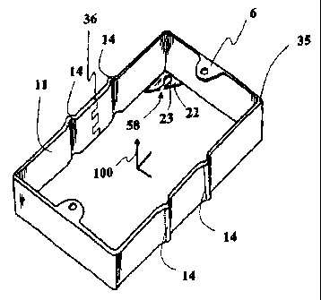
FIG. 7 illustrates in a top view the extending member 35
inserted into the adapting member 37 along the principal
axis of extension, which in this view is out of the page.
FIG. 7 shows the tapped or grooved end of a screw 40 as an
example of an elevating fastener with the screw 40 engaging
the upper bracket 22 and the lower bracket 38. The screw
40, preferably having a lock washer or grommet 41, is able
13
CA 02484132 2009-09-04
to snap into the lower bracket 38 through the lower lateral
access 57 and into the upper bracket 22 through the upper
lateral access 58. Also shown is the remaining region of
the ring 109 after snapping off the mounting tabs 106
attached to the ring member.
FIG. SA is a cross-sectional view of FIG. 7 at 8A
illustrating the engagement of the upper bracket 22 and the
lower bracket 38 via the elevating fasteners 40. Where
tapped screws are used 40, lock washers 41 are also
preferably used and grommets are used in alternative
embodiments. In an orientation where the head of the screw
40 is below the ring mounting plate 38, the end of the
screw distal from the head preferably has a grove whereby a
flat head screw driver for example may be used to rotate
the screw. Protrusions 14 are shown to run up and down,
that is, parallel with the axis of extension. FIG. BE
illustrates in cross-sectional view an alternative
embodiment having springs 34 inserted between the upper
brackets 22 and the lower brackets 38. The springs 34 are
preferably under compression to provide force to the
extending member 35 and work to aid in the extension
process. The orientation of the elevating fastener may be
reversed as is illustrated in FIG. 21 below. In those
embodiments of threaded screws having lock washers 41 or
grommets where the head of the screw is above the slider
mounting plate 22, a spring may be inserted between the
slider mounting plate 22 and the ring mounting plate 38
preferably in compression to increase the force in the
14
CA 02484132 2009-09-04
extending direction. Illustrated in FIG. 8C is an
alternative elevating fastener example that may be. used in
place of the single threaded screw. This alternative
elevating fastener is a double thread screw 803 having
threads in a first direction 804 above a median or
transition region 805 and threads in a direction opposite
806 the first direction below the median or transition
region 805. The double thread screw may be preferably
rotated using a flat head screwdriver placed in a grove 807
at a distal end.
An alternative embodiment of the present invention includes
a circular sliding member and either a rounded or square-
shaped adapting plate portions adapted to detachably attach
to an electrical box, for example. Oval sliding members are
accommodated in a fashion substantially similar to the
circular examples that follow. FIG. 9 illustrates the
circular sliding member 201 with electrical device mounting
plates 202 and a plurality of preferably linear protrusions
214 stamped into the sliding member wall preferably
parallel with the axis of extension as shown in this
example- The slider bracket, or upper bracket 203 connects
the slider with the mud ring member by way of an elevating
fastener. The upper bracket 203 has an aperture 204 which
may be tapped to engage an elevating fastener such as a
screw for example.
FIG. 10 illustrates an adapting circular ring 210 with a
circular base including at least one plug/switch mounting
CA 02484132 2009-09-04
plate 206 having a plate aperture 207, and in this example,
two plug/switch mounting plates 206 extending from the top
portion of the flange 280 of the ring 210. As an example of
the frangible device mounting plates, preferably
perforations 208 or creases allow the mounting plate 206 to
be snapped or worked off of the ring 210, or otherwise
removed from the ring 210, enabling the sliding member 201
to=be inserted into the adapting member 210 by way of the
flange aperture formed or otherwise bordered by the flange
inward side 250. The lower bracket 236 provides for the
connecting of the sliding member 201 via the elevating
fastener to the adapting ring. The lower bracket 238 has a
ring aperture 239 which may be tapped to engage an
elevating fastener such as a screw, where a preferred
embodiment has a smooth rather than threaded guiding
aperture 239. FIG. 11 illustrates an alternative mud ring
290 having a square base adapting plate 291 with an
adapting circular ring 210.
FIG. 12 illustrates in a top view an extending member 201
inserted into a ring member 210 showing the tapped end of a
screw 240 having a groove, where the screw 240 engages the
upper bracket 203. The protrusions 214 of the sliding
member 201 are in contact with the inner wall 250 of the
flange of the ring 210 which form the boundary of the ring
aperture and thereby provide electrical and mechanical
contact between the ring 210 and the sliding member 201.
Also shown is the remaining region of the ring 109 after
snapping off or otherwise removing the frangible device
16
CA 02484132 2009-09-04
mounting tabs 206 previously extending from the top edge of
the flange 280 of the ring member 210 into the aperture
formed by the flange 280 and substantially parallel to the
adapting plate portion 269of the mud ring or adapting
member 210. An alternative embodiment of the ring member
210 is made without electrical device mounting tabs. FIG.
13 illustrates in a perspective view the extending member
201 inserted into the adapting member 210 so that the
aperture 204, as illustrated in FIG. 9, of the upper
bracket 203 is aligned with the aperture 239, as
illustrated in FIG. 10, of the lower bracket 238. The lower
bracket 238 is shown extending into the well of an example
octagonal electrical box 270. Also shown is the screw 240
engaging the upper bracket 203 and the lower bracket 238.
FIGS. 14-17 illustrate an alternative embodiment of an
adapting ring 210 with a plurality of protrusions 215
preferably stamped into the ring wall. The Drotrusions of
the adapting ring 215 are in contact with the outer wall of
the sliding member 201 and thereby provide electrical and
mechanical contact between the ring 210 and the sliding
member 201. FIG. 14 illustrates, in a top view, the
alternative embodiment where the ring protrusions 215
contact the outer wall of the slider 201 and the slider
protrusions 214 contact the inner wall of the flange 280 of
the mud ring 210. In an alternative embodiment, the slider
201 does not have protrusions, so that the assembly
preferably relies upon the adapting ring protrusions 215
from the flange inner wall 250 for electrical connectivity.
17
CA 02484132 2009-09-04
FIG. 15 illustrates, in an isometric view, the alternative
embodiment where the ring protrusions 215 contact the outer
wall of the slider and the slider protrusions 214 contact
the inner wall of the flange 280 of the mud ring 210. FIG.
16 illustrates, in a top view, the alternative embodiment
where the ring protrusions 215 contact the outer wall of
the slider 201 and the slider protrusions 21.4 contact the
inner wall 250 of the flange 280 of the mud ring 290 having
a rectangular adapting plate 291 for detachably attaching
to a rectangular electrical box. Also illustrated is the
region of the flange remaining 109 after the removal of the
mounting plates 206 shown in FIG. 11_ FIG. 17 illustrates,
in an isometric view, an alternative embodiment of the mud
ring 290 adapted to detachably attach to a rectangular
electrical box 271 where the ring protrusions 215 contact
the outer wall of the slider 201 and the slider protrusions
214 contact the inner wall of the flange 280 of the mud
ring 290. FIG. 18 illustrates, in a top view, the
alternative embodiment where the slider protrusions 214
contact the inner wall 250 of the flange 280 of the mud
ring 290 having a rectangular adapting plate 291 for
detachably attaching to a rectangular electrical box. FIG.
19 illustrates, in an isometric view, an embodiment of the
mud ring 290 adapted to detachably attach to a rectangular
electrical box 271 where the slider protrusions 214 contact
the inner wall 250 of the flange 280 of the mud ring 290.
FIG. 20 is cross-sectional view of FIGS. 18 and 19 taken at
20, respectively, illustrating the mounting plate of the
18
CA 02484132 2009-09-04
ring 202 and the fastener 240 connecting with the bracket
surface of the sliding member 203 and the bracket surface
of the ring 238. The example slider protrusions 214 are
shown to run up and down in this view, that is, parallel to
the axis of extension. As previously illustrated in FIG.
8B, a spring 34 may be place between the washer 41 or
grommet and the slider mounting plate to increase extending
force. FIG. 21 illustrates in cross-sectional view an
alternative orientation of the elevating fastener 240. In
addition, a spring may be inserted between the slider mount
plate 203 and the ring mounting plat 238 to aid in the
slider extending force.
Many alterations and modifications may be made by those
having ordinary skill in the art without departing from the
spirit and scope of the invention. Therefore, it must be
understood that the illustrated embodiment has been set
forth only for the purposes of example and that it should
not be taken as limiting the invention as defined by the
following claims. While illustrated as a single assembly,
the adapting member and, as an assembly, the extending
member, are applicable to an array of attachable electrical
devices and the adapting member and the assembly are
applicable to an array of assemblies mounted to electrical
boxes of extended size (e.g., elongated rectangles
receiving several assemblies).
The words used in this specification to describe the
invention and its various embodiments are to be understood
19
CA 02484132 2009-09-04
not only in the sense of their commonly defined meanings,
but to include by special definition in this specification
structure, material or acts beyond the scope of the
commonly defined meanings. Thus if an element can be
understood in the context of this specification as
including more than one meaning, then its use in a claim
must be understood as being generic to all possible
meanings supported by the specification and by the word
itself.
The definitions of the words or elements of the following
claims are, therefore, defined in this specification to
include not only the combination of elements which are
literally set forth, but all equivalent structure, material
or acts for performing substantially the same function in
substantially the same way to obtain substantially the same
result- While the drawings reflect a electrical box, ring,
or adapting member, and the sleeve, or extending member,
all made of galvanized steel, the invention may be embodied
with members each made of plastic, preferably fire
resistant plastic, metal, preferably galvanized steel,
ceramic or combinations thereof. In those embodiments
having the electrical box, adapting member and extending
member each made of plastics and ceramics or combinations
thereof, it is preferred that electrical conductivity
maintained by reverse thread screws as extending fasteners.
In addition, the term electrical box is used generically to
refer to grounded electrical housing of three-dimensional
shapes including boxes of rectangular sides, boxes of
CA 02484132 2009-09-04
square sides, and boxes of cylindrical shapes with circular
or oval tops and bottoms or other shapes acceptable in the
electrical applications and the grounded electrical housing
may accommodate one or more plugs and or switches.
In addition to the equivalents of the claimed elements,
obvious substitutions now or later known to one with
ordinary skill in the art are defined to be within the
scope of the defined elements.
The claims are thus to be understood to include what is
specifically illustrated and described above, what is
conceptually equivalent, what can be obviously substituted
and also what essentially incorporates the essential idea
of the invention.
21