Note : Les descriptions sont présentées dans la langue officielle dans laquelle elles ont été soumises.
CA 02485471 2004-11-08
WO 03/095985 PCT/CA03/00655
METHOD AND PROBE FOR MEASURING
HYDRAULIC CONDUCTIVITY OF SOIL
FIELD OF THE INVENTION
The present invention relates to a probe for measuring hydraulic
conductivity of soil, and more particular to a method of use of the probe in
situ.
BACKGROUND
Groundwater contamination is a growing concern in the agricultural
and waste management industry. Seepage losses from animal-waste storages,
municipal lagoons, and industrial waste retention ponds including mine
tailings
retention ponds, are common sources of groundwater pollution. A livestock
operation produces large amounts of organic effluent and often is stored on
site.
Typically, the most feasible and cost effective method to store and or treat
organic waste is to contain the waste in a lagoon or reterition pond. The
bottom
of these lagoons is generally made from a semi-impermeable layer comprised of
synthetic or clayey soil material. In most cases, the cost of synthetic
impermeable liners is more expensive than compacted clay liners and therefore
the clay liners are used more often for agricultural waste management
applications.
The main concern relating to clay liners is their ability to properly
maintain a relatively impermeable barrier between the waste and the
surrounding
mafierial over a length of time without seepage losses that could impact the
groundwater quality in the area. When manure storage lagoons require
maintenance or are emptied for organic fertilizing purposes, they are usually
agitated to mix the solids that have settled out over a period of time. This
agitation process can loosen and partially remove the upper layer of the
saturated clay liner, which inevitably causes the deterioration in the liner
thickness and a less desirable hydraulic conductivity. The guidelines given by
the United States Environmental Protection Agency (EPA) for the thickness of a
clay finer is one metre and the hydraulic conductivity (K), cannot be greater
than
1 x 10⁻⁷ cm/s.
Estimation of soil hydraulic conductivity at a particular site is
challenging and expensive at times in order to produce acceptable results.
CA 02485471 2004-11-08
WO 03/095985 PCT/CA03/00655
-2-
Measuring the permeability of a saturated clay matrix is important in the
design of
lagoon liners. The ability to predict the rate of nitrate contaminant
transport is
vital information for evaluating future lagoon sites. Accurate estimates of
the
hydraulic conductivity act as a tool for monitoring existing sites.
There are a number of methods that are in use to measure the
saturated hydraulic conductivity of soils, but these are typically overly
expensive,
complicated, time consuming and/or produce false results. A sample can be
obtained as a core from the lagoon bottom, after pump out, and laboratory
tests
can estimate the hydraulic conductivity (K), however this disturbed specimen
may
not be a true representation of the in situ conditions. Pumping the storage
dry
would cause shrinkage cracks, which could create macropores and fissures,
which will act as preferential flow paths for contaminants. To protect the
integrity
of the clay liner, manure storages are never completely emptied during pump
out
and this makes it extremely difficult to obtain core samples from the bottom
covered with liquid manure slurry. Getting technicians to retrieve core
samples
under such conditions will be a difficult and time consuming task. Since the
manure storages are never emptied completely it is impossible to locate
problems by visual inspection by regulators. Currently, core samples are
obtained using drill rigs located on the frozen ice layer above the stored
manure.
However, this is limited to a small window of time during which the outside
temperatures remain below sub-zero temperatures (< -15 degrees Celsius) so
that the ice cover remains thick enough to support a drill-rig.
Another method commonly used to determine K is a standard
borehole pump test, but this intrusive method disturbs the thin upper organic
sludge-clay interface and exposes that portion of liner to an aerobic
environment.
Chemical reactions and biological interaction with the aerobic environment
changes the in situ characteristics of the liner. Also, the borehole pump test
is
more applicable to highly permeable aquifers. However, because of the low
hydraulic conductivity of compacted clay, the conventional borehole tests
cannot
be used efficiently for the lagoons. It is essential to develop an accurate
monitoring tool to determine a clay liners perfiormance over time in order to
CA 02485471 2004-11-08
WO 03/095985 PCT/CA03/00655
-3-
minimize seepage below retention ponds and lagoons to ensure the safety of
rural groundwater aquifers.
As noted above, hydraulic conductivity of soils is determined by a
number of techniques, but in practice, there are only three main methods:
laboratory tests, field tests and empirical methodologies (Domenico and
Schwartz
1997 pg.44). The theory of hydraulic conductivity, Darcy's Law and Horslev's
Method is reviewed in detail. An overview of electro-kinetics and how it
relates to
hydraulic conductivity is provided.
Most methods used to measure hydraulic conductivity are derived
from the fluid motion through porous media law known as Darcy's Law. This law
was named after a French civil engineer Henry Darcy whose experimental
methodology for measuring the rate of flow through a porous medium was
published in 1856. Darcy's experiment includes a cylinder of length (L)
containing a porous medium with manometers attached at either end to measure
the water pressure head as water passes through the column. From this simple
experiment, Darcy found that discharge Q, is proportional to the change in
head
pressure and inversely proportional to the length of the column containing the
porous media (Fetter 1994). From these relationships Darcy formulated the
Hydraulic conductivity constant K, which estimates the rate of flow through a
porous medium per unit hydraulic gradient per unit cross-sectional area..
Discharge is expressed in the general form Q= -KA(dh/dl), where Q is the
discharge (L3/T) and A is the cross sectional area through which the fluid
passes
and has units L2. The term (dh/dl) is referred as the hydraulic gradient,
which is a
ratio of the difference in head (h~-h2) between two points and the length
separating them (DL). The proportionality coefficient K represents the
hydraulic
conductivity, which has the same units as velocity L/T. The negative sign
represents the movement of a fluid in the direction of decreasing hydraulic
head
(Fetter 1994). The hydraulic conductivity is dependent on fluid properties
such as
density and kinematic viscosity as well as properties of the porous medium.
Domenico and Schwartz (1997) express the hydraulic conductivity
K, in terms of properties that characterize the fluid (water in this case) and
porous
medium (sand in this case). This relationship is expressed as
CA 02485471 2004-11-08
WO 03/095985 PCT/CA03/00655
-4-
K _ Nd ZPH~g _ kaPW~'
Where
N = Dimensionless shape factor of the sand particle
pW = Density of water at a specific temperature (M/L3)
g = Acceleration due to gravity (L/T2)
d = Mean grain diameter (L)
p= Dynamic viscosity of fluid (M/TL)
k; = Intrinsic permeability of the porous medium.(L2)
The intrinsic permeability k; is a property of the porous medium that
is equal to Nd2 in the given relationship. The intrinsic permeability is
independent
of the fluid properties and therefore is a direct measure of flow resistance
through
a medium. Given a particular fluid, the higher the permeability of a porous
homogeneous medium, the greater the ability to transmit flow.
The hydraulic conductivity can be determined in the laboratory
using several different techniques, but these methods lack the characteristics
of
in situ methods that minimally disturb the soils. Two of the most common
methods of determining hydraulic conductivity in the laboratory are Constant
Head and Falling Head methods.
The constant head permeameter method delivers a constant supply
of fluid to a porous medium to maintain a given pressure head. The hydraulic
_ LQ
H~cRz
conductivity is specified by the relationship:
where Q is the volume flow rate defined by the cross sectional area of the
tube
multiplied by the velocity of the fluid. The constant head permeameter is most
suitable for estimating the hydraulic conductivity of coarse sands and gravels
because of the high permeability of these materials, while the falling head
CA 02485471 2004-11-08
WO 03/095985 PCT/CA03/00655
-5-
permeameter is more appropriate for fine silt and clay like soils (Wanielista,
Kersten and Eaglin 1997).
The falling head permeameter uses a similar relationship for the
discharge Q. The falling rate of the wafer level in the stand pipe is
expressed by:
dla
Q=Av=~2
dl ~
Where,
v = falling head velocity.
And Darcy's Law can be applied to the soil column as:
Q ~zR K
After equating both of these equations and integrating, the hydraulic
conducfiivity for a falling head permeameter is represented by the following
relationship:
K~~"LIn H
~cR't HZ
where H~/H2 is the head ratio of initial to final head at a time t(s).
A flexible wall permeameter is a test chamber that contains a
porous medium, which is used for both the constant and falling head methods.
There are strict guidelines for laboratory procedures when acquiring and
testing a
porous material sample and are outlined by the American Society for Testing
and
Materials (ASTM D 5084 -90). The laboratory techniques discussed are
standard methods of determining K from small soil samples taken from the
field.
Field techniques are more accurate methods for estimating in situ
hydraulic conductivity. Small-scale lab tests are not representative of the
non=
uniformities, which are found in geological deposits under subsurface
conditions.
Examples of such naturally occurring non-uniformities are macro pores,
fissures
and small channels including worm and rodent holes. These soil structure
abnormalities are very challenging to duplicate in an experimental setting and
the
results from which therefore are only estimators of in situ hydraulic
conductivity.
CA 02485471 2004-11-08
WO 03/095985 PCT/CA03/00655
-6-
Daniel (1989) explains that in situ permeameters can be divided
into four categories. The first two categories are borehole and porous probe
permeameters that are used to measure low permeability soils and the other two
are infiltrometers and lysimeters that estimate K for permeable agricultural
type
soils.
The borehole or augerhole method is one of the most popular site
investigative and monitoring practices of estimating hydraulic conductivities
for
relatively shallow water tables. One of these techniques is called the
Hvorslev
Method or Slug test method, which drills out a standard borehole and inserts a
piezometer. In one variation, the piezometer may be installed into sand and
therefore does not require a sand pack around well screen to minimize entry
losses.
When the static water level (H) is measured, a unit volume of water
or metal slug is either introduced or removed out from the well. If a slug is
suddenly introduced, then the water level will rise to the initial falling
head Ho. As
the head decreases, the time is recorded until the wafer level returns close
to the
static level H. Water levels can be measured accurately inside the piezometers
with pressure transducers that measure the change in head pressure. The data
is then plotted where the natural logarithm of the ratio of H/Ho produces a
relatively straight line with respect to time. Hvorslev (1951 ) developed the
relationship between the measured hydrostatic head and the pore pressures in
the adjacent soil formation as water flowed info the piezometer. Hvorslev
noticed a fag time required to equilibrate the pressure difference assuming
that a
constant flow is maintained at the initial rate into the piezometer and found
that
the time lag was inversely proportional to the hydraulic conductivity of the
adjacent soil. The following equation relates time lag and K:
__A
T° FK
where, To = basic lag time for the head level to fall to 37 percent of the
initial wafer level;
F = shape factor which varies with borehole geometry; and
A = Cross sectional area of the piezometer.
CA 02485471 2004-11-08
WO 03/095985 PCT/CA03/00655
-7-
When the time lag is established and the shape factor is identified
for a particular piezometer or instrument, the above relationship can be
rearranged to solve for the hydraulic conductivity of the adjacent soil.
The borehole in situ methods have several limitations such as high
implementation costs, poor estimators of the vertical component of hydraulic
conductivity and the role of specific storage SS is completely ignored
(Demir,Z.
and Narasimhan, T.N. 1994). The specific storage is the amount of water
released or absorbed into storage per unit of volume of a porous medium per
unit
change in fluid head (Fetter,1994).
A similar borehole method uses the Boutwell Permeameter, which
measures both horizontal (Kh) and vertical (K") coefficients of permeability.
This
is an improvement from the previous method, but both methods measure a
relatively small volume of soil («1 m3) and can take any where from a few days
to weeks for silty-clay soils with K < 1x10⁻⁷ cm/s (Daniel, 1989).
Daniel (1989) describes and summarizes nine state of the art in situ
hydraulic conductivity estimation methods and instruments for compacted clay
soils and lists the advantages and disadvantages of each method. The common
element that plagues all in situ methods of estimating hydraulic conductivity
are
the errors caused by incomplete saturation of the soils (Daniel 1989).
In the laboratory there have been many efforts to relate measured
values of hydraulic conductivities to various properties of porous materials
(Domenico, P. A. and Schwartz, F.W. 1997).
Empirical methods are adequate for rough estimations of hydraulic
conductivities, but should be used only as theoretical tools rather than for
practical design applications.
Electro-osmosis is a mechanism, which induces a fluid to flow
through low permeable clayey soils. When elecfirodes are attached to a column
of saturated soil and an electrical potential gradient is applied across the
soil
sample, the fluid will move from the anode to the cathode. The fluid flow is
induced by the electric field applied to the soil sample (Yeung, A.T.,
Gopinath,
Sreekumar, Menon, Rajendra, M., Scott, T.B., Datla, Subbaraju. 1993). Water
CA 02485471 2004-11-08
WO 03/095985 PCT/CA03/00655
-$_
will move under the influence of an electrical potential gradient and the
electro-
osmotic flow rate can be expressed by the equation:
q~ _ -K~~E
where qe is the electro-osmotic flux (m/s); and
Ke is the electro-osmotic conductivity (m~N~s).
The electrical potential gradient is represented by VE and has units
V/m.
Since a hydraulic gradient is induced by exposure to an electric
field, a probe or device can be developed to estimate saturated hydraulic
conductivity by utilizing electro-osmotic behaviour of various soils.
SUMMARY
According to one aspect of the present invention there is provided a
method of measuring hydraulic conductivity in soil, said method comprising:
providing a probe having means for generating an electrical
potential gradient for causing fluid flow and pressure sensing means for
measuring changes in pressure;
inserting the probe into the soil;
measuring a first pressure condition within the soil using the
pressure sensing means of the probe;
applying an electrical potential gradient to the soil using the
electrical potential gradient means of the probe for an elapsed period of
time;
measuring a second pressure condition within the soil using the
pressure sensing means of the probe;
removing the application of electrical potential gradient to the soil at
the end of the elapsed period of time;
measuring the pore fluid pressure as a function of time during a
measured duration while the soil returns from the second pressure condition to
the first pressure condition; and
calculating hydraulic conductivity based upon a prescribed
relationship of hydraulic conductivity and the measured duration.
The method may include calibrating the probe to determine the
CA 02485471 2004-11-08
WO 03/095985 PCT/CA03/00655
_g_
prescribed relationship between hydraulic conductivity and the measured
duration prior to calculating the hydraulic conductivity.
The electrical potential gradient is preferably applied until a
pressure condition of the soil reaches a prescribed pressure in which the
prescribed pressure is an adjustable set point pressure. The electrical
potential
gradient is also preferably applied for a prescribed duration.
In some instances the method may include wetting the soil before
measuring the first and second pressure conditions. In this instance, the
probe
would include a water port for introducing water into the soil which is to be
sealed
before measuring the first and second pressure conditions induced by the
electro-osmotic method. A pressure condition of the soil should become
constant
after wetting the soil before measuring the first and second pressure
conditions.
In further instances, the method may include bleeding air
surrounding the pressure sensing means within the soil before measuring the
first
and second pressure conditions. In this instance, the probe preferably
includes
an air port for removing air from the soil surrounding the pressure sensing
means. The method includes sealing the air port before measuring the first and
second pressure conditions when an air port is provided.
When the probe includes two electrical potential sensors at
prescribed spaced locations within the electrical gradient generated by the
electrical potential gradient means, the method may include measuring
electrical
potential across the potential electrodes and calculating the electrical
conductivity
of the soil. The soil is preferably wetted before measuring the first and
second
pressure conditions if the calculated electrical conductivity indicates the
soil is
d ry.
By recording the elapsed period of time of the electrical potential
gradient, the electro-osmotic conductivity can be calculated based upon the
elapsed period of time and a difference in magnitude between the first and
second pressure conditions.
The method is particularly suited for application in situ into clay soil
beneath a retention pond.
For proper sealing of the lining of a retention pond after
CA 02485471 2004-11-08
WO 03/095985 PCT/CA03/00655
-10-
measurement, the method preferably includes the steps of:
a) providing a probe insertion tube for slidably receiving the probe
therethrough;
b) inserting the probe insertion tube into the soil prior to insertion of
the probe;
c) inserting the probe into the soil by inserting the probe through the
probe insertion tool;
d) removing the probe from the probe insertion tube subsequent to
measurement of the first and second pressure conditions;
e) introducing soil sealing material through the probe insertion tube
to fill a cavity in the soil formed by the probe; and
f) removing the probe insertion tube from the soil.
A suitable soil sealing material may comprise bentonite pellets.
According to a further aspect of the present invention there is
provided a probe for measuring hydraulic conductivity in soils, the probe
comprising:
a housing being suitably shaped for insertion into the ground;
electrical potential gradient means for generating an electrical
potential gradient in the ground surrounding the housing; and
pressure sensing means for measuring changes in pressure in the
porewater within the ground.
The housing preferably comprises an elongate tubular member
having a pointed soil penetrating end in which the electrical potential
gradient
means and the pressure sensing means being located adjacent the pointed soil
penetrating end.
The electrical potential gradient means may comprise first and
second electrodes insulated from one another at spaced locations on the
housing
and an electrical power supply coupled therebetween.
When the housing extends in a longitudinal direction between an
exposed end and a soil penetrating end, the first and second electrodes are
preferably spaced apart from one another in the longitudinal direction of the
housing.
CA 02485471 2004-11-08
WO 03/095985 PCT/CA03/00655
-11-
The first electrode may be coupled to a pointed end cap at the soil
penetrating end of the housing and the second electrode may be coupled to side
walls of the housing when the pointed end cap is insulated with respect to the
side walls of the housing.
There may be provided two electrical potential sensors supported
on an insulated portion of the housing at prescribed spaced locations within
the
electrical gradient generated by the electrical potential gradient means.
There may be provided a plurality of apertures in the housing for
communication with an internal cavity of the housing supporting the pressure
sensing means therein,
There may be provided a remotely operated mechanism to cover
the plurality of apertures in the housing to prevent clogging of the apertures
during insertion and retrieval so as to maintain communication with an
internal
cavity of the housing supporting the pressure sensing means therein.
The mechanism to cover the plurality of apertures should be
operable from a remote location.
The pressure sensing means preferably comprises a pressure
transducer.
When the housing extends in a longitudinal direction between an
exposed end and a soil penetrating end, an air port may communicate between
the exposed end of the housing and the internal cavity of the housing. The air
port preferably includes a valve for selectively sealing the air port in a
closed
position.
There may also be provided a water port communicating between
the exposed end of the housing and the internal cavity of the housing, which
also
includes a valve for selectively sealing the water port in a closed position.
For insertion into the ground there is provided an elongate probe
insertion tube for receiving the housing therein having a soil penetrating end
formed of resilient material permitting the pointed end of the housing to be
penetrated therethrough.
BRIEF DESCRIPTION OF THE DRAWINGS
In the accompanying drawings, which illustrate an exemplary
CA 02485471 2004-11-08
WO 03/095985 PCT/CA03/00655
-12-
embodiment of the present invention:
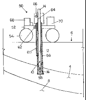
Figure 1 is an elevational view of the probe in use at a retention
pond.
Figure 2 is an isometric view of the probe.
Figure 3 is a longitudinal sectional view of the probe.
Figure 4 is a cross sectional view along the line 4-4 of Figure 3.
Figure 5 is an exploded isometric view of the probe.
DETAILED DESCRIPTION
Referring to the accompanying drawings, there is illustrated a
hydraulic conductivity probe generally indicated by reference numeral 10. The
hydraulic conductivity probe is intended for use in measuring the hydraulic
conductivity of soil in situ. The probe is particularly useful for measuring
hydraulic conductivity of soil linings 4 of retention ponds 6, including
municipal
lagoons and manure storages and the like, of the type which do not include a
geo-membrane, but rather rely generally on clay content of the surrounding
soil to
resist seepage into the surrounding environment 8.
The probe 10 generally includes a housing 12 in the form of an
elongate rigid tubular member formed of conductive material. The housing
extends in a longitudinal direction between an exposed end 14 and a soil
penetrating end 16.
An insulator 18 is mounted on the soil penetrating end 16 of the
housing. The insulator 18 ~ is a cylindrical member formed of rigid insulating
plastic material. The insulator includes a stepped portion 20 at an inner end
thereof having a reduced diameter for snugly fitting within the interior of
the
tubular housing 12 at the soil penetrating end 16 thereof. An exterior
diameter of
the insulator 18 is arranged to mount flush with the walls 22 of the housing.
A pointed end cap 24 is provided at the soil-penetrating end of the
housing for being supported on the insulator 18 so as to be electrically
isolated
with respect to the walls 22 of the housing. The end cap 24 is generally
conical
in shape, being formed of rigid conductive material and tapering towards an
apex
for penetration into the soil. A projection at the inner end of the end cap 24
mates with a corresponding recess 26 in the insulator 18 for securement of the
CA 02485471 2004-11-08
WO 03/095985 PCT/CA03/00655
-13-
end cap to the insulator. An outer diameter of the end cap at a base thereof
mounts flush with the insulator 18 and the walls 22 of the housing.
The insulator is divided into an upper portion 28 and a lower portion
29. The upper portion 28 of the insulator 18 includes the stepped portion 20
noted above, so as to be supported within the tubular housing to span the
interior
of the tubular housing in sealing engagement with the walls 22 thereof.
Hydraulic
barriers such as O-rings are used between the walls 22 of the housing and the
stepped portion 20 of the insulator received therein.
The upper and lower portions 28 and 29 of the insulator 18 have the
same exterior diameter and are screwed together in an end to end
configuration.
An internal cavity 30 is defined at the intersection of the upper and lower
portions
when coupled together. The internal cavity 30 is located intermediately in the
insulator 18 at spaced positions from both the walls 22 of the tubular housing
and
the end cap 24.
A water port 32 is provided in the form of a tube that communicates
through the upper portion of the insulator 18, in sealed engagement therewith,
from the exposed end of the housing to the internal cavity 30. The water port
32
permits water to be added to the soil at the internal cavity 30 adjacent the
soil
penetrating end of the housing for use in instances when the ground is not
sufficiently saturated with water. A valve 34 selectively communicates with
the
water port 32 at a point of communication with the internal cavity 30 which is
operable to selectively seal the water port closed to prevent communication of
the
water port with the internal cavity when the valve 34 is in its closed
position.
Similarly an air port 36 is provided in the form of a tube for
communication through the upper portion of the insulator 18 between the
internal
cavity 30 and the exposed end of the housing. The air port 36 includes a valve
38 for selectively sealing the port closed as desired. The valves 38 and 34
may
be operated by conventional means including solenoid actuation for example.
The air port 36 is useful for drawing air out of the internal cavity 30 before
measurement of hydraulic conductivity to ensure that the surrounding soil is
saturated with water.
A wiring conduit 40 is provided for communication from the exposed
CA 02485471 2004-11-08
WO 03/095985 PCT/CA03/00655
-14-
end of the housing through the insulator 18, in sealed engagement therewith,
to
electrical components of the probe. The wiring conduit 40 comprises a sealed
tube, which couples an electrical power source of the probe between a first
current electrode 42A and a second current electrode 42B of the probe. The
second electrode 42B is coupled to the walls 22 of the housing so that the
conductive material of the housing acts as a current electrode. The first
electrode
42A is coupled to the end cap 24 which is also formed of conductive materials
so
that the end cap acts as the other current electrode. The current electrodes
of
the probe which act as cathode and anode respectively, are spaced apart in a
longitudinal direction of the housing by the insulator 18 so as to maximise
spacing between the two. When the probe is supported in an upright
orientation,
the anode and cathode are vertically spaced apart. Another variation for the
upright orientation is the horizontal placement of the electrodes to test for
anisotropy of the soil.
The wiring conduit 40 further communicates wiring therethrough for
communication with electrical potential sensors 44A and 44B at longitudinally
spaced locations within the insulator 18 between the anode and cathode of the
probe. The electrical potential sensors 44A and 44B are spaced apart from one
another at a prescribed spacing in the longitudinal direction of the housing
between the side walls 22 and the end cap 24 of the housing. The electrical
potential sensors serve to determine the electrical potential at two locations
at a
prescribed spacing within an electrical potential gradient generated by the
first
and second current electrodes, also referred to as the anode and cathode, when
the power source is activated. This electrical potential difference can be
used to
calculate the electrical conductivity of the soil and pore fluid adjacent to
the
insulating material 18. The electrical conductivity information is used
indirectly to
assess the saturation status of the soil adjacent to the insulating material
18.
The conduit 40 also receives wiring which couples to a load sensor
45, in the form of a load cell located within the recess 26 of the insulator
which
mounts the cap 24 thereon in a manner so as to record pressure applied to the
free end of the cap 24 in the longitudinal direction of the probe as the probe
is
inserted into the ground. The load sensor is used to monitor the penetration
CA 02485471 2004-11-08
WO 03/095985 PCT/CA03/00655
-15-
resistance similar to a penetrometer. This will help prevent damage to the
probe
if it came in contact with an impenetrable barrier such as a rock for example.
A pressure transducer 46 is mounted within the upper portion of the
insulator in communication with the internal cavity 30 for measuring pressure
changes within the cavity 30 while being shielded within the interior walls of
the
housing. The insulator 18 ensures that the pressure transducer is isolated
from
the walls of the housing which are charged. The transducer 46 provides
continuous monitoring of pressure within the cavity and permits these readings
to
be displayed at the exposed end of the housing by a suitable display coupled
thereto.
A plurality of apertures 48 are provided at spaced circumferencial
locations about an exterior wall of the insulator 18 at the intersection of
the upper
and lower portions thereof for communication with the internal cavity 30. The
apertures may be formed integrally in either of the upper or lower portions of
the
insulator 18. The apertures permit surrounding water within the soil to
communicate with the cavity so that pressure changes measured by the pressure
transducer 46 within the cavity 30 correspond to surrounding pressures of
water
within the soil about the housing surrounding the cavity 30.
As illustrated in Figure 1, an insertion mechanism 50 may be
provided to assist insertion of the probe into the soil and to act as conduit
for
introducing material to seal the hole, created by the probe, at the end of the
test.
In the illustrated embodiment, the insertion mechanism 50 is supported on a
floating platform 52 including pontoons 54 for floating on a retention pond 6
in
which the lining 4 is to be tested. The floating platform 52 is equipped with
suitable a suitable anchoring mechanism, for example one or more conventional
anchors or a tie down system for anchoring the platform at a fixed location
within
a body of water,
The insertion mechanism includes a probe insertion tube 56 in the
form of an elongate tubular member formed of rigid material which is suitably
sized to receive the housing 12 of the probe 10 slidably therethrough. A
rubber
end cap 58 is provided which spans a soil penetrating end of the probe
insertion
tube to prevent accumulation of soil and water within the tube as the tube is
CA 02485471 2004-11-08
WO 03/095985 PCT/CA03/00655
-16-
inserted into the ground. A rack 60 is provided alongside the tube for meshing
with a pinion gear 62 driven by a respective motor ,to selectively drive the
tube
down into the ground and back up again by reversing the motor. The housing of
the probe 10 may similarly include a rack 64 alongside thereof for meshing
with a
pinion gear 66 driven by a respective motor to selectively drive the probe
relative
to the tube, down through the tube 56 to pierce the end cap 58 once the tube
is in
position within the lining of the pond.
A suitable control mechanism 68 permits the probe to be operated
remotely from a location separate from the platform to insert and retrieve the
probe, as well as subsequently seal the hole in the lining left by the probe.
The
control mechanism is coupled to all of the electrical components. of the probe
for
storing data measured by the probe for later retrieval. The load sensor 45
communicates through the control mechanism 68 with the insertion mechanism in
order to selectively disable the insertion mechanism in the event that
excessive
pressure is recorded by the load sensor due to a rock or other debris for
example
being impacted in the path of insertion of the probe. The load sensor 45 will
give
data similar to a penetrometer. This information will also be used to
calculate the
depth of insertion beneath the compacted clay layer as well as provide
information about soil layer densities.
The control mechanism includes a data display which gives a direct
read-out of the hydraulic conductivity both in metric and imperial units. The
display also has the capability to store data for down-load at a later time.
In
addition to electrical conductivity readings, the display will show
penetration
resistance readings as well. An audible and/or visible signal, for example
beeps
and/or flashing lights, are provided on the display during the data
acquisition
process to indicate thafi the probe is functioning properly.
A sealing mechanism 70 is also supported on the platform, which is
suitably arranged to dispense bentonite pellets down through the tube 56 upon
removal of the probe 10 for sealing of the hole left by the probe. A tamping
rod
similar to the shape of the probe 10 is used to push the bentonite into the
resulting cavity left by the probe after it has been completely retracted from
the
hole. The tamping rod will be located parallel to the probe 10 and will be
moved
CA 02485471 2004-11-08
WO 03/095985 PCT/CA03/00655
-17-
into the position of the test hole once the probe 10 is retracted completely.
Prior to measurement of hydraulic conductivity, experiments may be
performed with the probe in different known soil types having known hydraulic
conductivity to permit calibration of the probe and to determine constants of
the
relationship between hydraulic conductivity and a measured duration of time
for
pressure at the cavity to vary between first and second pressure conditions,
previously induced by electro-osmotic flow, under a hydraulic potential
pressure
gradient.
Also prior to measurement of hydraulic conductivity it may be useful
to determine the electrical conductivity of the soil at the site of
measurement, as
an indication of the moisture contenfi of the soil. This is accomplished by
first
inserting the probe into the soil as noted above at which point the electrical
potential gradient between the cathode and anode is established. While the
electrical potential gradient is being applied, electrical potential
difference at the
sensors 44 is measured at spaced positions within the gradient. Electrical
conductivity can then be calculated using the two known electrical potentials
and
the known prescribed spacing of the points of measurement in a known
generated electrical potential gradient. if results of the measured electrical
conductivity indicate that the soil is too dry, water may be added through the
water port 32 to the soil surrounding the cavity 30 by appropriately
controlling the
valve 34 of the water port.
The compacted clay liners remain saturated beneath lagoons and
manure storages, however, in other applications it may be desirable to add
water
regardless of electrical conductivity measurements in order to ensure that the
surrounding soil is properly saturated with water. Before measurement of
hydraulic conductivity it is also important that any air within the cavity 30
and
surrounding soil be removed by opening the corresponding valve of the air port
36 or manually fill the cavity prior to insertion of the probe 10. The valves
connecting both the air and water ports to the cavity must be sealed closed
before proceeding with any measurements. It is also desirable to wait for
pressure as measured by the transducer 46 to stabilise at a constant value
when
water has been added before proceeding with the measurement of hydraulic
CA 02485471 2004-11-08
WO 03/095985 PCT/CA03/00655
conductivity.
Measurement of hydraulic conductivity begins by first measuring
pressure as determined by the pressure transducer 46 within the cavity and
recording this pressure as a first pressure condition. The electrical
potential
gradient is then applied by the power source coupled between the cathode and
anode until a prescribed pressure as measured by the transducer 46 is reached.
The prescribed pressure is preferably a set point pressure, which is
adjustable in
order to prevent the electrical gradient from being applied too long. If the
prescribed pressure takes too long to achieve, a duration threshold may be
preferable for discontinuing the applied electrical potential gradient before
soil
properties are affected. Alternatively a prescribed duration for application
of the
electrical potential gradient may be desirable.
Once the electrical potential gradient has been removed, pressure
is again measured within the cavity 30 by the transducer 46 and recorded as a
second pressure condition. The measured duration is then recorded for pressure
of water within the cavity to return from the second pressure condition to the
first
pressure condition under hydraulic potential gradient. The hydraulic
conductivity
may then be calculated using the prescribed relationship between hydraulic
conductivity and the measured duration.
The probe readings should be restricted to one or two electrical
pulse applications at any given location. ,
In further applications, the electro-osmotic conductivity may also be
determined by recording the duration for which the electrical potential
gradient is
applied in addition to measuring the respective first and second pressure
conditions at the start and finish of the recorded duration of the application
of the
electrical potential gradient.
In operation, the gradient causes a net flow of water in the
surrounding soil from the cathode at the end cap 24 to the anode at the walls
22
of the housing so that there is produced a net flow of water into the cavity
30 in
the housing. When the electrical potential gradient is removed, the decrease
in
pressure of water in the cavity as produced by the net out-flow due to
pressure
dissipation is recorded ' by the transducer and is used for establishing the
CA 02485471 2004-11-08
WO 03/095985 PCT/CA03/00655
-19-
hydraulic conductivity of the soil. The probe is ideally used in soils having
a clay
content of at least five percent.
As noted above, the probe can be used to measure fihe hydraulic
conductivity of the clayey soil beneath manure storages, municipal lagoons and
other retention ponds that do not have geo-membrane liners. Hydraulic
conductivity of the soil can be used to estimate the seepage through it. There
are
no in situ methods currently available for measuring the hydraulic
conductivity of
soils beneath manure storages and lagoons. The law requiring minimal seepage
therefore, . cannot be reliably enforced once the manure storage has been in
operation. The probe will also be of interest to soil scientists, engineers
who are
dealing with soil physical properties. The probe can be used as a tool for
periodically monitoring the integrity of the clay finer beneath earthen manure
storages, municipal lagoons, retention ponds for industrial waste etc. It can
also
be used, for measuring the hydraulic conductivity of saturated soils in situ.
The probe operates because clay particles in the soils are
negatively charged and usually attract positively charged ions in the pore
fluid.
When a DC electrical potential gradient is applied to the soil, the positively
charged ions will move towards the cathode 24, which comprises the negative
electrode, and the negatively charged ions will move towards the anode 22,
which comprises the positive electrode. However, the positive ions, being
larger,
tend to drag more water molecules along with them compared to the negative
ions. As a result there is a net flow of water towards the cathode. This net
flow is
called electro-osmotic flow. The probe uses this principle to initiate a small
quantity of net flow towards the cavity containing the pressure transducer,
which
monitors the fluid pressure in the probe cavity. When the DC electrical
potential
gradient is removed, the inequality in fluid pressure created in the vicinity
of the
probe will tend to equalize by fluid flow in the reverse direction under
hydraulic
gradients. As the fluid flows in the reverse direction under hydraulic
gradients,
the pressure transducer will measure a decline in pressure within the cavity.
The
rate of decline of the pressure of fluid in the cavity is directly
proportional to the
hydraulic conductivity of the soil surrounding the probe. A probe constant can
be
established by calibrating in soils with known saturated, hydraulic
conductivity.
CA 02485471 2004-11-08
WO 03/095985 PCT/CA03/00655
-20-
The time rate of change of pressure and the probe constant information is used
by a module within the meter to calculate and display the hydraulic
conductivity of
the soil surrounding the probe. Since the water volumes are small the
measurement time is fast. The application of electro-kinetic principles to
move
the water towards the pressure sensing area of the probe is unique in this
method. The concept behind the electronic conversion of the response from the
sensor to intelligible hydraulic conductivity readings is unique.
Again as noted above, additional features include potential
electrodes 44A and 44B which can be used to measure the electrical
conductivity
of the soil using the four-point electrode method. This information is useful
for
getting a feel for the ionic concentration in the pore water. It can also
indirectly
indicate whether the soil surrounding the tip is dry or wet. If the soil is
dry, then
water could be introduced through the tubes prior to measurement. One tube is
used to introduce the water into the probe cavity and the other tube is used
to
bleed trapped air in the cavity. The air ~ bleed is necessary for the optimum
performance of the pressure transducer.
Hydraulic conductivity refers to the ability of soil to allow water
movement. In sewage lagoons, for example, it is important to determine
hydraulic
conductivity of the lagoon lining in order to determine the degree of seepage
from
the lagoon. Current methods of measuring hydraulic conductivity require the
removal of a core sample from the clay underneath the lagoon, which is then
transported back to the laboratory for the testing. There is currently no
feasible
method for measuring hydraulic conductivity of lagoon lining, making it
impossible
to enforce government regulations regarding seepage of sewage into the
groundwater.
The method disclosed herein can quickly determine the hydraulic
conductivity of sail. This method and the probe 10 are particularly useful in
applications such as sewage lagoons, in which a core sample is difficult to
obtain.
The method involves using the electro-osmotic conductivity of clay to draw up
minute amounts of water into a pressure sensing device, and then removing the
electrical stimulus, allowing the water to recede. The rafie at which the
water
flows back into the soil (monitored by pressure transducers) is proportional
to the
CA 02485471 2004-11-08
WO 03/095985 PCT/CA03/00655
-21 -
hydraulic conductivity of the soil.
The probe 10 applies the above principle, in the form of a telescopic
probe, approximately 2 inches or less in diameter, with a cone-shaped tip (3
inches in length) for penetration into the ground. As described above, a large
water-tight insertion tube 56 with a rubber end is first lowered through the
water
or sewage to the clay bed. The probe is then passed through the tube and
punctures the rubber end, passing into the ground. An electrical potential
gradient is then applied to the tip of the probe, drawing up approximately 5-
500
pL water. This amount of water is minute enough to allow fast measurement of
the hydraulic conductivity, while not disturbing the soil composition. The
electrical gradient is then removed, and the pressure dissipates when water
moves back into the clay. This measurement is much faster than the current
method of laboratory testing; as such a small quantity of water is used,
allowing
the water to dissipate more quickly. A pressure transducer is located within
the
probe and the change in pressure of the water over time can be used to
calculate
the hydraulic conductivity of the clay. In this manner, sewage lagoons may be
monitored on site for the ability of sewage to seep from the lagoon.
Anywhere the hydraulic conductivity of soils information is needed,
this probe can be used. For example, it can be used in the petroleum industry
to
assess the hydraulic conductivity of the formation. Oil movement in formations
can be predicted by measuring the water movement through oil-bearing
formations. At present, the oil industry measures this parameter in the
laboratory
using cores drilled from the formations. The in situ method might be more
advantageous because it is fast and a lot less expensive.
While one embodiment of the present invention has been described
in the foregoing, it is to be understood that other embodiments are possible
within
the scope of the invention. The invention is to be considered limited solely
by the
scope of the appended claims.
CA 02485471 2004-11-08
WO 03/095985 PCT/CA03/00655
-22-
REFERENCES
1. American Society for Testing and Materials (ASTM). D 5084 -90 .
Standard test method for measurement of hydraulic conductivity of saturated
porous materials using a flexible wall permeameter. Annual Book of ASTM
Standards.
2. Daniel, E. David. 1989. In situ hydraulic conductivity tests for
compacted clay. Journal of Geotechnical Engineering, Vol. 115, No. 9 Pg. 1205-
1226 OASCE.
3. Demir,Z. and Narasimhan, T.N. 1994. Improved interpretation of
Hvorslev tests. Journal of Hydraulic Engineering, Vol. 120, No.4. Pg.477-494
4. Domenico, P. A. and Schwartz, F.W. 1997. Physical and Chemical
Hydrogeology, second edition. John Wiley & Sons, Inc.
5. Fetter, C.W. 1994. Applied Hydrogeology, Third edition. Prentace
Hall.
6. Hvorlsev, M.J. 1951. Time Lag and Soil Permeability in Ground
Water Observations. Corps of Engineers, U.S. Army. Bulletin no.36. Waterways
Experiment Station.
7. Wanielista, M., Kersten, R. and Eaglin, R. 1997. Hydrology -Vllater
Quantity and Quality Control, Second edition. John Wiley & Sons, Inc.
8. Yeung, A.T., Gopinath, Sreekumar, Menon, Rajendra, M., Scott,
T.B., Datla, Subbaraju. 1993. Electro-kinetic extraction of contaminants form
polluted soil. Waste Managerhent Proceedings of the Gulf Coast Hazardous
Substance Reasearch Center's 1993 Symposium on Emerging Technologies:
Metals, Oxydation, and Separation. Vol. 13, No.S-7. Pg 539-540.
All documents and publications referred to or mentioned in the
foregoing are incorporated herein by reference.