Note : Les descriptions sont présentées dans la langue officielle dans laquelle elles ont été soumises.
CA 02485765 2004-10-22
SPOKE PERMANENT MAGNET ROTORS FOR ELECTRICAL MACHINES AND
METHODS OF MANUFACTURING SAME
BACKGROUND OF THE INVENTION
The present invention relates to electric machines, and more particularly to
spoke
permanent magnet rotors for use in electric motors.
Spoke permanent magnet rotors generally include a plurality of permanent
magnets
radially arranged around a shaft. The permanent magnets are magnetized
tangentially,
through the thickness of the permanent magnet, either before or after
insertion into the rotor.
Magnetic flux generated by the permanent magnets is collected and concentrated
by ferro-
magnetic pole pieces. Often, the pole pieces are utilized to retain the
permanent magnets.
Some examples of spoke permanent magnet rotors are disclosed in U.S. Patent
Nos.
4,631,807; 5,140,211; 5,157,297; 5,200,662; and 5,463,262.
Spoke permanent magnet rotors have a natural flux concentration capability
because
two circumferentially adjacent permanent magnets contribute to the air-gap
flux for each
rotor pole. This flux concentration capability allows the air-gap magnetic
flux density to be
higher than the flux density of each permanent magnet that contributes to the
air-gap
magnetic flux density. Accordingly, electric motors that include spoke
permanent magnet
rotors often have a high specific torque output. This translates to a smaller
overall weight
and lower material cost for a given rating of electric motor. Further, based
on the radial
arrangement of the permanent magnets, the permanent magnets are less likely to
become
demagnetized. Therefore, rated operation close to the maximum energy product
is possible
without the risk of demagnetization of the permanent magnets under fault
conditions.
Operation at a maximum energy product ensures optimum utilization of the
permanent
magnets. This translates to lower material costs for a given rating of
electric motor.
Despite the above-mentioned advantages of spoke permanent magnet rotors, only
a
relatively small number of spoke permanent magnet rotors are produced
worldwide. One
limiting factor for high volume production is the complicated construction
required to reduce
or eliminate the permanent magnet flux leakage from the radially inward
portions of the
permanent magnets towards the magnetic shaft. Another limiting factor is the
complicated
construction required to retain the permanent magnets and the pole pieces in
the rotor during
normal operation of the electric motor. A new spoke type permanent magnet
rotor that
provides enhanced performance and reduced costs would be welcomed by those in
the art.
CA 02485765 2012-11-13
67363-1348
- 2 -
SUMMARY OF THE INVENTION
According to one aspect of the present invention, there is provided a rotor
assembly for an electric motor, the rotor assembly comprising: a spoke
permanent magnet
rotor having an axis of rotation, permanent magnet material circumferentially
surrounding the
axis of rotation to form a circumferentially surrounding portion of permanent
magnet material
and extending outwardly relative to the axis of rotation to form a plurality
of outwardly
extending portions of permanent magnet material, the circumferential portion
defining a first
interface surface, and ferro-magnetic material positioned adjacent to the
outwardly extending
portions of permanent magnet material and including an outer surface and a
second interface
surface formed inward of the outer surface that engages the first interface
surface, the first
interface surface and second interface surface arranged to inhibit outward
radial motion of the
ferro-magnetic material; and a shaft supporting the spoke permanent magnet
rotor for rotation
about the axis of rotation.
According to another aspect of the present invention, there is provided a
rotor
assembly for an electric motor, the rotor assembly comprising: a permanent
magnet rotor
having an axis of rotation, a center portion of permanent magnet material, a
plurality of
angularly spaced spoke portions of permanent magnet material extending
outwardly from the
center portion of permanent magnet material, and ferro-magnetic material
positioned between
the angularly spaced spoke portions of permanent magnet material; and a shaft
supporting the
permanent magnet rotor for rotation about the axis of rotation, wherein the
ferro-magnetic
material forms a plurality of pole pieces, and wherein the permanent magnet
material includes
plastic bonded permanent magnet material injection molded around the pole
pieces, wherein
the permanent magnet material and the ferro-magnetic material have an
interface
therebetween that prevents the ferro-magnetic material adjacent to the
interface from moving
outwardly during rotation of the spoke permanent magnet rotor about the axis
of rotation.
According to still another aspect of the present invention, there is provided
a
rotor assembly for an electric motor, the rotor assembly comprising: a spoke
permanent
magnet rotor having an axis of rotation, permanent magnet material extending
outwardly
CA 02485765 2012-11-13
67363-1348
- 2a -
relative to the axis of rotation to form a plurality of outwardly extending
spoke portions of
permanent magnet material, at least one of the plurality of spoke portions
defining a first
interface surface, the permanent magnet material including permanent magnet
powder
compacted using an electromagnetic compaction process, and ferro-magnetic
material
positioned adjacent to the outwardly extending spoke portions of permanent
magnet material
and including an outer surface and a second interface surface formed inward of
the outer
surface that engages the first interface surface, the first interface surface
and second interface
surface arranged to inhibit outward radial motion of the ferro-magnetic
material; and a shaft
supporting the spoke permanent magnet rotor for rotation about the axis of
rotation.
According to yet another aspect of the present invention, there is provided a
method of constructing a rotor assembly for an electric motor, the method
comprising:
compacting permanent magnet powder and ferro-magnetic powder using an
electromagnetic
compaction process to form a spoke permanent magnet rotor, the compacted
permanent
magnet powder forming a center portion of permanent magnet material and a
plurality of
spoke portions of permanent magnet material extending outwardly from the
center portion of
permanent magnet material, wherein at least one of the center portion and one
of the plurality
of spoke portions defines a first interface surface, and the compacted ferro-
magnetic powder
forming a plurality of pole pieces, each pole piece being positioned between a
respective set
of circumferentially adjacent spoke portions of permanent magnet material and
including an
outer surface and a second interface surface formed inward of the outer
surface; engaging the
first interface surface and the second interface surface to inhibit outward
radial motion of the
ferro-magnetic pole pieces; and supporting the spoke permanent magnet rotor on
a shaft for
rotation about an axis of rotation.
According to a further aspect of the present invention, there is provided a
rotor
assembly for an electric motor, the assembly comprising: a spoke permanent
magnet rotor
having an axis of rotation, permanent magnet material extending outwardly
relative to the axis
of rotation to form a plurality of outwardly extending spoke portions of
permanent magnet
material, at least one of the plurality of spoke portions defining a first
interface surface, ferro-
magnetic material forming a plurality of pole pieces, each pole piece being
positioned
CA 02485765 2012-11-13
67363-1348
- 2b -
between a set of circumferentially adjacent outwardly extending spoke portions
of permanent
magnet material, at least one of the pole pieces including a second interface
surface that
engages the first interface surface to inhibit outward radial motion of the at
least one pole
piece, the permanent magnet material including injection molded plastic bonded
permanent
magnet material; and a shaft supporting the spoke permanent magnet rotor for
rotation about
the axis of rotation.
According to yet a further aspect of the present invention, there is provided
a
method of constructing a rotor assembly for an electric motor, the method
comprising:
providing a plurality of ferro-magnetic pole pieces; injection molding plastic
bonded
permanent magnet material to form a spoke permanent magnet rotor, the
injection molded
plastic bonded permanent magnet material forming a center portion of permanent
magnet
material and a plurality of spoke portions of permanent magnet material
extending outwardly
from the center portion of permanent magnet material, and each pole piece
being positioned
between a respective set of circumferentially adjacent spoke portions of
permanent magnet
material; interlocking the permanent magnet material and the ferro-magnetic
pole pieces to
inhibit radially outward movement of the ferro-magnetic pole pieces with
respect to the
permanent magnet material; and supporting the spoke permanent magnet rotor on
a shaft for
rotation about an axis of rotation.
Some embodiments may provide spoke permanent magnet rotors that provide
enhanced performance and reduced costs.
In one embodiment, there is provided a rotor assembly for an electric motor.
The rotor assembly includes a spoke permanent magnet rotor and a shaft
connected thereto.
The spoke permanent magnet rotor has an axis of rotation, permanent magnet
material, and
ferro-magnetic material. The permanent magnet material circumferentially
surrounds the axis
of rotation to form a circumferentially surrounding portion of permanent
magnet material.
The permanent magnet material also extends outwardly relative to the axis of
rotation to form
a plurality of outwardly extending portions of permanent magnet material. The
ferro-
magnetic material is positioned adjacent to the outwardly extending portions
of permanent
CA 02485765 2012-11-13
67363-1348
- 2c -
magnet material. The shaft supports the spoke permanent magnet rotor for
rotation about the
axis of rotation.
In another embodiment, there is provided a rotor assembly for an electric
motor. The rotor assembly includes a permanent magnet rotor and a shaft
connected thereto.
The permanent magnet rotor has an axis of rotation, a center portion of
permanent magnet
material, a plurality of angularly spaced spoke portions of permanent magnet
material that
extend outwardly from the center portion of permanent magnet material, and
ferro-magnetic
material positioned between the angularly spaced spoke portions of permanent
magnet
material. The shaft supports the spoke permanent magnet rotor for rotation
about the axis of
rotation.
In another embodiment, there is provided a rotor assembly for an electric
motor. The rotor assembly includes a spoke permanent magnet rotor and a shaft
connected
thereto. The spoke permanent magnet rotor has an axis of rotation, permanent
magnet
material, and ferro-magnetic material. The permanent magnet material extends
outwardly
relative to the axis of rotation to form a plurality of outwardly extending
spoke portions of
permanent magnet material. The permanent magnet material includes permanent
magnet
powder compacted using an electromagnetic compaction process. The ferro-
magnetic
material is positioned adjacent to the outwardly extending spoke portions of
permanent
magnet material. The shaft supports the spoke permanent magnet rotor for
rotation about the
axis of rotation.
In another embodiment, there is provided a method of constructing a rotor
assembly for an electric motor. The method includes compacting permanent
magnet powder
and ferro-magnetic powder using an electromagnetic compaction process to form
a spoke
permanent magnet rotor, and supporting the spoke permanent magnet rotor on a
shaft for
I I
CA 02485765 2012-01-12
67363-1348
-3-
rotation about an axiS of rotation. The compacted permanent magnet powder
forms a center
portion of permanent magnet material and a plurality of spoke portions of
permanent magnet
material extending outwardly from the center portion of permanent magnet
material. The
compacted ferro-magnetic powder forms a plurality of pole pieces. Each pole
piece is
positioned between a respective set of circumferentially adjacent spoke
portions of permanent
magnet material.
In another embodiment, there is provided a rotor assembly for an electric
motor.
The rotor assembly includes a spoke permanent magnet rotor and a shaft
connected thereto.
The spoke permanent magnet rotor has an axis of rotation, permanent magnet
material, and
ferro-magnetic material. The permanent magnet material extends outwardly
relative to the
axis of rotation to form a plurality of outwardly extending spoke portions of
permanent
magnet material. The ferro-magnetic material forms a plurality of pole pieces.
Each pole
piece is positioned between a set of circumferentially adjacent outwardly
extending spoke
portions of permanent magnet material. The permanent magnet material includes
injection
molded plastic bonded permanent magnet material. The shaft supports the spoke
permanent
magnet rotor for rotation about the axis of rotation.
In yet another embodiment, there is provided a method of constructing a rotor
assembly for an electric motor. The method includes providing ferro-magnetic
pole pieces,
injection molding plastic bonded permanent magnet material to form a spoke
permanent
magnet rotor, and supporting the spoke permanent magnet rotor on a shaft for
rotation about
an axis of rotation. The injection molded plastic bonded permanent magnet
material forms a
center portion of permanent magnet material and a plurality of spoke portions
of permanent
magnet material extending outwardly from the center portion of permanent
magnet material.
Each pole piece is positioned between a respective set of circumferentially
adjacent spoke
portions of permanent magnet material.
Further objects of the present invention together with the organization and
manner of
operation thereof, will become apparent from the following detailed
description of the
invention when taken in conjunction with the accompanying drawings wherein
like elements
have like numerals throughout the drawings.
BRIEF DESCRIPTION OF THE DRAWINGS
The present invention is further described with reference to the accompanying
drawings, which show embodiments of the present invention. However, it should
be noted
that the invention as disclosed in the accompanying drawings is illustrated by
way of example
I '
I I
CA 02485765 2012-01-12
67363-1348
-4-
only. The various elements and combinations of elements described below and
illustrated in
the drawings can be arranged and organized differently to result in
embodiments which are
still within the spirit and scope of the present invention. Also, it is
understood that the
phraseology and terminology used herein is for the purpose of description and
should not be
regarded as limiting. The use of "including," "comprising," or "having" and
variations
thereof herein is meant to encompass the items listed thereafter and
equivalents thereof as
well as additional items. Unless specified or limited otherwise, the terms
"mounted,"
"connected," "supported," and "coupled" are used broadly and encompass both
direct and
indirect mountings, connections, supports, and couplings. Further, "connected"
and
"coupled" are not restricted to physical or mechanical connections or
couplings.
FIG. 1 is an schematic axial view of an electric motor including a spoke
permanent
magnet rotor assembly.
FIG. 2 illustrates a perspective view of a spoke permanent magnet rotor
assembly
according to a first construction.
FIG. 3 illustrates a sectional perspective view of the spoke permanent magnet
rotor
assembly illustrated in FIG. 2.
FIG. 4 illustrates a sectional perspective view of a spoke permanent magnet
rotor
assembly according to a second construction.
FIG. 5 illustrates a sectional perspective view of a spoke permanent magnet
rotor
assembly according to a third construction.
FIG. 6 illustrates a sectional perspective view of a spoke permanent magnet
rotor
assembly according to a fourth construction
FIG. 7 illustrates a sectional perspective view of a spoke permanent magnet
rotor
assembly according to a fifth construction.
DETAILED DESCRIPTION
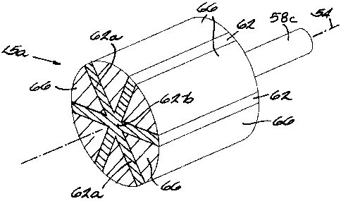
An electric motor 10 including a spoke permanent magnet rotor assembly 15
is schematically illustrated in FIG. 1. The specific motor
embodiment shown is for exemplary purposes. The invention described herein may
be used
in any type of electric motor having a spoke permanent magnet rotor.
As illustrated in FIG. 1, the motor 10 includes a motor housing 20 with first
and
second ends 24 and 28. The motor housing 20 may include a plurality of pieces
to
accommodate assembly and maintenance. Mounted within each of the first and
second ends
24 and 28 of the housing 20 is a respective bearing assembly 32. A stator 40
is mounted
CA 02485765 2004-10-22
-5-
within the housing 20. For simplicity, the stator end-windings are not
represented in FIG. 1.
The spoke permanent magnet rotor assembly 15 is rotationally supported within
the housing
20, such that the rotor assembly 50 may turn freely relative to the stator 40.
The rotor assembly 15 includes a spoke permanent magnet rotor 50 having an
axis of
rotation 54, and a shaft 58 to support the spoke permanent magnet rotor 50 for
rotation about
the axis of rotation 54. As discussed further below, the shaft 58 may include
a through-shaft,
a through-shaft assembly, stub shafts, stub shaft assemblies, and the like. A
first construction
of the spoke permanent magnet rotor assembly 15 is illustrated in FIGS. 2 and
3 as spoke
permanent magnet rotor assembly 15a. The rotor assembly 15a includes a spoke
permanent
magnet rotor 50a. A second construction of the spoke permanent magnet rotor
assembly 15
is illustrated in FIG. 4 as spoke permanent magnet rotor assembly 15b. The
rotor assembly
15b includes a spoke permanent magnet rotor 50b. A third construction of the
spoke
permanent magnet rotor assembly 15 is illustrated in FIG. 5 as spoke permanent
magnet rotor
assembly 15c. The rotor assembly 15c includes a spoke permanent magnet rotor
50c. A
fourth construction of the spoke permanent magnet rotor assembly 15 is
illustrated in FIG. 6
as spoke permanent magnet rotor assembly 15d. The rotor assembly 15d includes
a spoke
permanent magnet rotor 50d. A fifth construction of the spoke permanent magnet
rotor
assembly 15 is illustrated in FIG. 7 as spoke permanent magnet rotor assembly
15e. The
rotor assembly 15e includes a spoke permanent magnet rotor 50e. Like parts of
each
construction of the rotor assembly 15 are described and illustrated using like
reference
numerals.
Each spoke permanent magnet rotor 50 includes permanent magnet material 62 and
ferro-magnetic material 66. The permanent magnet material 62 extends outwardly
relative to
the axis of rotation 54 to form a plurality of angularly spaced, outwardly
extending spoke
portions of permanent magnet material 62a. In each of the illustrated
constructions, the
outwardly extending spoke portions of permanent magnet material 62a extend
radially
outward relative to the axis of rotation 54 to form a plurality of angularly
spaced, radially
extending spoke portions of permanent magnet material 62a. In other
constructions, the
outwardly extending spoke portions 62a may not extend radially outward
relative to the axis
of rotation 54. Further, in each of the illustrated constructions, the
radially extending spoke
portions of permanent magnet material 62a extend to the perimeter of the spoke
permanent
magnet rotor 50, and are therefore visible along the generally cylindrical
exterior surface of
the rotor 50. In other constructions, the radially extending spoke portions
62a may not extend
to the perimeter of the rotor 54.
CA 02485765 2004-10-22
-6-
For the spoke permanent magnet rotors 50a, 50b, 50c, and 50d, the permanent
magnet
material 62 also circumferentially surrounds the axis of rotation 58 (i.e.,
the permanent
magnet material 62 surrounds or encircles the entire axis of rotation 58 at
some radial
position) to form a circumferentially surrounding portion of permanent magnet
material 62b.
Each circumferentially surrounding portion of permanent magnet material 62b
extends from a
first radial position to a second radial position spaced from and outward of
the first radial
position. The distance between the first and second radial positions, and thus
the thickness of
the circumferentially surrounding portion of permanent magnet material 62b,
may vary.
For the spoke permanent magnet rotors 15a, 15b, and 15c, the first radial
position is
positioned substantially adjacent the axis of rotation 54, and the second
radial position is
positioned substantially adjacent the radially innermost portion of ferro-
magnetic material 66.
In constructions where the first radial position is positioned substantially
adjacent the axis of
rotation 54, the axis of rotation 54 often extends through the permanent
magnet material 62
(i.e., the permanent magnet material 62 extends along at least a portion of
the axis of rotation)
to form a center portion of permanent magnet material that is solid. The solid
center portion
of permanent magnet material includes the circumferentially surrounding
portion of
permanent magnet material 62b and the portion of permanent magnet material
through which
the axis of rotation 54 extends.
For the spoke permanent magnet rotor 15d and with respect to the rotor cross
section,
the first radial position is spaced radially from the axis of rotation 54, and
the second radial
position is positioned substantially adjacent the radially inner most portion
of ferro-magnetic
material 66. In constructions where the first radial position is spaced from
the axis of rotation
54, the first radial position is often positioned substantially adjacent the
radially outermost
portion of a center hole 70. The center hole 70 may be formed or machined in
the rotor 50.
Further, the center hole 70 may be of any shape and size.
The center hole 70 may accommodate a respective shaft 58 (e.g., a through-
shaft, a
through-shaft assembly). A center portion of permanent magnet material may
include the
circumferentially surrounding portion of permanent magnet material 62b that
surrounds the
shaft 58. The center hole 70 may remain open to form a hollow portion along
the axis of
rotation 54. In some embodiments, the axis of rotation 54 extends through the
hollow
portion. A center portion of permanent magnet material may include the
circumferentially
surrounding portion of permanent magnet material 62b and the hollow portion.
The center
hole 70 may be at least partially filled with either a non-magnetic material
and/or another
material to form a center core or core portion 74 (FIG. 6). A center portion
of permanent
_
CA 02485765 2012-11-13
67363-1348
- 7 -
magnet material may include the circumferentially surrounding portion of
permanent magnet
material 62b that surrounds the center core 74.
The ferro-magnetic material 66 forms pole pieces. Generally, a pole piece is
positioned between each set of circumferentially adjacent radially extending
portions of
permanent magnet material 62. The pole pieces collect and concentrate the
magnetic flux
generated by the magnetized permanent magnet material 62. In some
construction, the pole
pieces each include at least one interface surface that prevents movement
between the pole
piece and the adjacent permanent magnet material 62. Such construction
enhances rotor
structure integrity and mechanical strength. For example, the pole pieces of
the spoke
permanent magnet rotors 15b and 15c each include an interface surface.
With reference to FIG. 4, the interface surfaces of the pole pieces of the
spoke
permanent magnet rotor 15b each include a recess interface surface that forms
a recess 80
having a main portion 80a and a throat portion 80b. The throat portion 80b is
narrower than
the main portion 80a. The permanent magnet material 62 includes corresponding
interface
surfaces that engage the recess interface surfaces of the pole pieces.
With reference to FIG. 5, the interface surfaces of the pole pieces of the
spoke permanent
magnet rotor 15c each include a dovetail interface surface that forms a
dovetail 84 having a
main portion 84a and a throat portion 84b. The throat portion 84b is narrower
than the main
portion 84a. The permanent magnet material 62 includes corresponding interface
surfaces
that engage the dovetail interface surfaces of the pole pieces. The interface
surfaces of the
pole pieces and/or the permanent magnet material may be alternatively sized
and/or shaped in
other constructions.
In some constructions (e.g., the spoke permanent magnet rotors 50a, 50d, and
50e),
the rotor 50 may be formed from ferro-magnetic and permanent magnet powders
that are
compacted using a dynamic magnetic compaction process, or a similar type of
electromagnetic compaction process. The dynamic magnetic compaction process is
generally
explained in U.S. Patent Nos. 5,405,574; 5,611,139; 5,611,230; 5,689,797;
6,273,963;
6,432,554; and 6,524,526; and U.S. Patent Application Publication No.
2002/0192103 and
2003/0051614; each of which are assigned to IAP Research of Dayton, Ohio.
In one embodiment of the dynamic magnetic compaction
process, the ferro-magnetic and permanent magnet powers are loaded into an
electrically
conductive container (e.g., a container constructed of copper, steel, or
aluminum) for
simultaneous compaction. Specific reference is made to the above referenced
U.S. Patent
Application Publication No. 2002/0192103 which discloses a system and method
for loading
CA 02485765 2004-10-22
-8-
a plurality of powder materials in to an electromagnetic compaction press for
simultaneous
compaction. In other embodiments of the dynamic magnetic compaction process,
the ferro-
magnetic powder or the permanent magnet power is loaded into an electrically
conductive
container for individual compaction. For each embodiment, the loaded container
is placed at
the center of an electromagnetic coil. A current pulse is put through the
coil, creating high
magnetic pressure radially around the container. As the container collapses
around the
powder, the powder is compressed into a high density, near-net shape rotor 50
. Dies can also
be placed within the container to form rotor features around the dies (e.g., a
center hole,
interface surfaces, and the like).
Electromagnetic compaction can be done at a variety of temperatures (e.g.,
room
temperature, temperatures elevate above room temperature) and in a variety of
environments
(e.g., air, special atmospheres). After the rotor 50 is compacted, it can be
sintered to improve
its strength. For some applications, however, the rotors 50 are strong enough
that the
sintering step can be omitted.
In other constructions (e.g., the spoke permanent magnet rotors 50b and 50c),
the
rotor 50 may be formed of ferro-magnetic pole pieces and plastic bonded
permanent magnet
material injection molded around the pole pieces using an injection molding
process. The
ferro-magnetic pole pieces may be formed of ferro-magnetic laminations (e.g.,
interlocking
ferro-magnetic laminations, bonded together ferro-magnetic laminations, ferro-
magnetic
laminations secured using fasteners extending there through, and the like),
solid ferro-
magnetic material (e.g., solid steel), and/or composite ferro-magnetic
materials. The ferro-
magnetic pole pieces are placed in a fixture and the plastic bonded permanent
magnet
material (e.g., NdFeB, ferrite, and the like) is injection molded into the
voids left in the
fixture to produce a rotor 50. Utilization of pole pieces having interface
surfaces allows for
the creation of corresponding interface surfaces in the plastic bonded
permanent magnet
material during the injection molding process. Engagement between the
interface surfaces of
the pole pieces and the plastic bonded permanent magnet material increases the
structural
integrity of the rotor 50. In other embodiments, the plastic bonded permanent
magnet
material may be molded in a fixture to produce structure to which ferro-
magnetic pole pieces
are later added.
In other constructions, the rotor 50 may be formed of blocks of permanent
magnet
material and soft magnetic particles of ferro-magnetic material (e.g., iron
particles coated
with a non-magnetic binder such as a thermoplastic or resin so that the iron
particles are
space separated and bound together by the non-magnetic binder) molded around
the pieces of
CA 02485765 2012-11-13
67363-1348
- 9 -
permanent magnet material. In one embodiment, the pieces of permanent magnet
material
are placed in a fixture and the soft magnetic particles of ferro-magnetic
material is molded
into the voids of the fixture to produce a rotor 50. In other embodiments, the
soft magnetic
particles of ferro-magnetic material may be molded in a fixture to produce a
rotor core to
which pieces of permanent magnet material are later added. A molding process
that utilizes
soft magnetic particles of ferro-magnetic material is disclosed in U.S. Patent
No. 5,536,985,
which is assigned to General Motors Corporation of Detroit, Michigan.
In yet other constructions, the rotor 50 may be formed using other methods, or
a
The spoke permanent magnet rotor 50 may be attached to the shaft 58 during
and/or
In some construction, a magnetic or non-magnetic through-shaft extends through
the center
hole 70 of a respective rotor 50. To reduce or eliminate leakage magnetic flux
from the
magnetized permanent magnet material 62 toward a magnetic shaft, a sleeve of
non-magnetic
In other constructions, magnetic or non-magnetic stub shafts are connected
directly to
the rotor 50. The stub shafts may be connected using any suitable means (e.g.,
welding,
gluing, adhering, and the like). In yet other constructions, magnetic or non-
magnetic stub
shaft assemblies are connected directly to the rotor 50. The stub shaft
assemblies may be
30 connected using any suitable means (e.g., welding, gluing, adhering,
through-bolts, and the
like). In one construction, as illustrated in FIG. 2, a stub shaft assembly,
including a stub
shaft 58c and an end plate 58d, is connected to each end of the rotor 50. The
stub shafts 58c
are connected to the end plates 58d by a friction weld 58e, and the end plates
58d are
connected directly to each end of the rotor 50 by welds 58f. In other
constructions, the stub
CA 02485765 2012-11-13
,
67363-1348
- 10 -
shaft may be integrally connected to the end plate. Other types of stub shafts
and/or end
plates may be utilized to support the rotor 50 for rotation relative to the
stator in other
constructions. Generally, to minimize negative end-field effects during in-
situ magnetization
of the rotor assembly 15 and during motor operation, the end plates are formed
of a non-
magnetic and non-electrically conductive material. In some constructions, the
end plates may
be formed of a different material if the outside diameter of the end plate is
substantially
smaller in comparison to the outside diameter of the rotor 50 (FIG. 1). When
stub shafts and
stub shaft assemblies are utilized, the axis of rotation of the spoke
permanent magnet rotor 50
may extend through the permanent magnet material 62, or the spoke permanent
magnet rotor
50 may include a center hole 70 or a center core 74 filled with a magnetic or
non-magnetic
material. The rotor 50 may be magnetized using a conventional magnetizer and
fixture.
The embodiments described above and illustrated in the figures are presented
by way
of example only and are not intended as a limitation upon the concepts and
principles of the
present invention. As such, it will be appreciated by one having ordinary
skill in the art that
various changes in the elements and their configuration and arrangement are
possible without
departing from the scope of the present invention as set forth in the appended
claims.
,