Sélection de la langue

Search

Sommaire du brevet 2486162 

Énoncé de désistement de responsabilité concernant l'information provenant de tiers

Une partie des informations de ce site Web a été fournie par des sources externes. Le gouvernement du Canada n'assume aucune responsabilité concernant la précision, l'actualité ou la fiabilité des informations fournies par les sources externes. Les utilisateurs qui désirent employer cette information devraient consulter directement la source des informations. Le contenu fourni par les sources externes n'est pas assujetti aux exigences sur les langues officielles, la protection des renseignements personnels et l'accessibilité.

Disponibilité de l'Abrégé et des Revendications

L'apparition de différences dans le texte et l'image des Revendications et de l'Abrégé dépend du moment auquel le document est publié. Les textes des Revendications et de l'Abrégé sont affichés :

  • lorsque la demande peut être examinée par le public;
  • lorsque le brevet est émis (délivrance).
(12) Demande de brevet: (11) CA 2486162
(54) Titre français: CONSTRUCTION DE STRUCTURE
(54) Titre anglais: FRAMEWORK CONSTRUCTION
Statut: Réputée abandonnée et au-delà du délai pour le rétablissement - en attente de la réponse à l’avis de communication rejetée
Données bibliographiques
Abrégés

Abrégé français

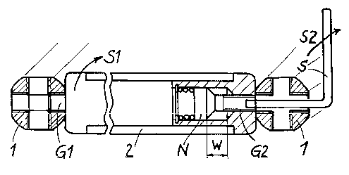
L'invention concerne une construction de structure, par exemple, d'un rayonnage de de livres ou équivalent, composée de plusieurs supports profilés (1, 2, 3) assemblés, notamment de deux types de supports profilés (1; 2, 3). Une première série de supports profilés (1), présentant des orifices filetés (g) perpendiculaires à leur axe longitudinal (B), sont à monter transversalement, c'est-à-dire dans le sens de la profondeur, tandis que la deuxième série de supports profilés (2, 3) qui sont dotés de boulons filetés (G1, G2) placés axialement à leurs extrémités, sont à monter dans le sens de la longueur et de la hauteur. Au moins un boulon fileté (G2) est mobile axialement et monté pivotant. Il présente à son extrémité libre un élément de prise, les boulons filetés (G2) étant serrés à fond, par exemple, à l'aide d'une clé à six pans (S) simple. Ainsi, la construction structure est constituée de seulement deux parties. Des éléments de fixation ou de liaison supplémentaires sont donc superflus. La construction de structure convient donc parfaitement à l'auto-assemblage.


Abrégé anglais


The invention relates to a framework construction, for example, a bookshelf or
the like, consisting of a plurality of profiled carriers (1, 2, 3), two types
of profiled carriers (1; 2, 3) being provided. The first profiled carriers
(1), which comprise tapped holes (g) arranged vertically in relation to the
longitudinal axis (B) thereof, are to be transversally mounted, i.e. depth-
wise, while the second profiled carriers (2, 3), which comprise axially
arranged threaded bolts (G1, G2) on the ends thereof, are to be mounted length-
wise and height-wise. At least one of the threaded bolts (G2) can be axially
displaced and rotatably mounted. Said threaded bolt comprises an engaging
device on its free end, which enables it (G2) to be screwed down, for example
by means of a simple spanner (S). In this way, the inventive framework
construction consists of only two parts. Additional connection or fixing
elements are not required. Said framework construction is very suitable for
self-assembly.

Revendications

Note : Les revendications sont présentées dans la langue officielle dans laquelle elles ont été soumises.


Claims
1. Framework construction comprising connectable and detachable profiled
members, characterised in that there are profiled beams (1) that comprise at
least
one tapped hole (g) that is arranged perpendicularly to their longitudinal
axis (B),
at least in the region of one of their two ends, wherein a respective
additional
profiled beam (2, 3) may be screwed into said tapped hole (g) using a threaded
bolt (G1, G2) arranged at the end of said profiled beam, coaxially or axially
to its
longitudinal axis.
2. Framework construction according to claim 1, characterised by at least two
types of profiled beams (1; 2, 3), namely first profiled beams (1), which
comprise,
at least in the region of one of their two ends, at least one tapped hole (g)
arranged
perpendicularly to their longitudinal axis (B), and second profiled beams (2,
3)
comprising threaded bolts (G1, G2) arranged at their end, coaxially or axially
to
their longitudinal axis.
3. Framework construction according to either claim 1 or claim 2,
characterised by at least one attachment that is arranged at one end of a
profiled
beam (1) and is connected thereto, and in which at least one tapped hole (g)
is
formed.
4. Framework construction according to either claim 2 or claim 3,
characterised in that the profiled been (1, 2) is configured as a hollow
profiled
member and an attachment in the form of a pin (Z1, Z2, Z3) is arranged in said
hollow profiled member.
5. Framework construction according to claim 4, characterised in that the pin
(Z1, Z2, Z3) is impressed in the hollow profiled member of the profiled beam
(1,
2).
7

6. Framework construction according to either claim 4 or claim 5,
characterised in that the pin (Z1, Z2, Z3) arranged in the hollow profiled
member
of the profiled beam (1, 2) is arranged in the hollow profiled member so
completely that it ends flush therewith.
7. Framework construction according to either claim 4 or claim 5,
characterised in that a part of the pin (Z1, Z2, Z3) arranged in the hollow
profiled
member of the profiled beam (1, 2) protrudes from the end of the hollow
profiled
member and is provided with a chamfer and a flange (C), for example, which has
the same diameter as the external diameter (d) of the profiled beam (1).
8. Framework construction according to either claim 6 or claim 7,
characterised in that the tapped hole (g) is introduced both through the
hollow
profiled member and in the pin (Z1) arranged therein.
9. Framework construction according to either claim 4 or claim 5,
characterised in that the tapped hole (g) is formed in the part of the pin
(Z1) that
protrudes from the end of the hollow profiled member of the profiled beam (1).
10. Framework construction according to either claim 1 or claim 2,
characterised in that there are profiled beams (2, 3) that comprise a threaded
bolt
(G2), which is axially displaceable and rotatable in the longitudinal axis (B)
of the
profiled beam (2, 3) or parallel to said longitudinal axis (B), at at least
one of their
two ends.
11. Framework construction according to claim 10, characterised in that the
profiled beams (2, 3) comprise a threaded bolt (G1), which is connected
fixedly
and non-rotatably to the profiled beam (2, 3), i.e. is neither displaceable
nor
rotatable axially, at their end opposite the end comprising the axially
displaceable
and rotatable threaded bolt (G2).
8

12. Framework construction according to either claim 10 or claim 11,
characterised in that the axially displaceable threaded bolt (G2) may be
pressed
into the profiled beam (2, 3), counter to the force of a spring (F), and the
threaded
bolt (G2) comprises an engaging device, such as an internal hexagon (1K), for
example, at its free end, in order to be able to rotate the threaded bolt (G2)
using
an implement, such as a hexagonal wrench (S), for example.
13. Framework construction according to claim 12, characterised in that the
tapped holes (g) that are provided for screwing-in the threaded bolt (G2) are
continuous, in order to be able to feed through an implement from the opposite
side of the profiled beam (1) comprising said tapped holes (g).
14. Framework construction according to any one of claims 1 to 13,
characterised in chat the profiled beams (1) comprise tapped holes (g),
preferably
four tapped holes (g), at their two ends, each of the tapped holes (g) of both
ends
of a profiled beam (1) being at the same angle to one another, in order to
allow
two further, corresponding profiled beams (2, 3), each screwed at one end, to
be
located parallel to each other.
15. Framework construction according to any one of claims 1 to 14,
characterised in that the profiled beams (1) comprises flat portions (D), each
located perpendicularly to the tapped holes (g), in order to provide the
respective
additional profiled beam (2, 3), which is screwed on here, with a secure and
stable
support.
16. Framework construction according to any one of claims 1 to 15,
characterised in that the profiled beams (1, 2, 3) comprise steel tubes that
are
round in cross-section.
9

17. Framework construction according to any one of claims 2 to 16,
characterised in that the first profiled beams (1), which comprise at least
one
tapped hole (g) arranged perpendicularly to their longitudinal axis (B), are
to be
incorporated transversely, i.e. in the depth (T), whereas the second profiled
beams
(2, 3), comprising threaded bolts (G1, G2) arranged coaxially or axially at
their
end, are to be incorporated in the length (L) and vertically (H).
10

Description

Note : Les descriptions sont présentées dans la langue officielle dans laquelle elles ont été soumises.


CA 02486162 2004-11-16
Framework construction
The present invention relates to a framework construction comprising
connectable
and detachable profiled beams.
s
It is known to connect profiled beams to a framework construction in a
detachable
manner, in order to manufacture household articles, such as items of furniture
and
room dividers. There is always a connecting element, in the form of a sphere
or a
cube, for example, at the centre of framework constructions of this type. The
~o connecting element is provided with a large number of holes or recesses, in
order
to screw in or clamp the profiled beams, which are generally configured as
round
tube. For this purpose, there are bolts or threaded bolts at the two ends of
the
profiled beams. Pins that act as expanding elements are also known. Owing to
the
modular structure of said framework constructions, the height, length and
shape of
t s the respective household article may be adapted in various ways and also
subsequently altered. Shelves, wall and ceiling elements, and also doors and
the
like may be Pitied or wedged into the frames formed by the framework
construction.
2o Since the known framework constructions, apart from profiled beams, also
always
comprise connecting elements, they are relatively complex and expensive. In
the
case of extended configurations comprising expanding pins, assembly may only
be undertaken by skilled personnel. During dismantling, which is usually
inevitable when moving house, the expanding pins are often damaged and have to
2s be replaced. It is known from EP 0 158 149 to connect the profiled beams to
the
spherical connecting element acting as the centre point using a threaded bolt.
The
threaded bolt protrudes axially from the front end of the profiled beams and
is to
be screwed into a tapped hole in a connecting element. A sleeve is provided
for
rotating the threaded bolt. Said sleeve is attached rotatably, but axially non-
3o displaceably, to the front end of the profiled beam. The threaded bolt is
screwed
into the spherical connecting element via an outer entrainment surface, which
is

CA 02486162 2004-11-16
configured with two sides or as a hexagon, by rotating the sleeve, and the
profiled
beam is thus secured to the connecting element. The drawbacks of said
construction are the high manufacturing costs of the inner entrainment
surfaces of
the sleeve for the threaded bolt and the high degree of complexity in the
production. It must be ensured that the axial play of the sleeve to the
profiled
beam is as low as possible, wherein it must still be possible to rotate the
sleeve
without exerting a high degree of force. However, axial play between the
sleeve
and the profiled beam is in practice inevitable. Moreover, as previously
stated, a
sphere that acts as a connecting element and is complex to produce is
necessary.
t o Since the sleeve, which is rotatable from outside, is provided with two
edges or a
hexagon, the sleeve, as a link from the round rod to the sphere, is also not
very
atti~active and makes the item of furniture much less pleasing to look at.
A framework construction in which a threaded bolt is axially displaceable in
the
~ s profiled beam, where it is secured against Calling out in a blind hole, by
means of
its head, is also known. The blind hole is formed by an annular end plate that
is
welded in the tube of the profiled beam. A complex, spherical connecting
element,
which acts as the centre point, is also provided in said framework
construction,
which increases the cost of the construction. A profiled beam may be assembled
20 on the spherical connecting element by screwing the threaded bolt using a
screwdriver that is to be fed through the connecting element. The threaded
bolt
may in this case cooperate with a spring, counter to the force of which it may
be
pressed into the end of the profiled beam. However, the assembly of the
additional
profiled beams is not always possible in this manner. Furthermore, said
25 framework construction has in practice proven not to be very stable. The
double
transition, from the first profiled beam to the sphere surface of the
connecting
element and therefrom to the following profiled beam; has an adverse effect.
On the basis of said discoveries, the object of the invention is to provide a
3o framework construction comprising connectable and detachable profiled beams
that may be produced easily and cost-effectively, may be assembled and
dismantled by a layman and is visually appealing.
2

CA 02486162 2004-11-16
The framework construction according to the invention corresponds to the
characterising features of claim 1. Further advantageous developments of the
inventive idea emerge from the dependent claims.
Preferred embodiments of the invention will be described below in greater
detail
with reference to the drawings, in which:
Fig. 1 + 2 show examples of cubic framework constructions;
to
Fig. 3 + 4 show construction details of a first proliled beam;
Fig. 5 - 8 show alternative examples of the first profiled beam;
Fig. 9 shows construction details of a second profiled beam;
Fig. 10 shows a section from a framework construction comprising three
profiled
beams screwed to one another.
zo The proposed framework construction comprises profiled beams, preferably in
the
form of a steel tube that is round in cross-section. The framework
construction is
substantially constructed on two different types of profiled beams. The first
type,
as is apparent from Fig. 1, form the profiled beams 1 to be incorporated
transversely. The length of said profiled beams 1 defines the depth T of the
zs framework construction - for example, a bookshelf, a sideboard, a case or
the like.
The second type of profiled beams form the profiled beams 2 to be incorporated
longitudinally and the profiled beams 3 to be incorporated vertically. The
length
and number of the profiled beams 2 to be incorporated longitudinally determine
the length L, and the length and number of the profiled beams 3 to be
incorporated
3o vertically determine the height H, of the framework construction.
3

CA 02486162 2004-11-16
As illustrated in Fig. 2, the structure of the framework construction does not
have
to be complete. Recesses, attachments and appendages may also be provided, in
flexible form. This is known as modular framework construction. In order to
simplify the drawings, all of the embodiments are illustrated in cube form,
i.e. the
profiled rods are at right angles to one another. However, the invention is
not
limited to said geometric form. As is also apparent from Fig. 2, it is also
possible
to use profiled beams of different lengths in a framework construction.
Fig. 3 to 8 show various examples of a profiled beam 1 to be incorporated
to transversely, i.e. in the depth T, in a cubic framework construction.
Tapped holes
g, which are preferably in a plane, are located at both ends of said profiled
beam
1. The axes of symmetry A of the tapped holes g extend perpendicularly to the
longitudinal axis B oC the profiled beam 1. Said tapped holes g may also be
formed in a different axial position of the profiled beam 1 and in a different
v ~ quantity, as required. The tapped holes g at one end of a profiled beam t
extend
through the longitudinal axis B of the profiled beam I at the same angle as
the
holes at the opposite end of the profiled beam 1.
Fig. 4 shows a section of the tapped holes g along the line a- a in Fig. 3. In
order
2o to attain a sufficiently supportive thread depth, in the case of thin-
walled tubes, it
is however advantageous, as illustrated in Fig. 5, to press an attachment, in
the
form of a pin Z1, hush into the profiled carrier 1. At the same time, said pin
Z1
forms a seal. Fig. 6 shows a visually more attractive seal, with a pin Z1
having a
bottom radius R or a chamfer and a flange C that exhibits the same diameter as
the
2s external diameter d of the cross-section of the profiled beam i. A further
expedient embodiment of the profiled carrier I, comprising four tapped holes
g, is
shown in Fig. 7 and 8. In this case, the tapped holes g are located in a pin
ZI,
which is rigidly connected to the profiled beam 1 by means of a press fit.
Said pin
Zl also comprises four flat portions D, which are each formed perpendicularly
to
3o the tapped holes g. Said flat portions serve the profiled beams 2 and 3 to
be
incorporated longitudinally and vertically, which profiled beams are screwed
into
the tapped holes g of the profiled beams 1 using threaded bolts G l and G2, in
4

CA 02486162 2004-11-16
order to provide secure and stable support. The two pins Z 1 of the one end
and the
other end of the first profiled beam 1 are pressed into the profiled beam 1
such
that the respective tapped holes g are at the same angle to one another, so
that
additional screwed-in profiled beams 2 and 3 extend parallel to each other at
said
two ends.
Fig. 9 shows the structural features of the profiled beams 2 and 3 to be
incorporated longitudinally and vertically. At one end of the profiled beam 2
and
3, a pin Z2 is pressed in. Said pin Z2 comprises a threaded bolt Gl, which is
o preferably configured in a single piece with the pin Z2 or is rigidly
connected to
the pin Z2. The threaded bolt G l is therefore rigidly connected to the
profiled
beam 2 or 3 to be incorporated longitudinally or vertically. At the opposite
end, a
pin Z3 is pressed tightly into the profiled beam 2 and 3. In said pin Z3, a
screw N
is axially displaceable counter to a spring F. In the illustrated
configuration, the
is screw N may be pressed into the profiled beam 2 or 3, counter to the force
K of
the spring F, by the distance w. The spring F is supported on the pressed-in
pin
Z3. On its shaft side, the screw N comprises an inner hexagon IK. It is freely
rotatable in the pin Z3, in both directions of rotation, using said inner
hexagon IK.
The two pins Z2 and Z3, which are rigidly connected to the profiled beams 2
and
20 3, may also be configured without a flange C. In this case, it is then
pressed in
Push with the outer surface of the profiled beam 2 or 3, as is apparent from
the
left-hand side of Fig. 9.
Fig. 10 shows a section cut out of a framework construction comprising two
25 profiled beams 1 to be incorporated transversely and one profiled beam 2 to
be
incorporated longitudinally. It is apparent here how the profiled beams 2 to
be
incorporated longitudinally and, similarly, the profiled beams 3 to be
incorporated
vertically are screwed to the profiled beams 1 to be incorporated
transversely,
using the protruding threaded bolts G1 and G2. In a first assembly step S1,
the
3o threaded bolt G1, which is rigidly connected to the profiled beam 2 and 3
to be
incorporated longitudinally or vertically, is screwed into the tapped hole g
of the
profiled beam 1 to be incorporated transversely, by rotating the corresponding
5

CA 02486162 2004-11-16
profiled beam 2 or 3. Said screwing-in may be done manually or using what is
known as a strap wrench. Said assembly is repeated until it is no longer
possible to
screw-in using the fixedly arranged threaded bolt G1. The assembly is then
continued in a second assembly step S2, in that the profiled beam 2 or 3 to be
s further assembled is placed against the first profiled beam I, by pressing
back the
moving threaded bolt G2 by the distance w, and is screwed using a hexagonal
wrench S, which is to be fed through the tapped holes g of the profiled beam
1.
This sequence of assembly siep S I and assembly step S2 is applied until the
desired framework construction has been produced. Dismantling takes place in
the
o reverse order.
Boih simple cubic and also geometrically complex framework constructions may
be constructed in this way and dismantled again using the reverse operating
procedure. No loose fastening elements, which might get lost or be delivered
~ 5 incomplete, are required Cor this purpose. A hexagonal wrench is the only
implement necessary. The framework construction according to the invention
manages entirely without centre or comer elements, such as spheres or cubes,
for
example.
0

Dessin représentatif
Une figure unique qui représente un dessin illustrant l'invention.
États administratifs

2024-08-01 : Dans le cadre de la transition vers les Brevets de nouvelle génération (BNG), la base de données sur les brevets canadiens (BDBC) contient désormais un Historique d'événement plus détaillé, qui reproduit le Journal des événements de notre nouvelle solution interne.

Veuillez noter que les événements débutant par « Inactive : » se réfèrent à des événements qui ne sont plus utilisés dans notre nouvelle solution interne.

Pour une meilleure compréhension de l'état de la demande ou brevet qui figure sur cette page, la rubrique Mise en garde , et les descriptions de Brevet , Historique d'événement , Taxes périodiques et Historique des paiements devraient être consultées.

Historique d'événement

Description Date
Inactive : Regroupement d'agents 2013-10-29
Demande non rétablie avant l'échéance 2009-05-14
Le délai pour l'annulation est expiré 2009-05-14
Inactive : Abandon.-RE+surtaxe impayées-Corr envoyée 2008-05-14
Réputée abandonnée - omission de répondre à un avis sur les taxes pour le maintien en état 2008-05-14
Lettre envoyée 2005-03-03
Inactive : Transfert individuel 2005-02-14
Inactive : Page couverture publiée 2005-01-31
Inactive : Lettre de courtoisie - Preuve 2005-01-27
Inactive : Notice - Entrée phase nat. - Pas de RE 2005-01-27
Demande reçue - PCT 2004-12-22
Exigences pour l'entrée dans la phase nationale - jugée conforme 2004-11-16
Demande publiée (accessible au public) 2003-12-04

Historique d'abandonnement

Date d'abandonnement Raison Date de rétablissement
2008-05-14

Taxes périodiques

Le dernier paiement a été reçu le 2007-05-09

Avis : Si le paiement en totalité n'a pas été reçu au plus tard à la date indiquée, une taxe supplémentaire peut être imposée, soit une des taxes suivantes :

  • taxe de rétablissement ;
  • taxe pour paiement en souffrance ; ou
  • taxe additionnelle pour le renversement d'une péremption réputée.

Les taxes sur les brevets sont ajustées au 1er janvier de chaque année. Les montants ci-dessus sont les montants actuels s'ils sont reçus au plus tard le 31 décembre de l'année en cours.
Veuillez vous référer à la page web des taxes sur les brevets de l'OPIC pour voir tous les montants actuels des taxes.

Historique des taxes

Type de taxes Anniversaire Échéance Date payée
Taxe nationale de base - petite 2004-11-16
Enregistrement d'un document 2005-02-14
TM (demande, 2e anniv.) - petite 02 2005-05-16 2005-05-05
TM (demande, 3e anniv.) - petite 03 2006-05-15 2006-04-06
TM (demande, 4e anniv.) - petite 04 2007-05-14 2007-05-09
Titulaires au dossier

Les titulaires actuels et antérieures au dossier sont affichés en ordre alphabétique.

Titulaires actuels au dossier
GENICON ANSTALT
Titulaires antérieures au dossier
LUKAS MATT
Les propriétaires antérieurs qui ne figurent pas dans la liste des « Propriétaires au dossier » apparaîtront dans d'autres documents au dossier.
Documents

Pour visionner les fichiers sélectionnés, entrer le code reCAPTCHA :


Pour visualiser une image, cliquer sur un lien dans la colonne description du document. Pour télécharger l'image (les images), cliquer l'une ou plusieurs cases à cocher dans la première colonne et ensuite cliquer sur le bouton "Télécharger sélection en format PDF (archive Zip)" ou le bouton "Télécharger sélection (en un fichier PDF fusionné)".

Liste des documents de brevet publiés et non publiés sur la BDBC .

Si vous avez des difficultés à accéder au contenu, veuillez communiquer avec le Centre de services à la clientèle au 1-866-997-1936, ou envoyer un courriel au Centre de service à la clientèle de l'OPIC.


Description du
Document 
Date
(aaaa-mm-jj) 
Nombre de pages   Taille de l'image (Ko) 
Description 2004-11-15 6 260
Revendications 2004-11-15 4 126
Dessin représentatif 2004-11-15 1 9
Dessins 2004-11-15 2 49
Abrégé 2004-11-15 2 92
Rappel de taxe de maintien due 2005-01-26 1 109
Avis d'entree dans la phase nationale 2005-01-26 1 191
Courtoisie - Certificat d'enregistrement (document(s) connexe(s)) 2005-03-02 1 105
Rappel - requête d'examen 2008-01-14 1 118
Courtoisie - Lettre d'abandon (taxe de maintien en état) 2008-07-08 1 173
Courtoisie - Lettre d'abandon (requête d'examen) 2008-09-02 1 165
PCT 2004-11-15 4 99
Correspondance 2005-01-26 1 25
Taxes 2005-05-04 1 61
Taxes 2006-04-05 1 43
Taxes 2007-05-08 1 51